| |
| This section is definitely under
construction. |
| |
 E
All I have done is spent an hour thinking about how I want my schematic to
look. I haven't vetted this with anyone yet but as soon as I do,
I'll post it for your viewing pleasure. Comments and thoughts are
welcome. (7/15/05) E
All I have done is spent an hour thinking about how I want my schematic to
look. I haven't vetted this with anyone yet but as soon as I do,
I'll post it for your viewing pleasure. Comments and thoughts are
welcome. (7/15/05) |
| |
  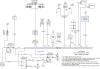 F
The electrical system is set as good as it's going to be. Now is
time to start pulling wires. Some
things are still unknown, like the wire sizes required for the Emag/Pmag's.
Once I buy those things, I will adjust the size accordingly and update the
drawings. This is version 3.5, a lot of time went into this and I
highly recommend all builders take some time to work out there electrical
system before pulling wires. Especially first time builders like
myself. (1/8/06) F
The electrical system is set as good as it's going to be. Now is
time to start pulling wires. Some
things are still unknown, like the wire sizes required for the Emag/Pmag's.
Once I buy those things, I will adjust the size accordingly and update the
drawings. This is version 3.5, a lot of time went into this and I
highly recommend all builders take some time to work out there electrical
system before pulling wires. Especially first time builders like
myself. (1/8/06) |
| |
|
   E
The amount of time I have put into designing the electrical system has
blown me away. At this point I have 18 hours logged on designing it
and I'm sure the actual amount of time is two or three times that.
These three pictures are final, I HOPE! I've ordered the switches
breakers and pull type circuit breakers from
Affordable Panels as they seem to have very competitive prices and I
really like their customer service. I've elected to go with
duel Pmag's over one Emag and one Pmag which settled the switch and wire
size issue. When designing your electrical system I highly recommend
buying the
Bob Knuckolls' AeroElectric book. It covers everything you will
need to know about homebuilt electrical systems and more. (2/11/06) E
The amount of time I have put into designing the electrical system has
blown me away. At this point I have 18 hours logged on designing it
and I'm sure the actual amount of time is two or three times that.
These three pictures are final, I HOPE! I've ordered the switches
breakers and pull type circuit breakers from
Affordable Panels as they seem to have very competitive prices and I
really like their customer service. I've elected to go with
duel Pmag's over one Emag and one Pmag which settled the switch and wire
size issue. When designing your electrical system I highly recommend
buying the
Bob Knuckolls' AeroElectric book. It covers everything you will
need to know about homebuilt electrical systems and more. (2/11/06) |
| |
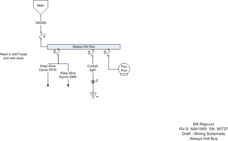
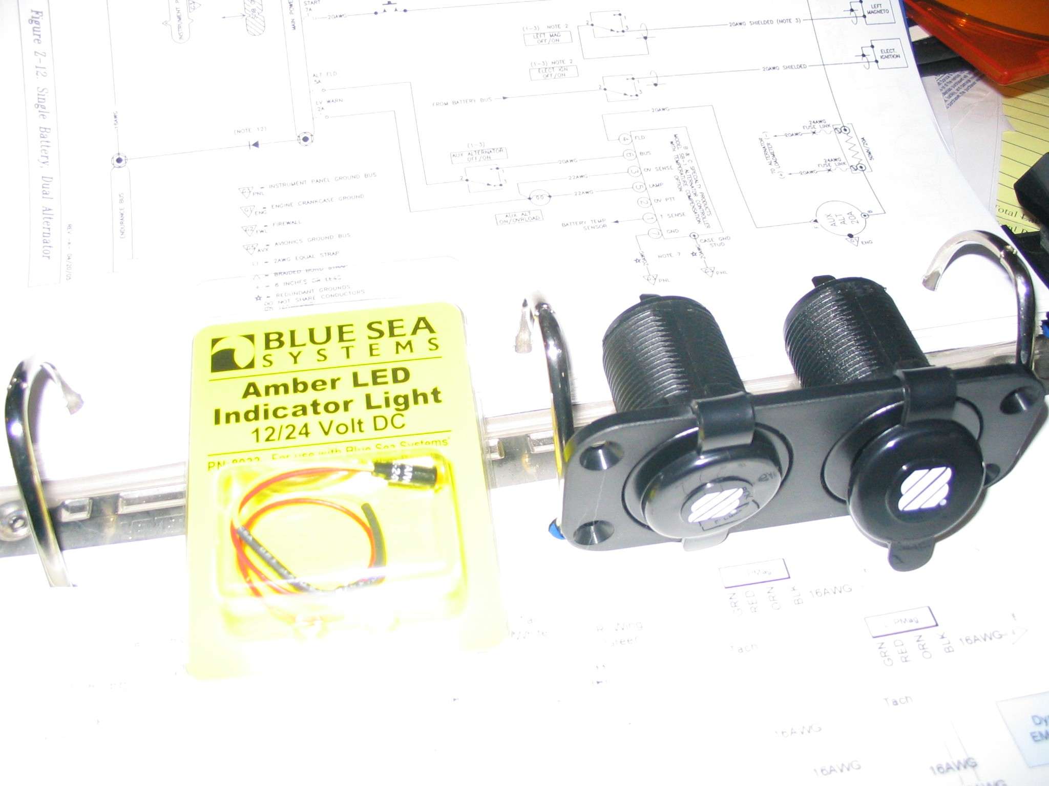
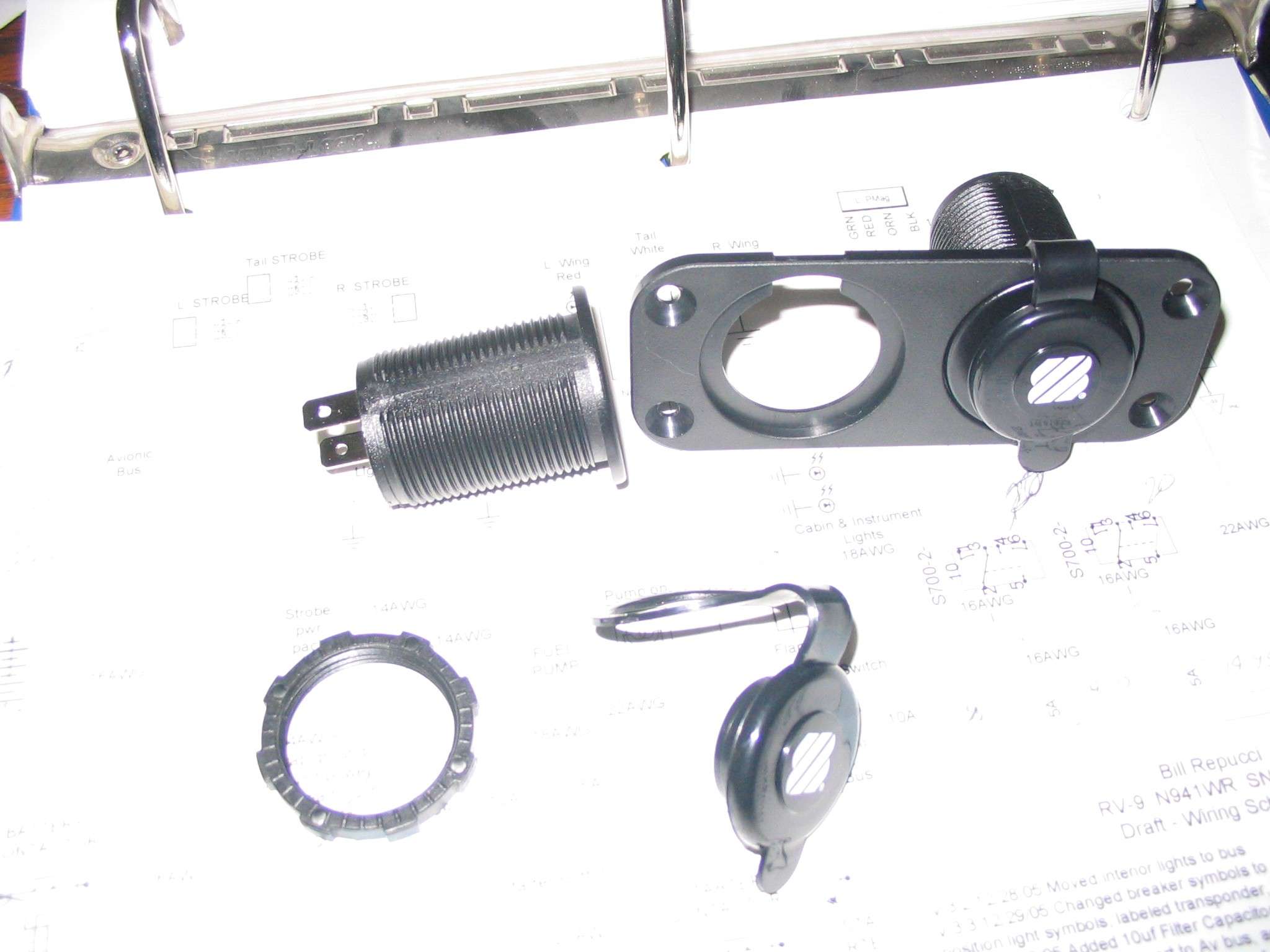
  F
Part of my electrical system will include two power ports AKA cigarette
lighter plugs. These are pictures of the duel plug unit I found at
West Marine. I like that they come with a face plate, plug covers,
and give you the option of mounting them in their own hole. One plug
will be switched with the avionics master and the other will be on the
"Always Hot" bus so I can use a trickle charger or plug a computer, cell
phone, or whatever into it without turning on the master. This
always hot plug will get a bit heavier wiring and circuit breaker to
handle that trickle charger. The little amber LED light in the right
picture will be used as a "Fuel Pump On" light and will be mounted high in
the panel so I can see it in my pre-takeoff scan and as a reminder should
I leave the fuel pump on after take off. Here is a picture of the
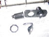
plugs fitted in the instrument panel. (2/11/06) F
Part of my electrical system will include two power ports AKA cigarette
lighter plugs. These are pictures of the duel plug unit I found at
West Marine. I like that they come with a face plate, plug covers,
and give you the option of mounting them in their own hole. One plug
will be switched with the avionics master and the other will be on the
"Always Hot" bus so I can use a trickle charger or plug a computer, cell
phone, or whatever into it without turning on the master. This
always hot plug will get a bit heavier wiring and circuit breaker to
handle that trickle charger. The little amber LED light in the right
picture will be used as a "Fuel Pump On" light and will be mounted high in
the panel so I can see it in my pre-takeoff scan and as a reminder should
I leave the fuel pump on after take off. Here is a picture of the
plugs fitted in the instrument panel. (2/11/06) |
| |
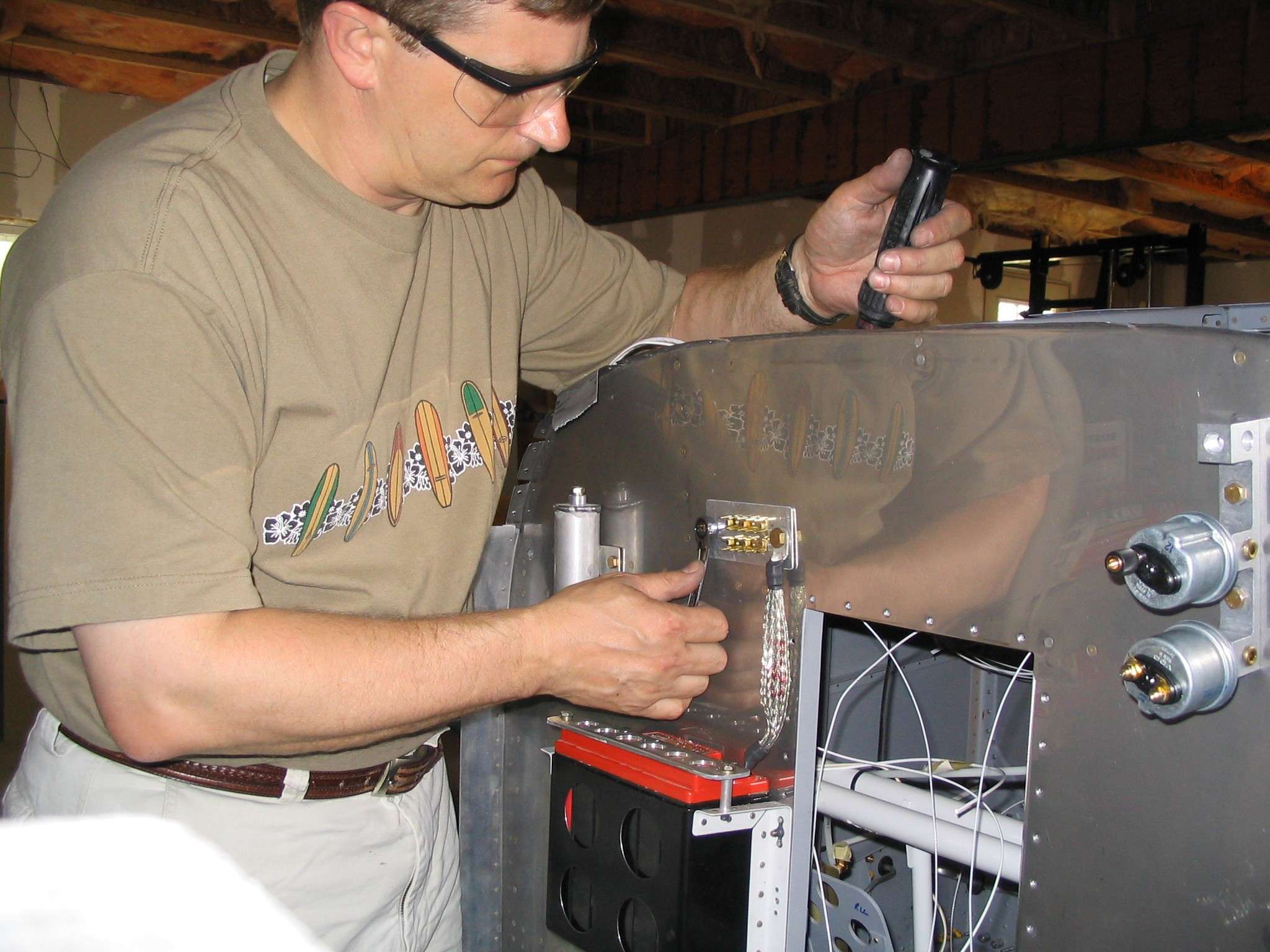
  E
Yes, that is wires you see. Both power ports are now wired as is the
power lead for the position lights and fuel pump. A common ground
block is on order and once that is installed these wires will be
terminated at the firewall. Keeping the schematic close by at this
stage is very handy. As each wire is run and labeled the
corresponding circuit is checked off. (4/11/06) E
Yes, that is wires you see. Both power ports are now wired as is the
power lead for the position lights and fuel pump. A common ground
block is on order and once that is installed these wires will be
terminated at the firewall. Keeping the schematic close by at this
stage is very handy. As each wire is run and labeled the
corresponding circuit is checked off. (4/11/06) |
| |
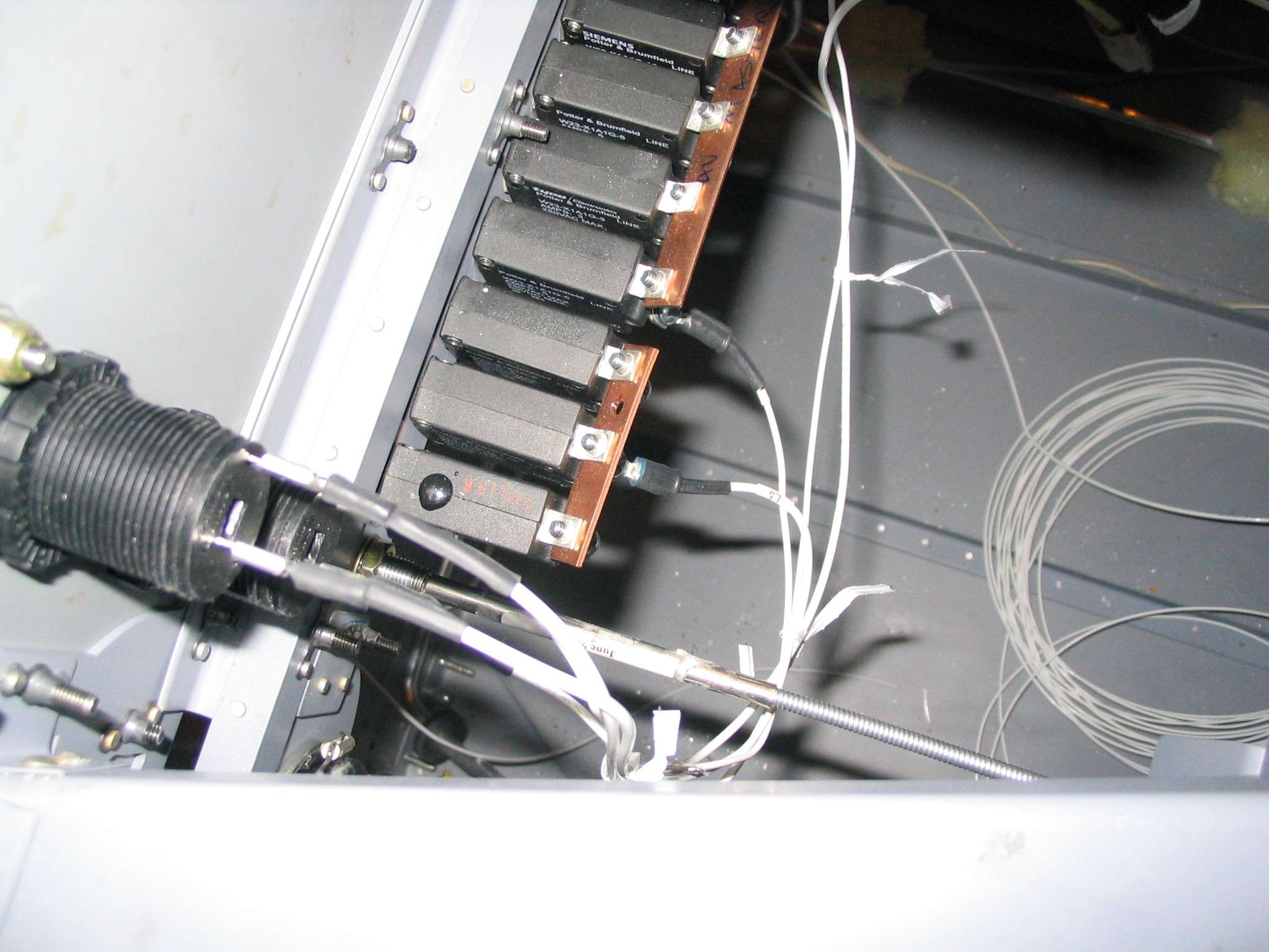
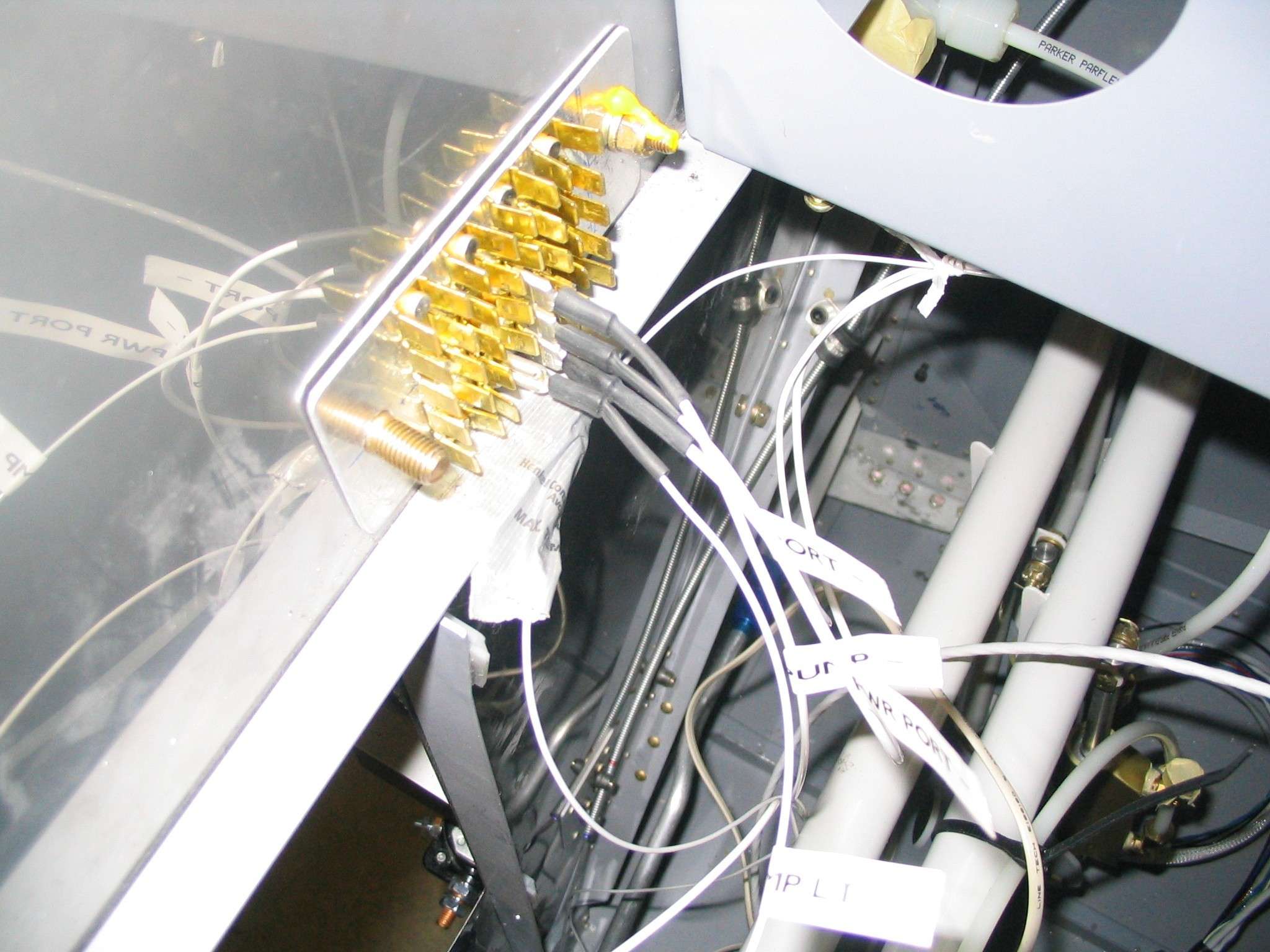
   F
Spent the day making the ground blocks, terminating some ground wires,
wiring up the flap motor, and thinking about the project. There are
20 tab connectors on the firewall side and 50 on the cabin side. The ground
blocks will be connected via a brass bolt. For now
an AN-5 bolt will hold things together until I procure a brass replacement. It sure felt good to
start terminating things on the ground block rather than just labeling
them and draping them over the firewall. Not to mention watching the
flaps motor up and down on command from the flap switch! (4/16/06) F
Spent the day making the ground blocks, terminating some ground wires,
wiring up the flap motor, and thinking about the project. There are
20 tab connectors on the firewall side and 50 on the cabin side. The ground
blocks will be connected via a brass bolt. For now
an AN-5 bolt will hold things together until I procure a brass replacement. It sure felt good to
start terminating things on the ground block rather than just labeling
them and draping them over the firewall. Not to mention watching the
flaps motor up and down on command from the flap switch! (4/16/06) |
| |
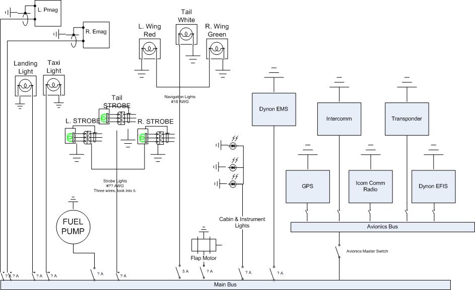
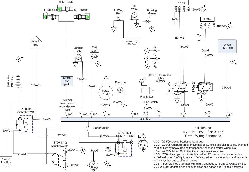
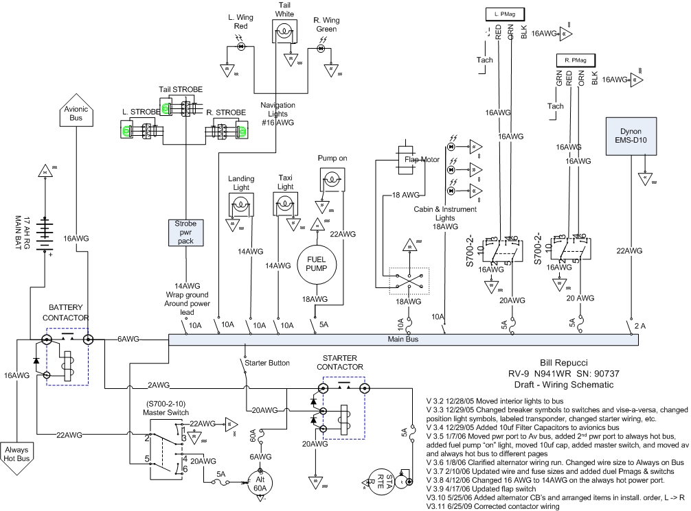
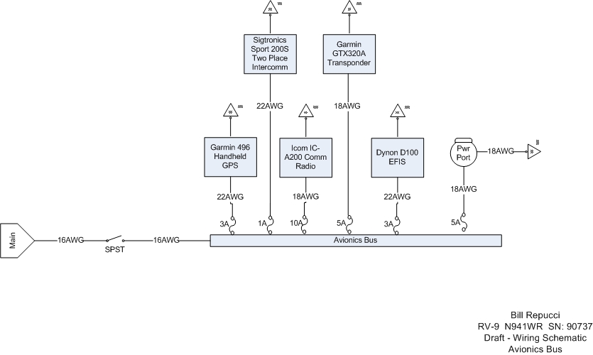
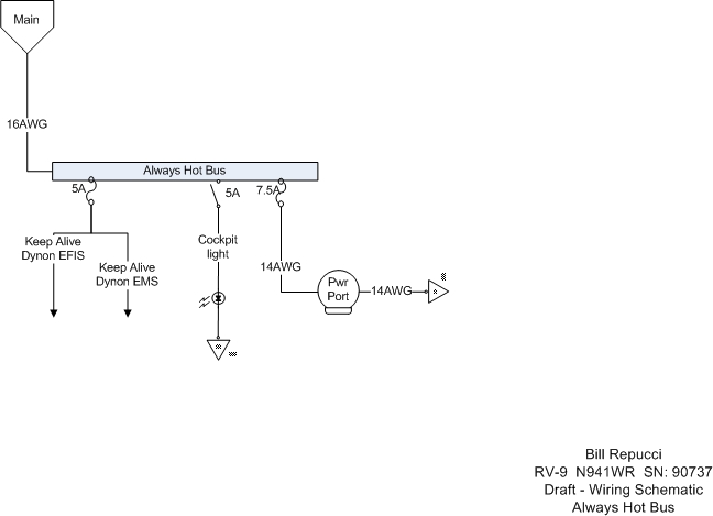
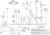
|
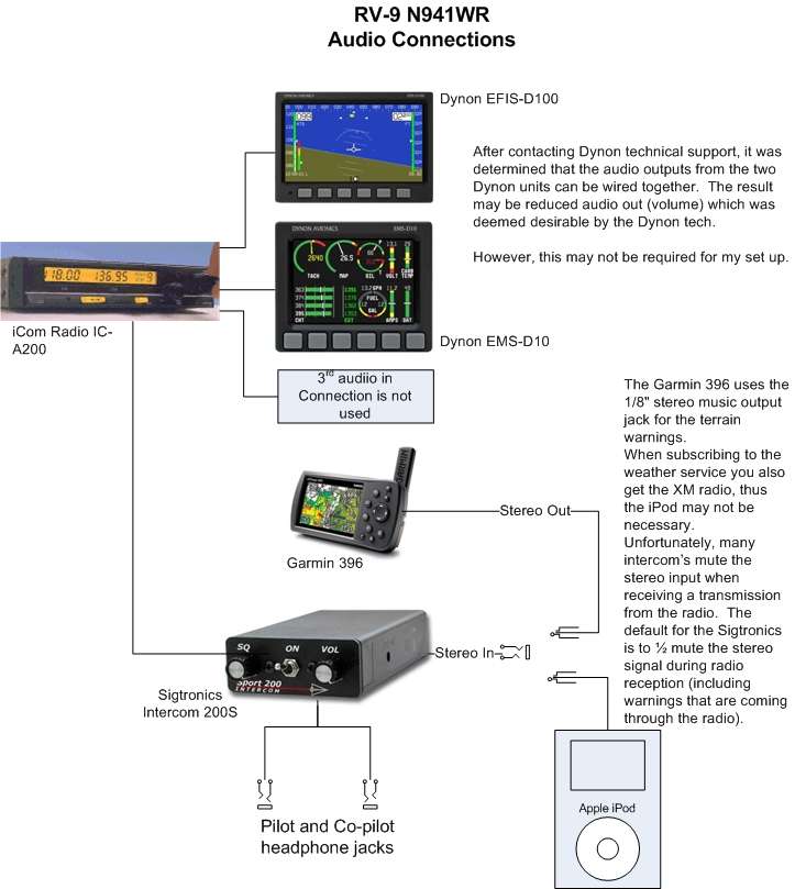
   E
Like I actually thought I was finished updating these drawings in
February!? As I run wires I am making small changes, up sizing wire
sizes because I don't have any 16 AWG for instance, adding the flap switch
diagram, etc. I'll just use this paragraph to post my updated wiring
diagram. (4/16/06) Note - The drawings were updated once
again and I'm sure there are still inaccuracies in these drawings.
If you spot one, please let me know. (5/18/08). E
Like I actually thought I was finished updating these drawings in
February!? As I run wires I am making small changes, up sizing wire
sizes because I don't have any 16 AWG for instance, adding the flap switch
diagram, etc. I'll just use this paragraph to post my updated wiring
diagram. (4/16/06) Note - The drawings were updated once
again and I'm sure there are still inaccuracies in these drawings.
If you spot one, please let me know. (5/18/08). |
| |
|
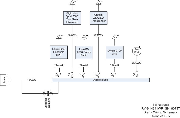
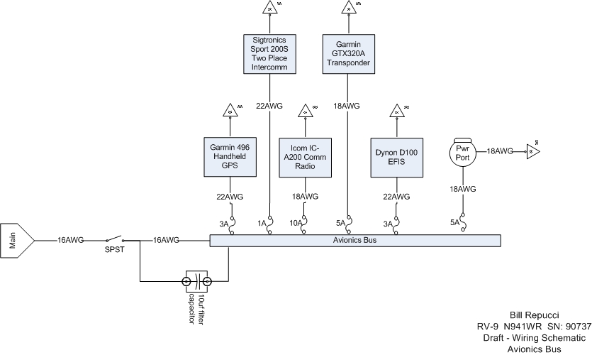
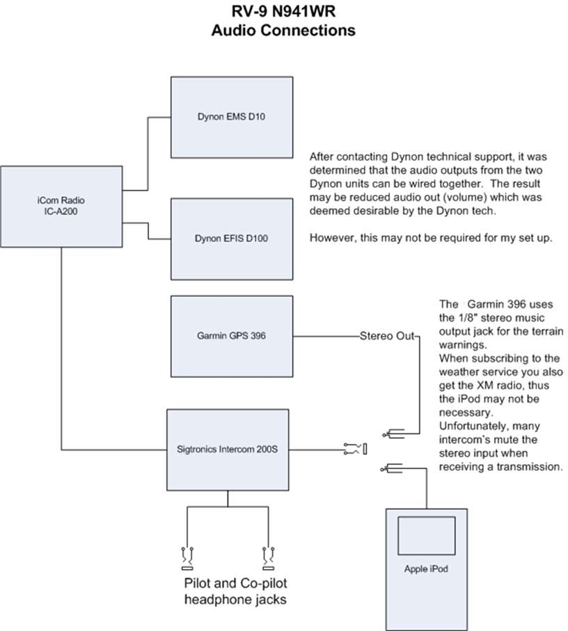
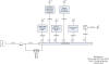
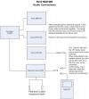 F
Now it is time to start connecting the audio components of my panel.
A Sigtronics 200S stereo intercom will be the heart of the system.
An Apple iPod will be plugged into its stereo input jack. The GPS
outputs it terrain warnings through the 1/8" stereo output plug.
This means either the iPod or XM radio, not both. The
iCom
IC-A200 radio will be connected directly to the intercom, leaving three
items that need to be connected; the
Dynon EFIS D100,
Dyon EMS D10, and
Garmin GPS 396. The iCom radio has two audio input "ports" which can
be connected to two of these items so they can be played (heard?) through
the intercom. After posting a question regarding the
Dynon Smart Avionics Bus (DSAB) interconnectivity on the
Dynon Forum I found that the two units do not share audio output
function and that both units must be connect to the audio system.
However, Dynon did add that the audio out's from the two units could be
connected together. With the understanding that the 396 will "play"
through the stereo input, the two Dynon units will have their own input
channels on the radio. F
Now it is time to start connecting the audio components of my panel.
A Sigtronics 200S stereo intercom will be the heart of the system.
An Apple iPod will be plugged into its stereo input jack. The GPS
outputs it terrain warnings through the 1/8" stereo output plug.
This means either the iPod or XM radio, not both. The
iCom
IC-A200 radio will be connected directly to the intercom, leaving three
items that need to be connected; the
Dynon EFIS D100,
Dyon EMS D10, and
Garmin GPS 396. The iCom radio has two audio input "ports" which can
be connected to two of these items so they can be played (heard?) through
the intercom. After posting a question regarding the
Dynon Smart Avionics Bus (DSAB) interconnectivity on the
Dynon Forum I found that the two units do not share audio output
function and that both units must be connect to the audio system.
However, Dynon did add that the audio out's from the two units could be
connected together. With the understanding that the 396 will "play"
through the stereo input, the two Dynon units will have their own input
channels on the radio.
What is all this stuff trying to tell me? The EFIS will give audio
stall warning from the AoA port. The EMS will announce any out of
bounds condition regarding engine operation such as high or low oil
pressure, temperature, etc. The GPS can output terrain warnings and
XM radio signal. (4/18/06) |
| |
|
 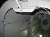 E
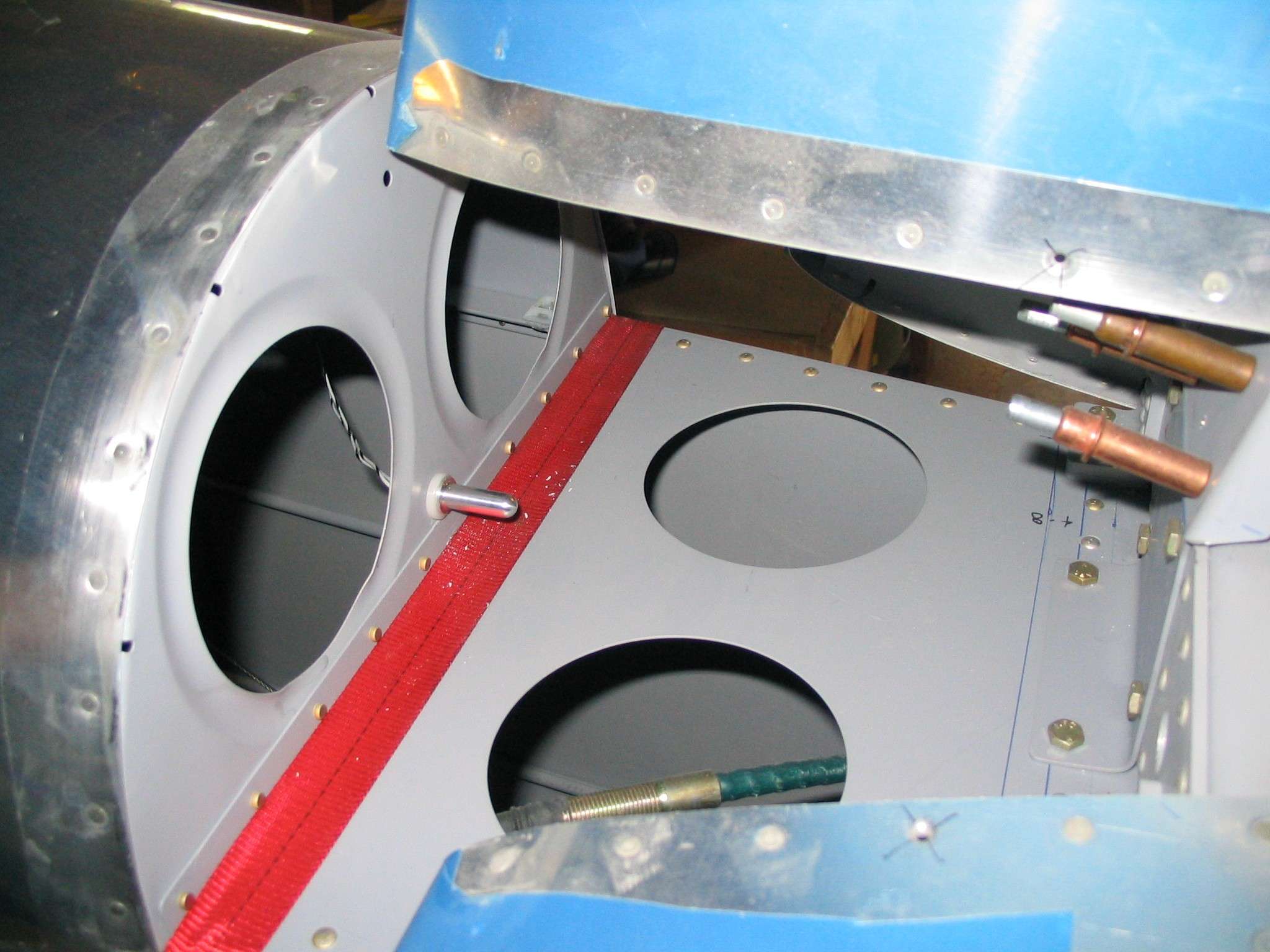
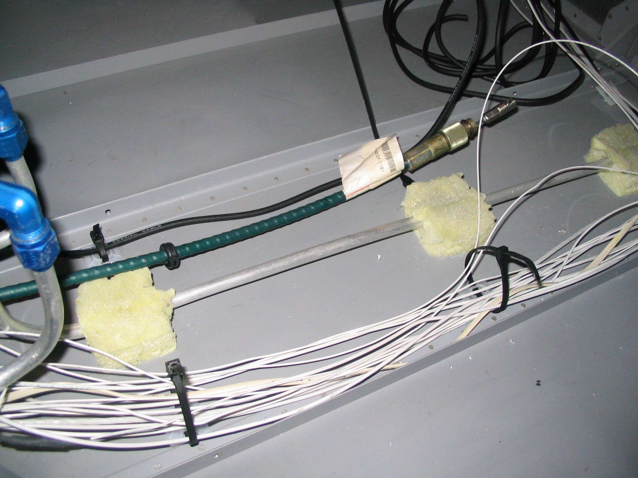
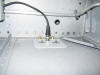
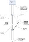
These pictures could go almost anywhere. What you are looking at is
the Outside Air Temperature (OAT) probe and its associated wire runs.
The OAT for the Dynon units connect at the remote compass. Thus, the
compass is required if you want to use the OAT. The only use for the
OAT is so the system can calculate True Airspeed. This location will
be covered by some fiberglass fairing. Even though it might heat up
with the aircraft on the ground, once it starts moving the tail section
will get fresh air and by the time I hit cruising altitudes I suspect it
will register correctly. This location was chosen in an effort to
protect the probe. Remember, this will be a tail dragger and there
is a chance it would get damage if placed under the HS. The tray
that will hold the remote compass is visible at the top of the second
picture. (The red strap is to keep my fuselage from tipping forward
when I climb in the cockpit.) (4/19/06) E
These pictures could go almost anywhere. What you are looking at is
the Outside Air Temperature (OAT) probe and its associated wire runs.
The OAT for the Dynon units connect at the remote compass. Thus, the
compass is required if you want to use the OAT. The only use for the
OAT is so the system can calculate True Airspeed. This location will
be covered by some fiberglass fairing. Even though it might heat up
with the aircraft on the ground, once it starts moving the tail section
will get fresh air and by the time I hit cruising altitudes I suspect it
will register correctly. This location was chosen in an effort to
protect the probe. Remember, this will be a tail dragger and there
is a chance it would get damage if placed under the HS. The tray
that will hold the remote compass is visible at the top of the second
picture. (The red strap is to keep my fuselage from tipping forward
when I climb in the cockpit.) (4/19/06) |
| |
|
 F
After much questioning, searching and head scratching I discovered the
iCom radio has three mono inputs and the Garmin GPS outputs its terrain
warnings out through it 1/8" stereo jack. Thus the new design.
The only downside of this configuration is that the intercom 1/2 mutes the
stereo input when something is coming in over the radio. One thing
to keep in mind is that even though the radio and the signals going
through the radio are mono, they will be played in both left and right
channels. Also, modern intercom designs, such as the Sigtronics pass
through any radio signal when turned off or in failure mode. What
you wont be able to hear is the passenger. For a Day/Night VFR ship,
I do not consider this a safety issue. (5/1/06) F
After much questioning, searching and head scratching I discovered the
iCom radio has three mono inputs and the Garmin GPS outputs its terrain
warnings out through it 1/8" stereo jack. Thus the new design.
The only downside of this configuration is that the intercom 1/2 mutes the
stereo input when something is coming in over the radio. One thing
to keep in mind is that even though the radio and the signals going
through the radio are mono, they will be played in both left and right
channels. Also, modern intercom designs, such as the Sigtronics pass
through any radio signal when turned off or in failure mode. What
you wont be able to hear is the passenger. For a Day/Night VFR ship,
I do not consider this a safety issue. (5/1/06) |
| |
|
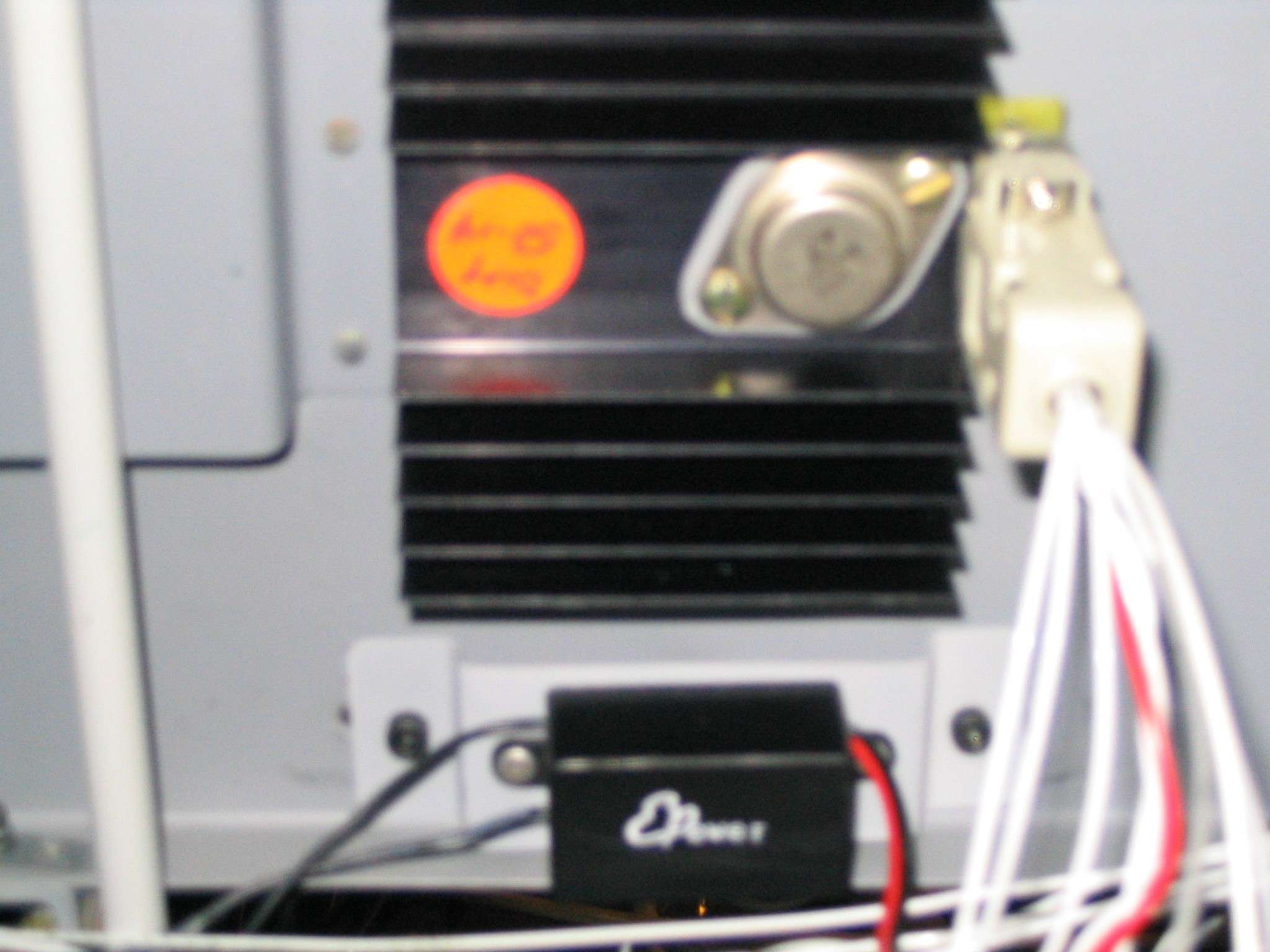
 E
The wiring is so much fun! I have elected to use plate nuts wherever
possible to hold stuff. Here is a picture of the dimmer controller
over the transformer / converter for the
electroluminescent strips above the switch panels. They are held in
place with plate nuts and 8-32 cap screws. The cap screws are easier
to use, IMHO, and are much easier to install and remove than standard
Phillips head screws. These are mounted on the forward side of the
sub-panel. (8/23/06) E
The wiring is so much fun! I have elected to use plate nuts wherever
possible to hold stuff. Here is a picture of the dimmer controller
over the transformer / converter for the
electroluminescent strips above the switch panels. They are held in
place with plate nuts and 8-32 cap screws. The cap screws are easier
to use, IMHO, and are much easier to install and remove than standard
Phillips head screws. These are mounted on the forward side of the
sub-panel. (8/23/06) |
| |
|
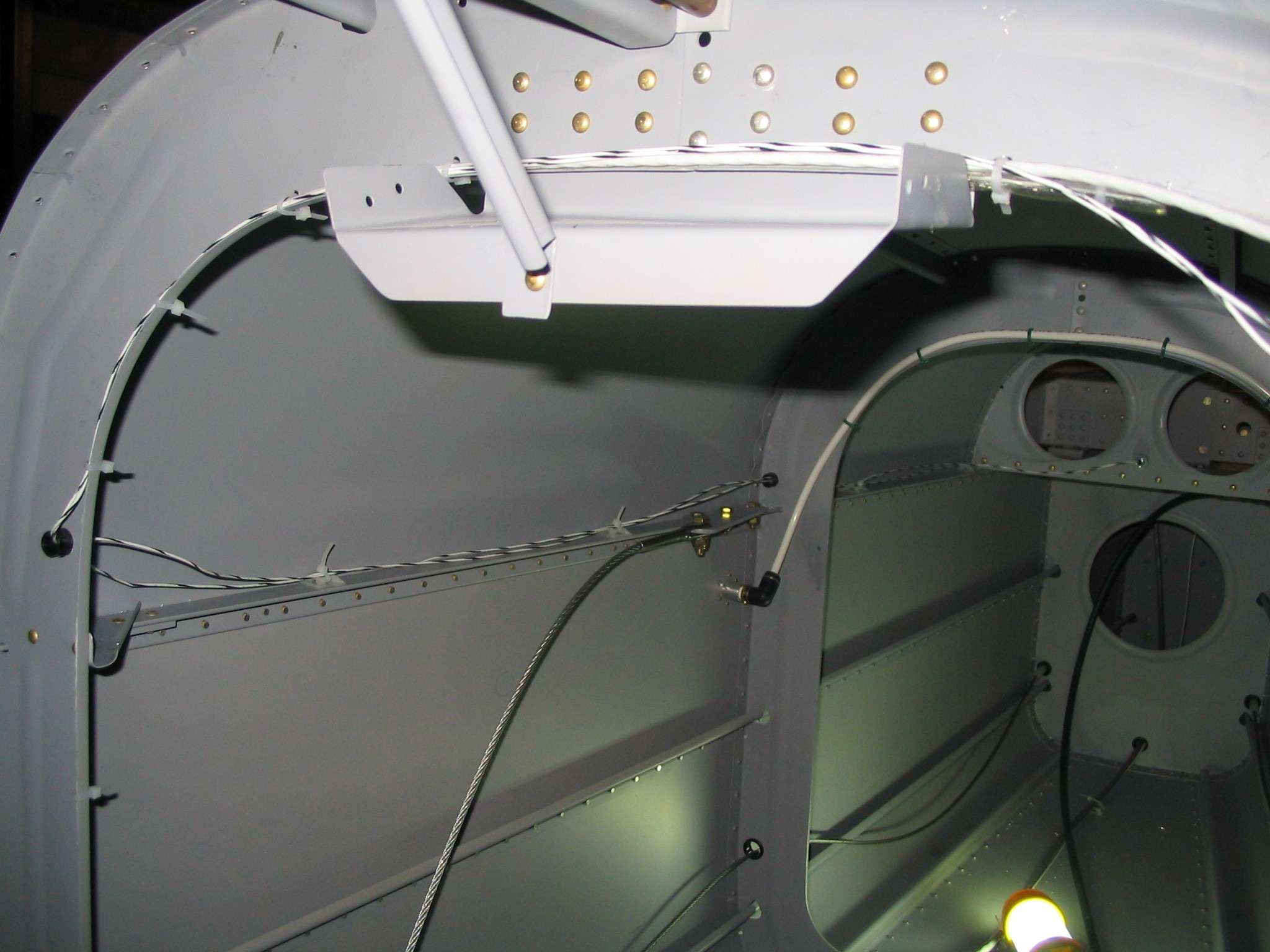
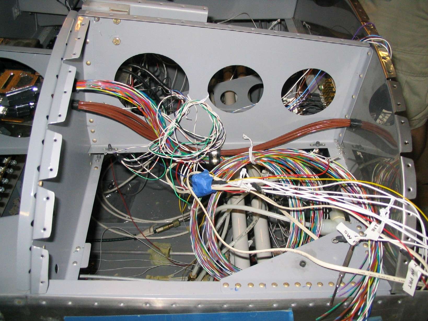
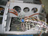
 F
Figuring out how and where to run wires is always a challenge
for every builder. This is a shot of the forward floor. Notice
how all the electrical and ground wires are running up the right side of
the fuel line and the radio antenna cable is running up the left side.
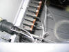
This, I hope, will help reduce noise in my transmissions. (8/23/06) F
Figuring out how and where to run wires is always a challenge
for every builder. This is a shot of the forward floor. Notice
how all the electrical and ground wires are running up the right side of
the fuel line and the radio antenna cable is running up the left side.
This, I hope, will help reduce noise in my transmissions. (8/23/06)
|
| |
|
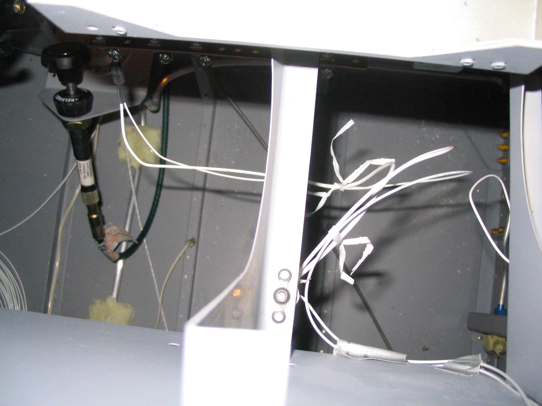
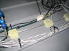
  E
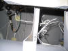
These are just
some pictures of my wire mess. It is coming together and will be
straightened out before I close up the top skin. I was using twist
ties to hold the wires in the correct place and help keep it neat.
Using Adel clamps on the bottom of the ribs has been a great help.
If I run out of room in a clamp, it gets replaced with a larger one.
It can't get much simpler than that. (8/23/06) E
These are just
some pictures of my wire mess. It is coming together and will be
straightened out before I close up the top skin. I was using twist
ties to hold the wires in the correct place and help keep it neat.
Using Adel clamps on the bottom of the ribs has been a great help.
If I run out of room in a clamp, it gets replaced with a larger one.
It can't get much simpler than that. (8/23/06) |
| |
|
 F
These are so
many options when it comes time to install the antennas. The
transponder antenna is located right behind the firewall on the right
side, next to the fuel vent. The com antenna is forward of the spar,
under the pilots left knee with the aft two #8 screws piercing the spar
flange. In retrospect, it might have been better to have put the com
antenna behind the firewall and the transponder antenna just in front of
the spar. One advantage of keeping everything forward of the spar is
that none of those thick cables have to go through the spar, which has
limited passages. The remaining hole, seen in this picture will be
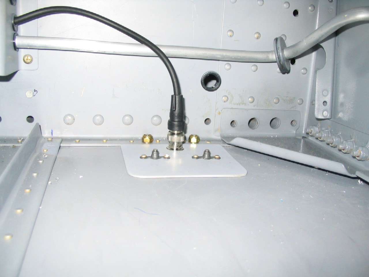
used as the pass through for the pitot and AoA lines. F
These are so
many options when it comes time to install the antennas. The
transponder antenna is located right behind the firewall on the right
side, next to the fuel vent. The com antenna is forward of the spar,
under the pilots left knee with the aft two #8 screws piercing the spar
flange. In retrospect, it might have been better to have put the com
antenna behind the firewall and the transponder antenna just in front of
the spar. One advantage of keeping everything forward of the spar is
that none of those thick cables have to go through the spar, which has
limited passages. The remaining hole, seen in this picture will be
used as the pass through for the pitot and AoA lines.
Big news, right
after dinner I dragged Nora into the basement so we could try out the
electronics. As expected, the radio could transmit and receive, the
intercom worked, and so did the audio in jack for the stereo intercom.
The only thing left to test is the warning tones from the two Dynon units.
(9/1/06) |
| |
|
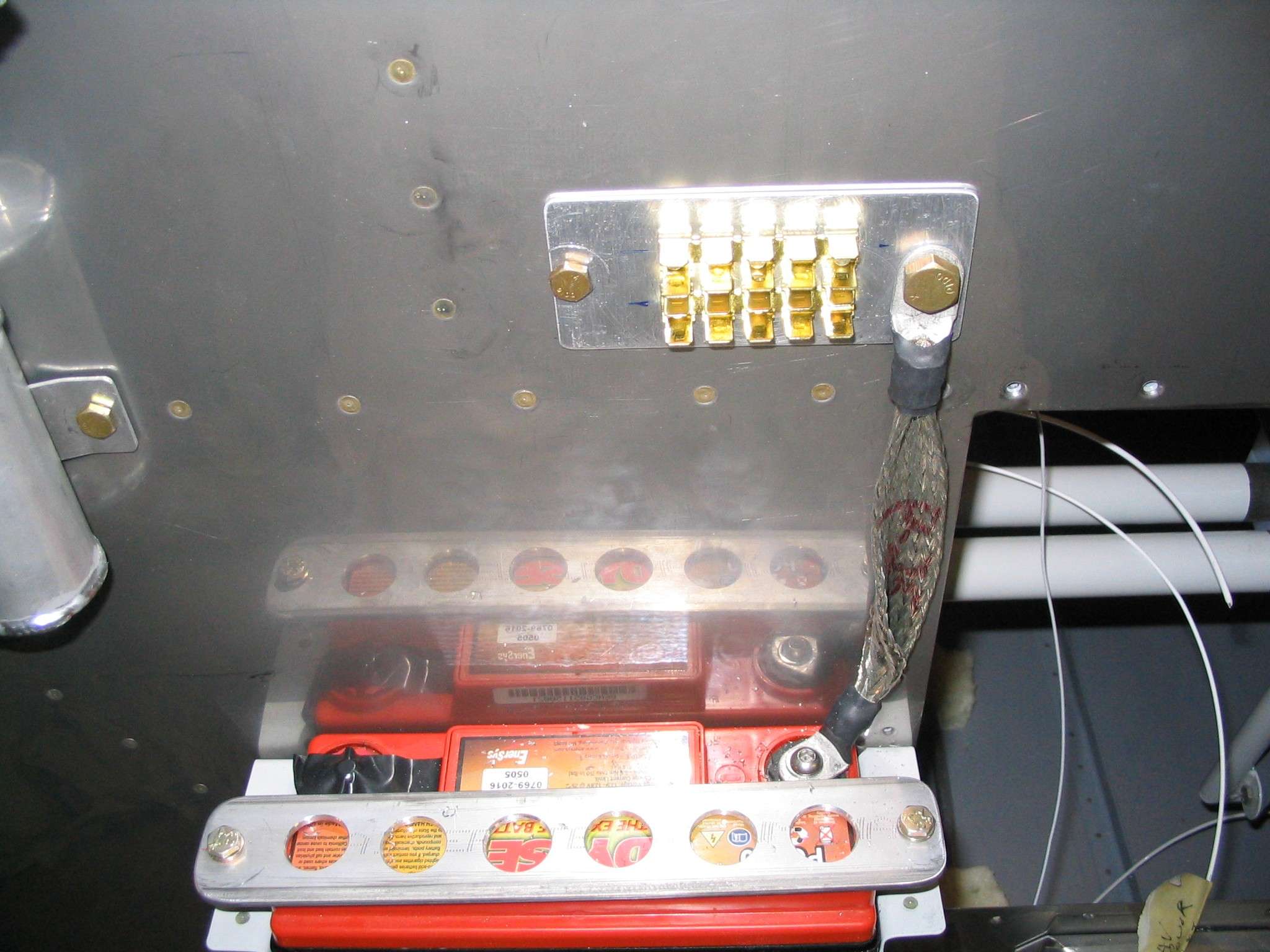
 E
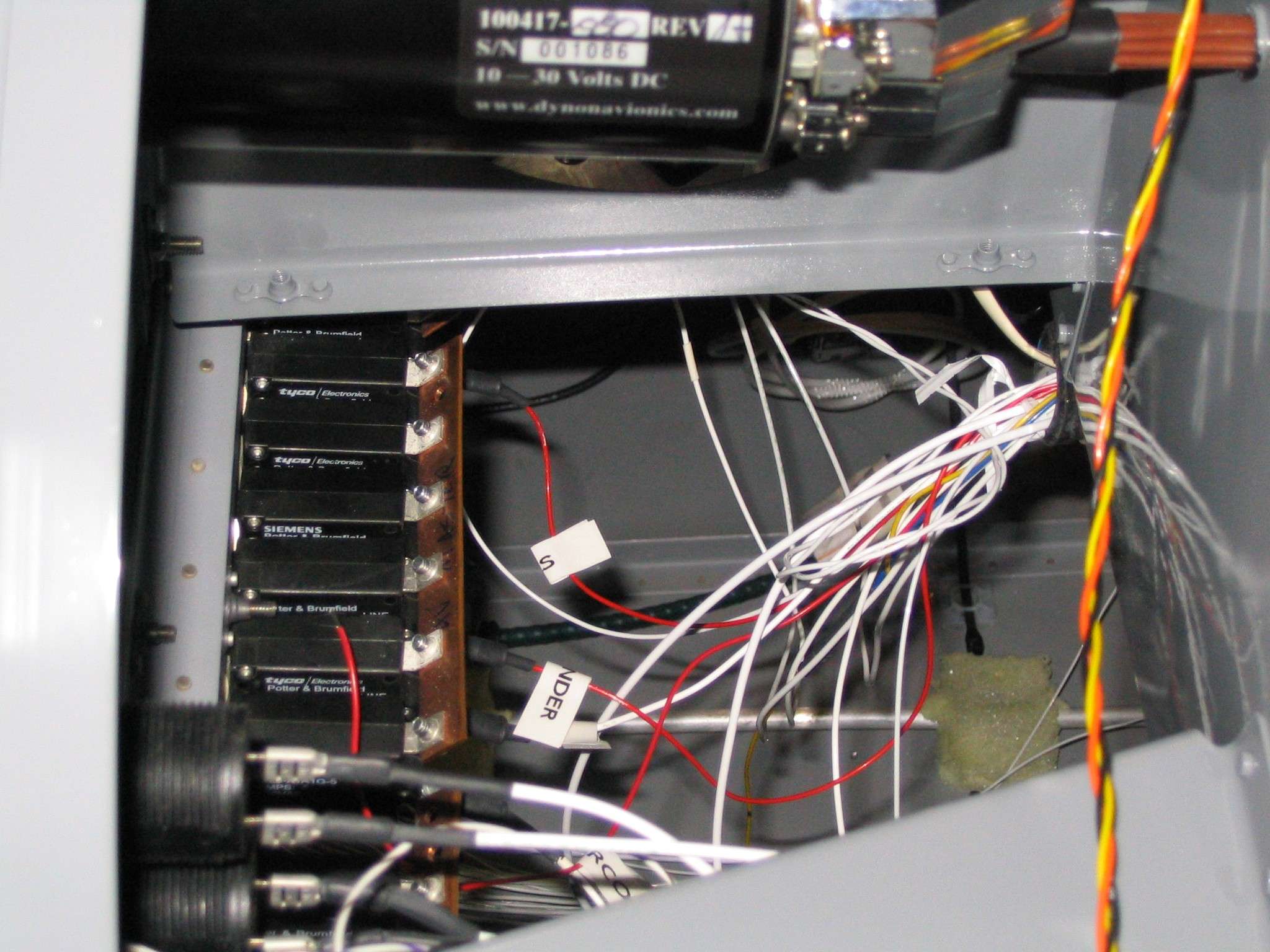
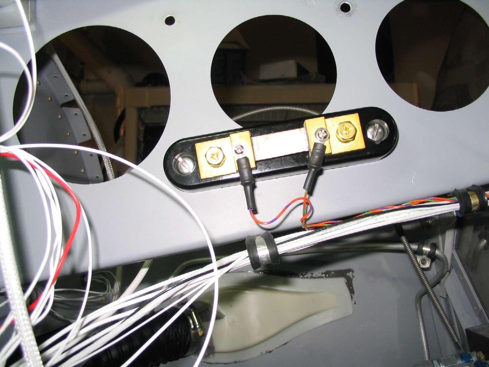
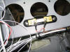
The ammeter
shunt was installed on the inside of the left forward rib, between the
sub-panel and the firewall. The small wires leading to this go to
the Dynon D10 EMS and the large wire from the contactor to the main bus
are yet to be installed. (9/17/06) E
The ammeter
shunt was installed on the inside of the left forward rib, between the
sub-panel and the firewall. The small wires leading to this go to
the Dynon D10 EMS and the large wire from the contactor to the main bus
are yet to be installed. (9/17/06) |
| |
|
Some times it is
the small things that help you feel like you are making real progress.
The thing that got me was finally connecting the master switch and "keep
alive" bus. No more running jumpers are required to play with the
instrument panel. Better yet, the cigarette lighter charger can now
be used to keep the battery fully charged. (10/1/06) |
| |
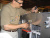
|
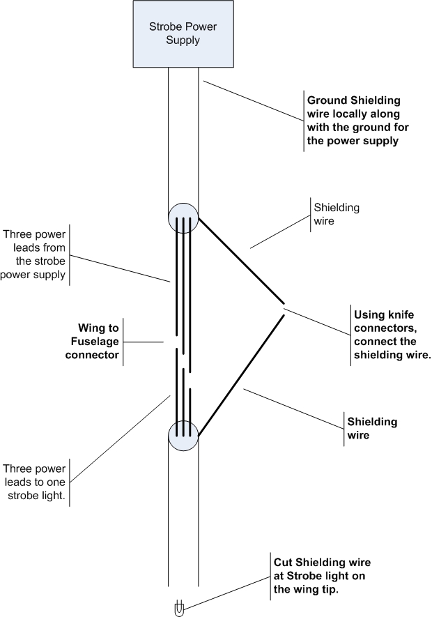
 F
Today I had good
intentions of working on something else, any thing else, but my friend Rradomir called to say he connected his strobes and tried them out for the
first time. Much to his dismay, he could hear the strobe discharging
through his intercom and radio. Even though he used a different
strobe system than I, he connected his in the same way with the power and
wire shield grounds run forward to the main ground block located on the
firewall. After much rooting around he pulled the grounds back and
grounded both items together at the power supply. Upon returning to
my workshop, I thought now might be a good time to connect my strobes and
try them for the first time, as well. With headphones on, I turned
on the radio master and the flipped the strobe switch. Here is one
word of advice, close your eyes if standing next to the strobes.
Since my wings aren't on the strobes were connected right next to where I
was standing on the side of the fuselage. My eye sight is slowly
returning to normal. F
Today I had good
intentions of working on something else, any thing else, but my friend Rradomir called to say he connected his strobes and tried them out for the
first time. Much to his dismay, he could hear the strobe discharging
through his intercom and radio. Even though he used a different
strobe system than I, he connected his in the same way with the power and
wire shield grounds run forward to the main ground block located on the
firewall. After much rooting around he pulled the grounds back and
grounded both items together at the power supply. Upon returning to
my workshop, I thought now might be a good time to connect my strobes and
try them for the first time, as well. With headphones on, I turned
on the radio master and the flipped the strobe switch. Here is one
word of advice, close your eyes if standing next to the strobes.
Since my wings aren't on the strobes were connected right next to where I
was standing on the side of the fuselage. My eye sight is slowly
returning to normal.
Sure enough, you could hear the
strobe discharge through the headsets. After fabricating a ground
point (Angle aluminum and a plate nut riveted to the underside of the
baggage compartment floor.)
the noise went away for me as well.
I suspect the long ground wires
make a very nice antenna and by grounding the locally and removing the
"antenna", the problem went away.
The simple
drawing should give you a better idea of how I wired the strobe grounds. (11/21/06) |
| |
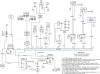
|
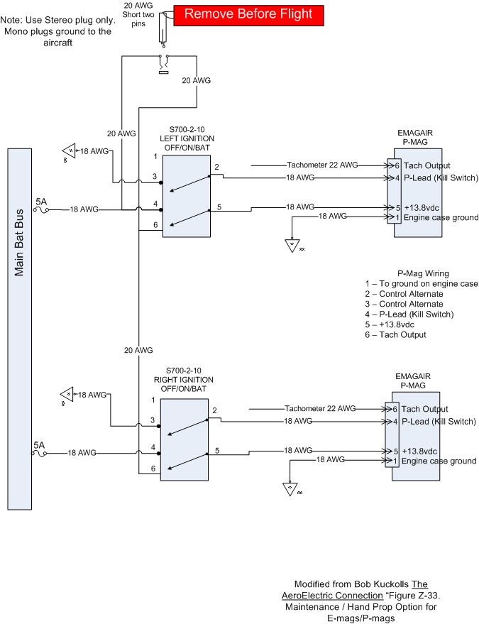
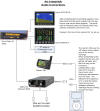
 E
It was time to wire up the P-mags.
Not a difficult task but an important one. Remember, it is just your
ignition system you are messing with. This diagram lists how I wired mine, you may have different requirements. One change I
made was replace the ground service switch with a 1/8" stereo jack and plug,
this eliminated the need for
warning light since the plug will have red "Remove Before Flight" streamer
attached to it. Note, I originally installed a mono jack only to
find out that one side of the jack shorts to ground. This forced me
to change it to a stereo plug and jack. If you have a P-mag breaker
pop when you turn on the master, you are probably shorting to ground
through this plug arrangement. (6/17/07) E
It was time to wire up the P-mags.
Not a difficult task but an important one. Remember, it is just your
ignition system you are messing with. This diagram lists how I wired mine, you may have different requirements. One change I
made was replace the ground service switch with a 1/8" stereo jack and plug,
this eliminated the need for
warning light since the plug will have red "Remove Before Flight" streamer
attached to it. Note, I originally installed a mono jack only to
find out that one side of the jack shorts to ground. This forced me
to change it to a stereo plug and jack. If you have a P-mag breaker
pop when you turn on the master, you are probably shorting to ground
through this plug arrangement. (6/17/07) |
| |
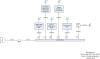
|
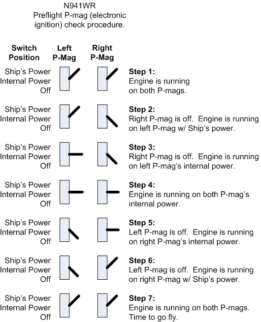
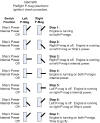 F
The preflight procedure with P-mags wired as I have is different than a
standard aircraft and this must be taken into account prior to each
flight. The basics are that each P-mag should be operationally
verified as functional when running on both ship's power and internal
power. This diagram displays how I perform this preflight task.
(5/18/08) F
The preflight procedure with P-mags wired as I have is different than a
standard aircraft and this must be taken into account prior to each
flight. The basics are that each P-mag should be operationally
verified as functional when running on both ship's power and internal
power. This diagram displays how I perform this preflight task.
(5/18/08) |
| |