Bill's Aircraft Factory
First
Flight
Trips
Horizontal
Stabilizer
Vertical
Stabilizer
Elevator
Trim Tab
Rudder
Wings &
Fuel Tank
Ailerons
Flaps
Fuselage
Page 1
Page 2
Page 3
Page 4
Engine & FWF
Page 1
Page 2
Page 3
Instrument Panel
Electrical System
Building in the Basement and Moving to the Airport
Dynon Autopilot
Installation
Things to Consider
Tools
Products
Tell me again
Helpful Links
Plane Pictures
FAQ's
E-mail:
bill (at)
repucci (dot) com
|
|
Things to Consider
Caution - Man running (with) power tools
|
Jump
to:
Goal
Bucking Bars
Riveting - Air pressures
Props
Work Space
Riveting Help
Wing Jig
Drawing Table
Priming
Marking edge distances
Builder's Log Book
Dimpling Tables
Clamps
Drilling Control Push Tubes
Removing plastic from large
pieces
Long reach dimpling tool
Knee/back/head pad
Long reach scribe
Aircraft Grade Pooper Scooper
Roll Around Fuselage Stand
How to accurately
measure the tail and wings
Fuel Valves
Reamers
Serial Numbers
Instrument Wire Runs
Van's Toolbox
Drilling out flush and Pop
Rivets
POH & Condition Inspection
Installing Adel Clamps
Inexpensive Engine Pre-Heater
Firewall mounted oil cooler
Ratchet Strap Tie Downs
|
| November 20, 2004: Let me start this section by saying that at
this early stage of the building process, this is just a place for me to
dream.
My goal is to build a simple and
reliable (ok, who doesn't want that in an airplane?) day and night VFR
craft. With that in mind, my RV-9 will not be loaded down with
unnecessary instruments and radios. Remember, the first and only
aircraft I have ever owned was a 1941 T-Craft, BC12/65 with no electrical
system. Just the thought of having a radio that doesn't require
batteries seems odd to me. Anyway, when
building the wing Van's tells you to drill in the spar web to accommodate
their pitot tube, if you plan on using a heated pitot tube or one from
Dynon, do NOT drill this hole as you will only have to fill it in later.
Back to top |
| |
|
December 9, 2004
 F
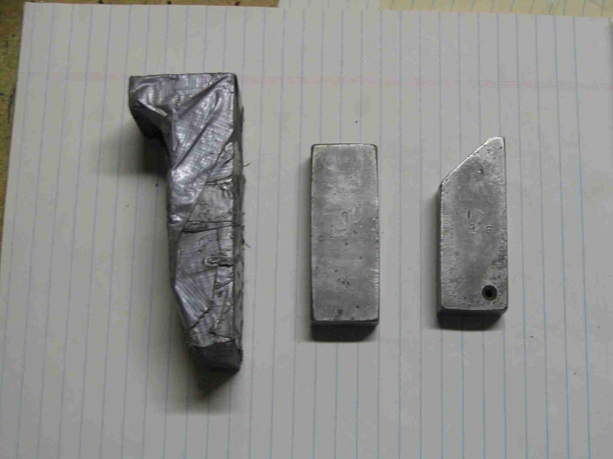
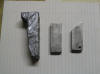
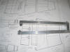
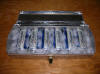
Bucking bars are one of the simplest, yet most import tools you will
collect. The tool on the left is a standard bucking bar that I'm
sure every builder of metal airplanes has. The two bucking bars on
the right were given to me by a neighbor who is a maintenance director for
one of the major airlines. They are made from tungsten and weigh almost as
much as the bigger, cast iron bar. 1 lb, 13 oz for the cast iron
bar and 1 lb, 3 oz for the rectangular tungsten bar. The smaller
bars are so much more convent than the bigger cast iron bars and fit in
small places. I sure wish I had a set of these when I started on the
Horizontal Stabilizer! F
Bucking bars are one of the simplest, yet most import tools you will
collect. The tool on the left is a standard bucking bar that I'm
sure every builder of metal airplanes has. The two bucking bars on
the right were given to me by a neighbor who is a maintenance director for
one of the major airlines. They are made from tungsten and weigh almost as
much as the bigger, cast iron bar. 1 lb, 13 oz for the cast iron
bar and 1 lb, 3 oz for the rectangular tungsten bar. The smaller
bars are so much more convent than the bigger cast iron bars and fit in
small places. I sure wish I had a set of these when I started on the
Horizontal Stabilizer!
I highly recommend you get a set of these, if
you are going to do any type of riveting! Unfortunately, I have been
unable to find a source for tungsten bar stock so I can't help you locate
a bar or two. Back to
top |
| |
|
Riveting (Added 4/2/08) I
usually don't like to link to other web sites as links change and/or go
away but if you haven't checked out Dan Checkoway's web site,
www.rvproject.com,
you must do so. On his site he has
an entire page dedicated to riveting. This should be required
reading prior picking up a rivet gun. The following is a shameless
cut and paste job from that page and is posted here for quick reference:
Suggested Operating Pressures
As I mentioned, I use different operating air pressures at the rivet
gun for various different sizes of rivets and material. I put this table
of information together based on my experience. Keep in mind that I use an
Avery 3X rivet gun, and that your results may vary (some builders
opt for a 2X gun, which may behave very differently). Also, you can
vary the duration of driving the rivet to compensate for pressure in many
cases. For example, instead of cranking the psi up, you can drive the
rivet for a longer period of time. Anyway, here are the "baseline"
settings I use for reference:
AN426 Rivets:
-
| Rivet Type |
Air Pressure |
Duration |
| AN426AD3-3 to 3-4 |
34 psi |
1 second |
| AN426AD3-4.5 to 3-5 |
37 psi |
1 ½ seconds |
| AN426AD3-6 plus |
40 psi |
1 ½ seconds |
| AN426AD4-4 to 4-5 |
45 psi |
1 second |
| AN426AD4-6 to 4-9 |
50 psi |
1 ½ to 2 seconds |
AN470 Rivets:
-
| Rivet Type |
Air Pressure |
Duration |
| AN470AD4-4 to 4-5 |
60 psi |
1 second |
| AN470AD4-6 to 4-7 |
60 psi |
1 ½ seconds |
| AN470AD4-8 to 4-9 |
75 psi |
1 ½ seconds |
| AN470AD4-9 plus |
80 psi |
1 ½ to 2 seconds |
|
| |
|
Prop it up!
(updated 8/2/05)
What prop should I use?
Metal, wood, composite, or a combination? Two or three blades?
All of these questions need to be answered by the builder, in this case,
me. Each type of blade construction have both benefits and
drawbacks. I like flying with wood props because they transmit less
vibration to the airframe but they require more maintenance than metal
props. Mostly they have to be re-torqued every so often. This
isn't a big deal but is something you need to be aware of. Some
people like wood props because in the event of a prop strike, you won't be
rebuilding your engine. Metal props are good in the rain, don't need
to be re-torqued, are usually more efficient at turning engine
power/fuel/noise into thrust. There are more reasons to
select one type of prop over another, if you want to know more, a Google search will give you more info than you can digest, along with a
lot of folklore. Since my -9 will be powered by an O-290, I won't
even go into a diatribe regarding constant speed props.
I managed to get in touch with
gentleman from Canada who completed an O-290 powered RV-9A. He
was flying with a 70" by 70" Colin Walker wood prop and was turning 155
mph indicated / 170 mph true. He spoke very highly of the
engine/prop/airframe combination and was surprised more -9/-9A builders
weren't considering that option in the US and Canada. (Apparently
that is the engine of choice in Europe.)
Originally I thought I would use
a Colin Walker prop but I couldn't locate him and heard a rumor he is no
longer making props. If this is not true, please email me.
After doing some research, talking to people and seeing one or two in
person I have decided to have a
Catto prop custom
made for my -9. Craig Catto believes a 68" diameter by 66" pitch two
bladed prop will get me to that magic 175 mph cruise speed without giving
up too much climb performance. I can deal with 175 mph from a 135 hp
engine and its resulting fuel burn.
Back to
top |
| |
|
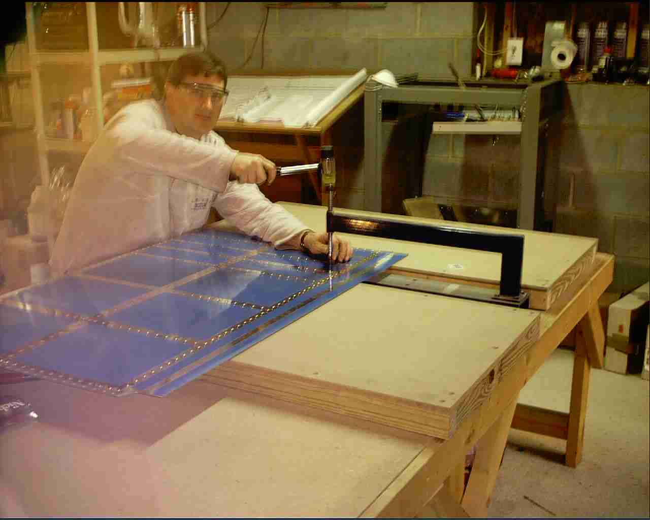
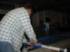
December 19, 2004 - Work Space
Think about your workshop before you start.
Van's mentions this on his web site, take it to heart. I started on
my -9 in my basement workshop. It was good as a shop goes, dry and
roomy. I went through the trouble of ringing the shop with
electrical outlets, with every other one on a different circuit so I
wouldn't have to worry about blowing a fuse then I hung up a bunch of shop
lights and still wish I had put more and need to move some of the ones I
installed to eliminate the shadows cast on some of my bench tools.
Maybe someday I'll get to that last task.
After spending a year and a half working in
the basement without any insulation and the only environmental control
being an over worked dehumidifier I finally decided to insulate the
place. Where I live in NC, it can be below freezing in the winter
and in the upper 90's with the humidity in the upper 90's during the
summer. Not
really conducive to spending a lot of time there. Having grown up in
Mid-Michigan, the cold didn't bother me at all but the heat and humidity
was unbearable. My wonderful wife and part time bucking partner grew
up in Texas and Oklahoma and just doesn't deal well with the cold so I
knew if I was going to get her in the basement for year two I need to
insulate the place so my space heaters would have a chance to keep her
fingers working.
My house was built on a hill so 1/2 the
basement walls were cinder block and the other half is 2x4 construction
with the studs being on 12" centers because they had support a two story
house. This meant that I had to buy 24" wide R-13 fiberglass
insulation and cut each baton to fit and then drywall. Not a
difficult task (two days to complete and yes, I have hung drywall before,
so there was no learning curve for me.) but one that required moving
tools, equipment, and airplane parts. I highly recommend taking care
to make your shop comfortable before you start. Heck, I found that
when my shop radio died, I didn't spend as much time working down there so
I replaced the home stereo and moved the old one down to the basement, now
both the wife and I are happy.
Oh, the results of the newly insulated
basement, Nora will come downstairs, pull up a book and read while I chip
away on the -9. Best of all, she is right there, if I need her to
hold anything or buck a rivet. What a woman!
Back to
top
Riveting Help
At some time you are going to need help
driving rivets and your usual riveting partner won't be available. I
had always thought it was more difficult to teach someone to drive rivets
than to buck them. BOY was I ever wrong. It has been my
experience that the person with the bucking bar is more important than the
person with the gun. I teach each new rivet driver to put the rivet
in, put a small piece of tape over it, place the gun on the rivet, hold
the rivet set in place with their free hand so it doesn't move then gently
squeeze the trigger.
Trying to teach someone to keep a bucking bar
on a rivet without pushing the rivet out while holding the bucking bar in
the correct place has prove to be rather difficult.
That is my $.02 on the subject, others might
have had different experiences.
Back to
top |
|
|
|
January 4, 2005
- Wing Jig
 E
I received an email asking how I managed to keep
the vertical posts in alignment while I worked on the wings. This
picture shows my solution. The bracket was screwed on to the bottom
of my vertical 2x4 posts. E
I received an email asking how I managed to keep
the vertical posts in alignment while I worked on the wings. This
picture shows my solution. The bracket was screwed on to the bottom
of my vertical 2x4 posts.
When screwing the posts together, I checked the
end grain and made sure they were back to back, that way the post wouldn't
warp. The end of the 2x4's should look something like this
[)))][(((].
The fear of the posts warping was also the reason I didn't use a 4x4 as
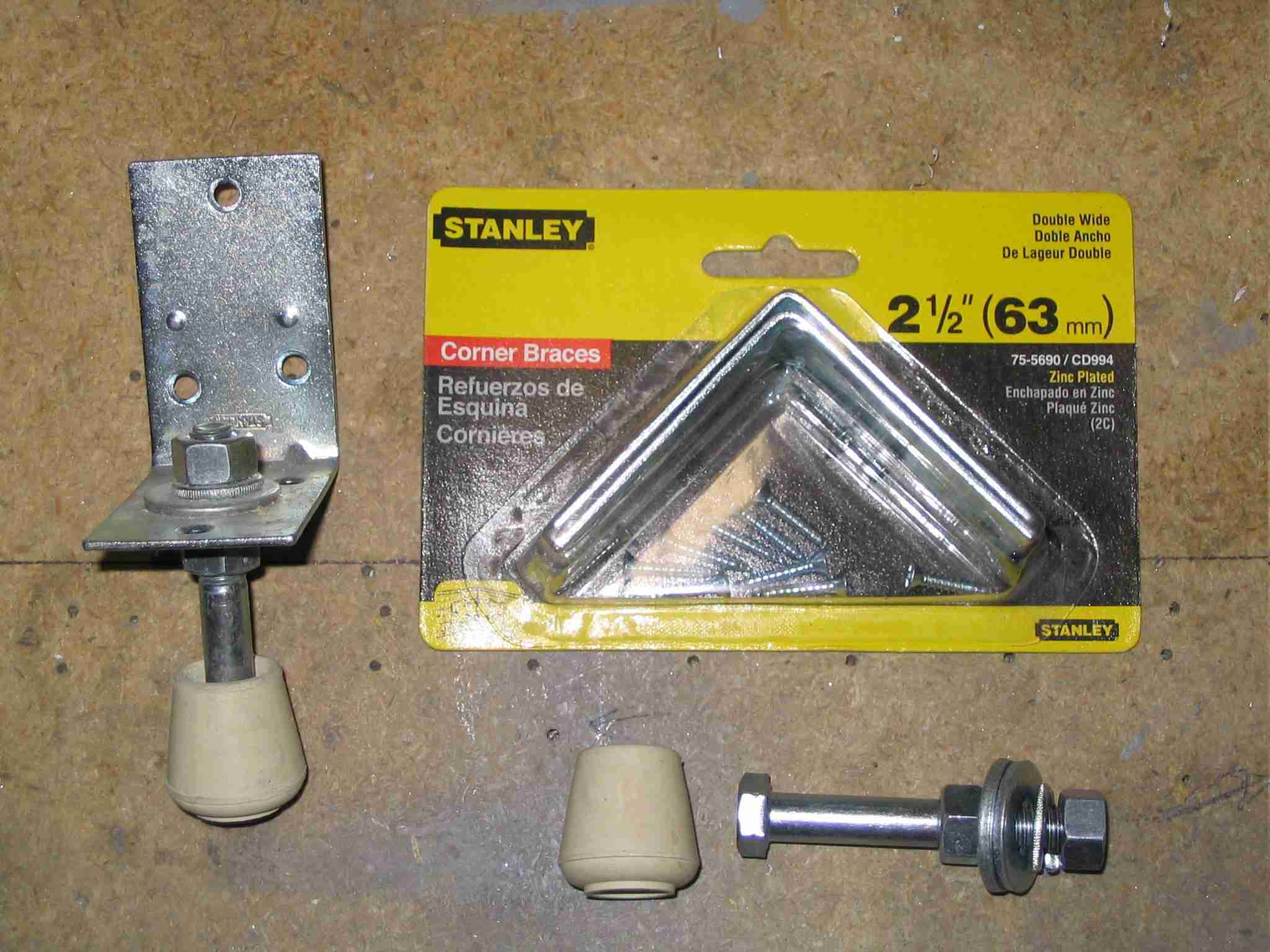
specified by the instructions. Initially I was going to use two
"feet" on each post but after installing one and lowering the foot, the
posts wouldn't move, even after someone ran into them. (I'm so happy
to have those things out of the middle of my basement!)
After installing the posts and making sure they
were perfectly vertical the next trick is to get the horizontal arms at
exactly the same height. I accomplished this by using a long section
of clear vinyl tubing about the size of a garden hose. I filled the
tubing with water and worked all the bubbles out. I then duck taped
one end of the hose to each vertical post. The water will seek it's
own height and when it did, I measured up (or was it down?) from that
"head" and marked where the horizontal arms should go. It then was a
simple task to attach the arms using a standard carpenter's level to make
sure they were "square".
Back to
top |
| |
|
January 23, 2005
- Drawing Table
Last weekend I was paid a visit by one of EAA
309's Technical Counselors. If you have one available to you, take
advantage of his or her expertise. It is well worth it, more so when
the FAA DAR asks to see the TC forms and you have to explain that you
don't have any.
 F
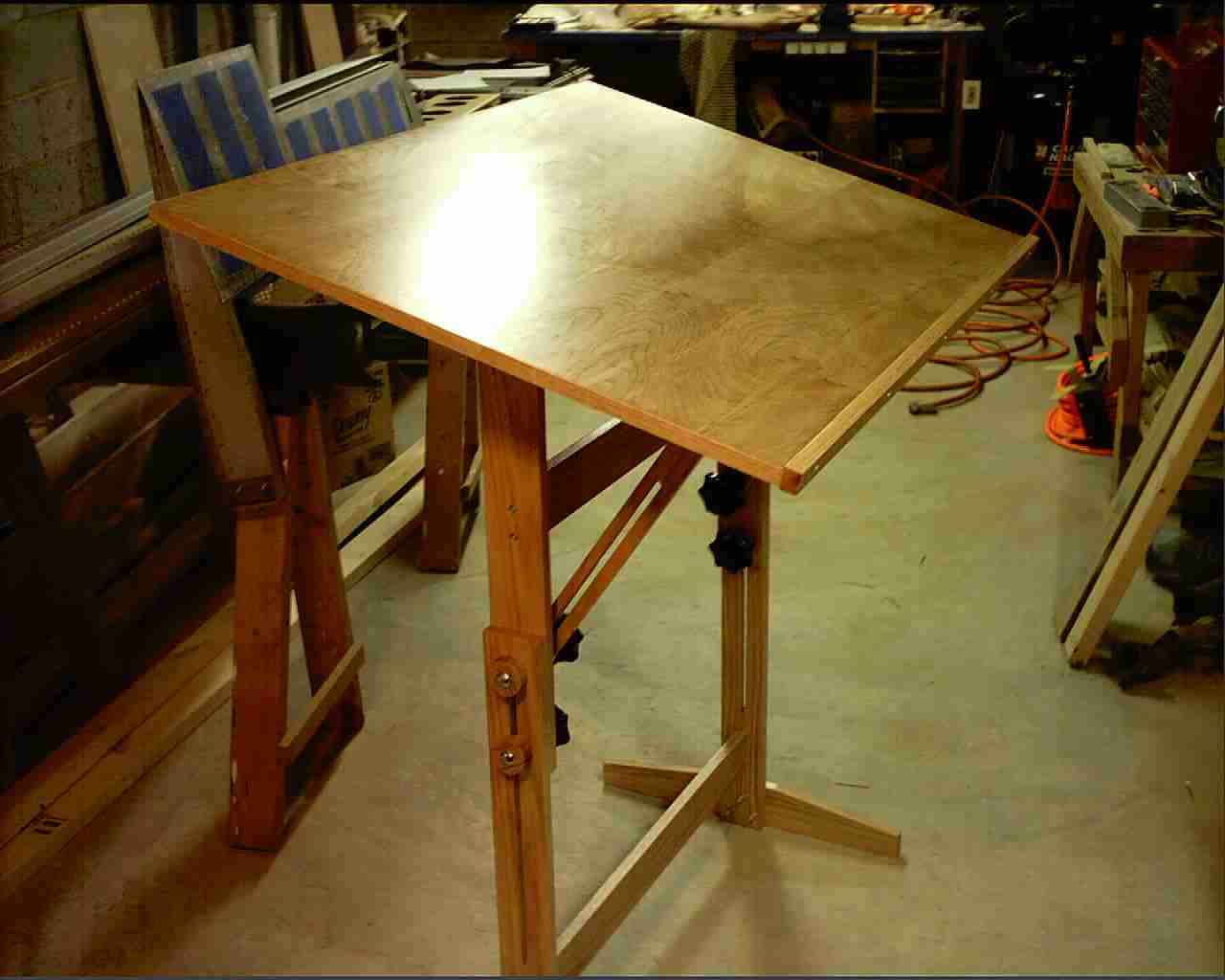
When building, you will need a place to put all those wonderful drawings.
The TC told me he hung his drawings on the wall around his shop.
That way he could look at more than one of them at a time. I built
this drafting table to hold mine but whatever you do, you will need
someplace to hold them for viewing. You can find the plans for the
table on John Petersen's site:
http://www.petersenart.com/drafting_table/. F
When building, you will need a place to put all those wonderful drawings.
The TC told me he hung his drawings on the wall around his shop.
That way he could look at more than one of them at a time. I built
this drafting table to hold mine but whatever you do, you will need
someplace to hold them for viewing. You can find the plans for the
table on John Petersen's site:
http://www.petersenart.com/drafting_table/.
 E
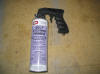
Ok, you've decided to build an aluminum airplane.
You've searched the net on corrosion protection and are wondering what
other people are doing. I do not guarantee that my method is the
best. I believe the best is epoxy priming but I'm lazy and cleaning
the spray gun every time I prim a part sounds like a pain. What I
did was alumniprep'ed, alodined, then finally sprayed the parts with cans
of Self Etching Primer. It seems to work but check back with me in
20 years and I'll tell you how it is holding up. To make life easier
on my index finger, I bought the pistol grip you see in the picture from
Home Depot. E
Ok, you've decided to build an aluminum airplane.
You've searched the net on corrosion protection and are wondering what
other people are doing. I do not guarantee that my method is the
best. I believe the best is epoxy priming but I'm lazy and cleaning
the spray gun every time I prim a part sounds like a pain. What I
did was alumniprep'ed, alodined, then finally sprayed the parts with cans
of Self Etching Primer. It seems to work but check back with me in
20 years and I'll tell you how it is holding up. To make life easier
on my index finger, I bought the pistol grip you see in the picture from
Home Depot.
Back to
top
|
|
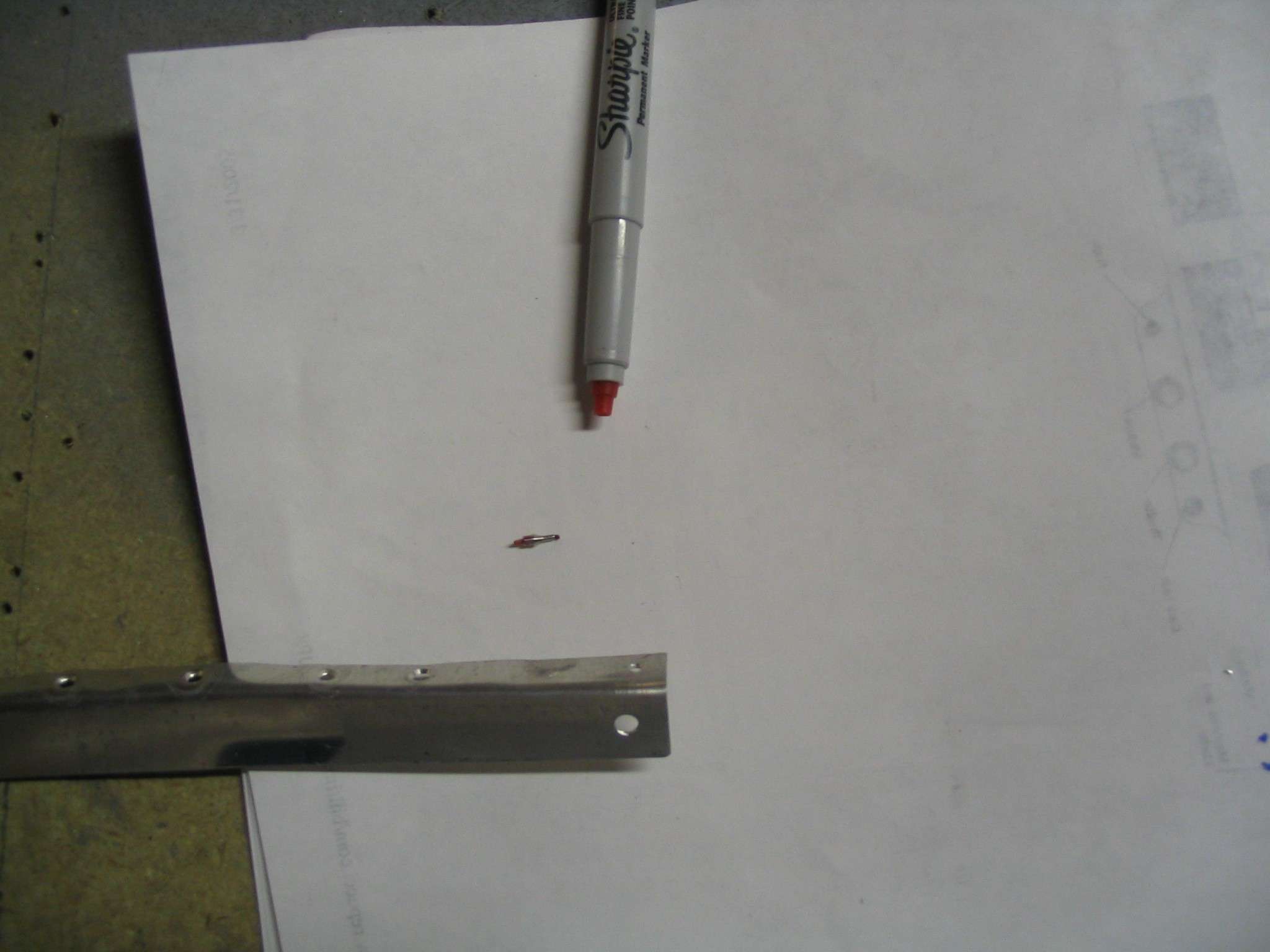
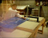
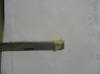
January 29, 2005 - Marking Edge Distances
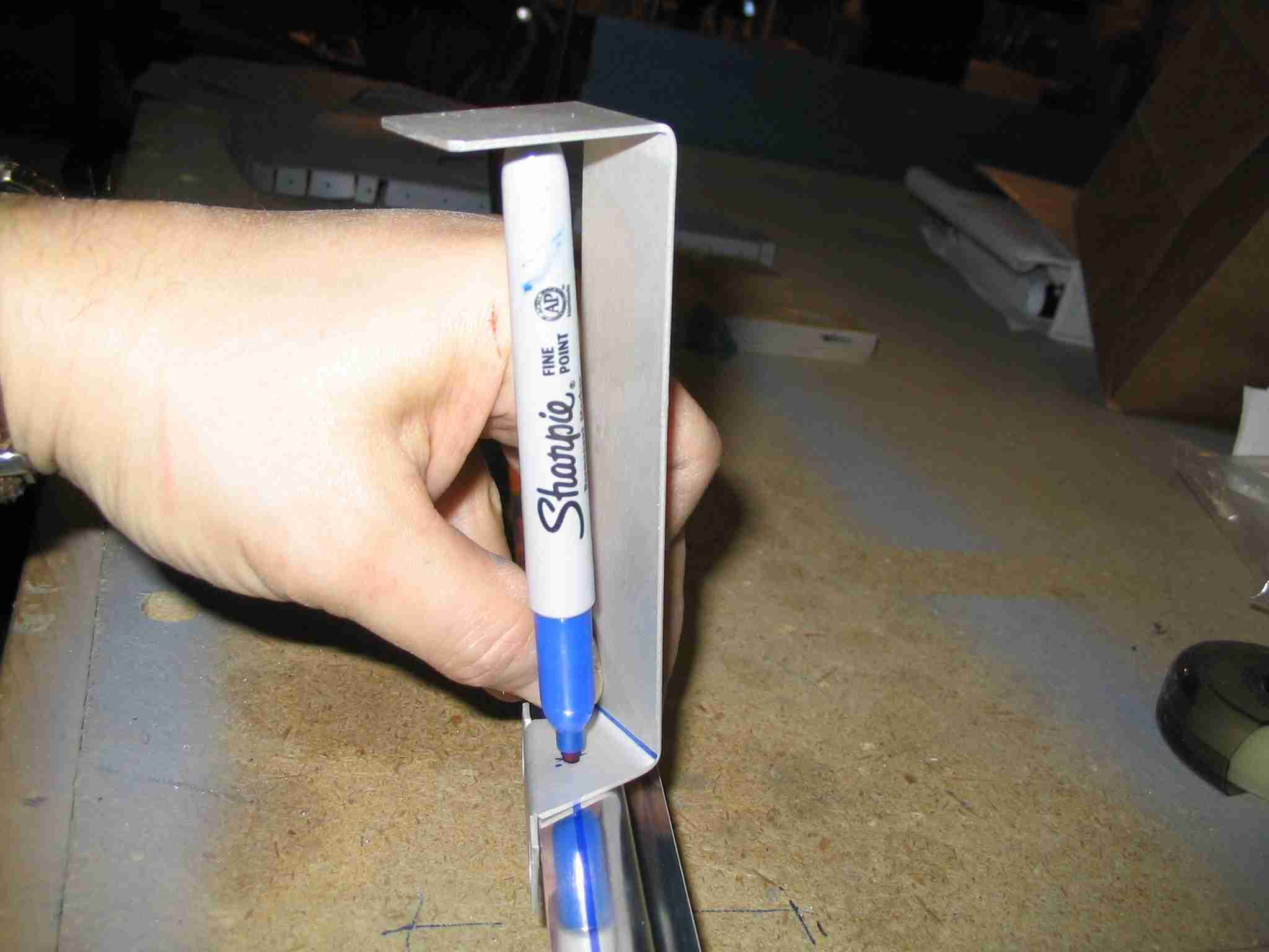
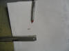
 F
This evening while fitting the four "J" cannel to the aft fuselage I
realized I had to mark a line down the length of each "J" cannel.
Now you have to mark these "J" cannels for the wing as well and Avery's
sells a neat little tool to hold a Sharpie but I'm too cheap to spend the
money on their tool an besides, I wanted to mark the cannels this evening
and not wait for the order to arrive. Looking around the shop for a
chunk of wood that I could cut and drill I noticed these funny little
straps with a small flange bent up on one end in my scrap bucket and a
light bulb light up over my head. I can take one of those, measure
in the appropriate distance, drill a hole for the tip of a sharpie and
then bend the thing up to hold the other end in place. This picture
is what I made and it works great. You don't have to bend the flange
at a funny angle like mine. As I said earlier, this strap came out
of my junk pile and I can't even remember what it came from. Why
didn't I think of this earlier? F
This evening while fitting the four "J" cannel to the aft fuselage I
realized I had to mark a line down the length of each "J" cannel.
Now you have to mark these "J" cannels for the wing as well and Avery's
sells a neat little tool to hold a Sharpie but I'm too cheap to spend the
money on their tool an besides, I wanted to mark the cannels this evening
and not wait for the order to arrive. Looking around the shop for a
chunk of wood that I could cut and drill I noticed these funny little
straps with a small flange bent up on one end in my scrap bucket and a
light bulb light up over my head. I can take one of those, measure
in the appropriate distance, drill a hole for the tip of a sharpie and
then bend the thing up to hold the other end in place. This picture
is what I made and it works great. You don't have to bend the flange
at a funny angle like mine. As I said earlier, this strap came out
of my junk pile and I can't even remember what it came from. Why
didn't I think of this earlier?
Back to
top |
|
| |
|
February 20,
2005 - Builder's Log Book
 E
Log books are such a pain to maintain and I'm such a bad
writer that I thought I would put my computer skills to use
for maintaining my log book. E
Log books are such a pain to maintain and I'm such a bad
writer that I thought I would put my computer skills to use
for maintaining my log book.
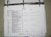
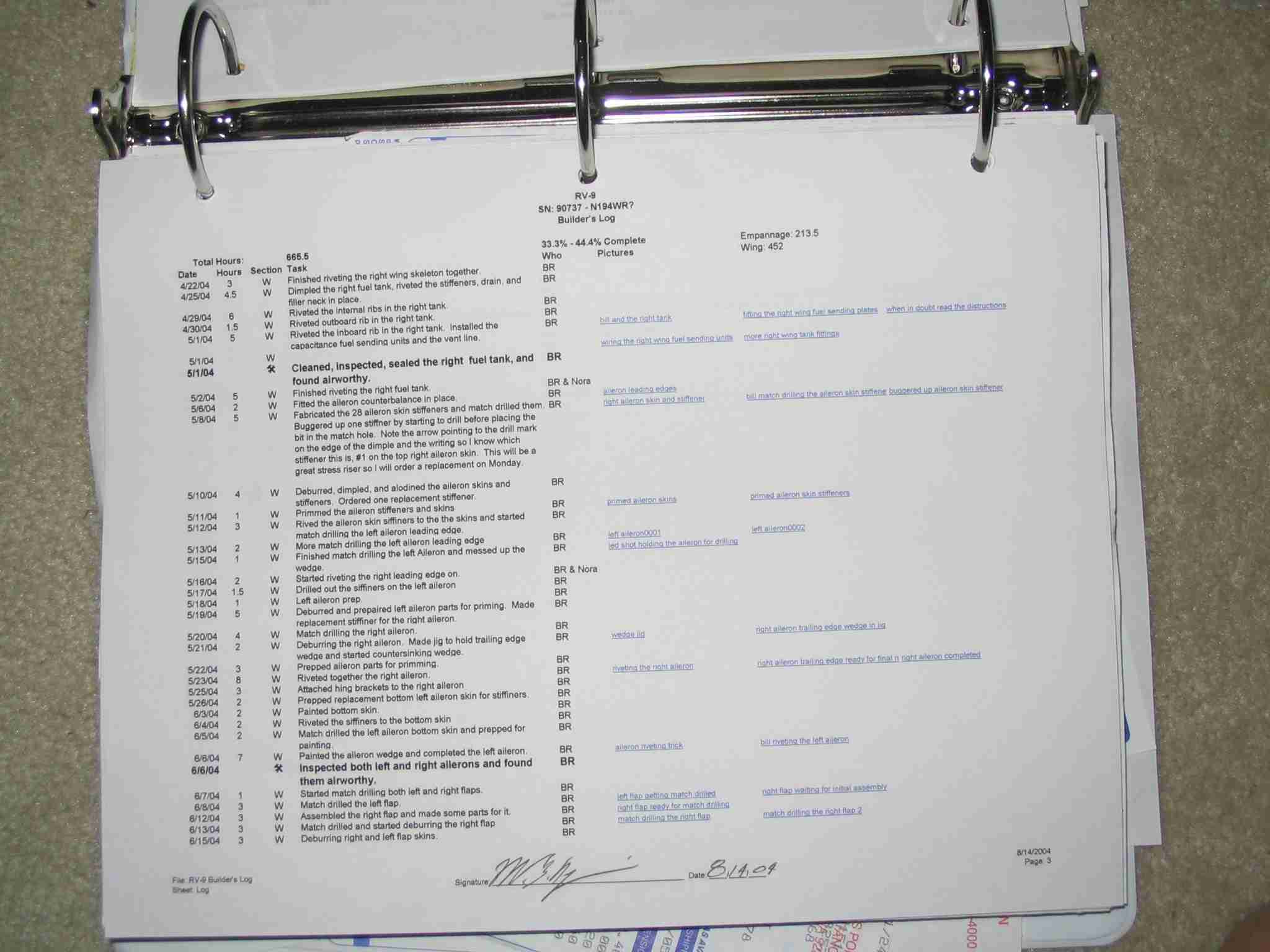
E
Excel is such a great tool! Here is what my log pages
look like. Excel even has a "Hyper Link" feature that
lets you link a cell to a picture. While looking at my
log in Excel I can click on the link and the picture will pop
up.
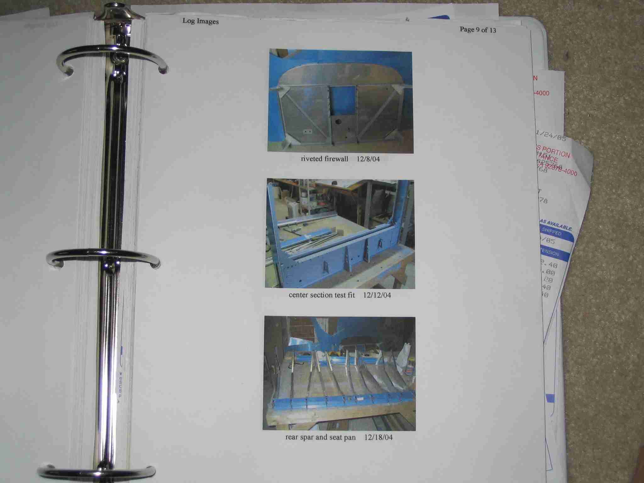
 E
There is a tab on the worksheet that will produce the HTML
code to print and label the pictures for my builders log once
you copy and paste the code to a text editor and open it in
your web browser. E
There is a tab on the worksheet that will produce the HTML
code to print and label the pictures for my builders log once
you copy and paste the code to a text editor and open it in
your web browser.
This is a
sample of the
spreadsheet I created. If you are going to use this,
you will need to modify it to match the directory structure on
your computer. Please don't call or email me with Excel
questions. I am very good with this tool but trying to
walk someone through a computer issue via email is a
challenge.
Here is a
sample of
the HTML code I used to print the images. Save the
file on your drive and open it using the text editor.
You will need to leave the header section in place and paste
the picture producing text (first three columns from the
"Image Printing" tab on the spreadsheet) in to it, save the
thing, and then open it IE or whatever web browser you are
using.
Back to top |
| |
|
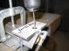
February 24,
2005 - Dimpling Tables
Before you start
using a C-Frame tool to dimple your skins you will want to
build something to hold the skins level with the flat part of
your dimple dies. Without this you run the risk of
damaging the skins if they are not perpendicular to the center
of the die.
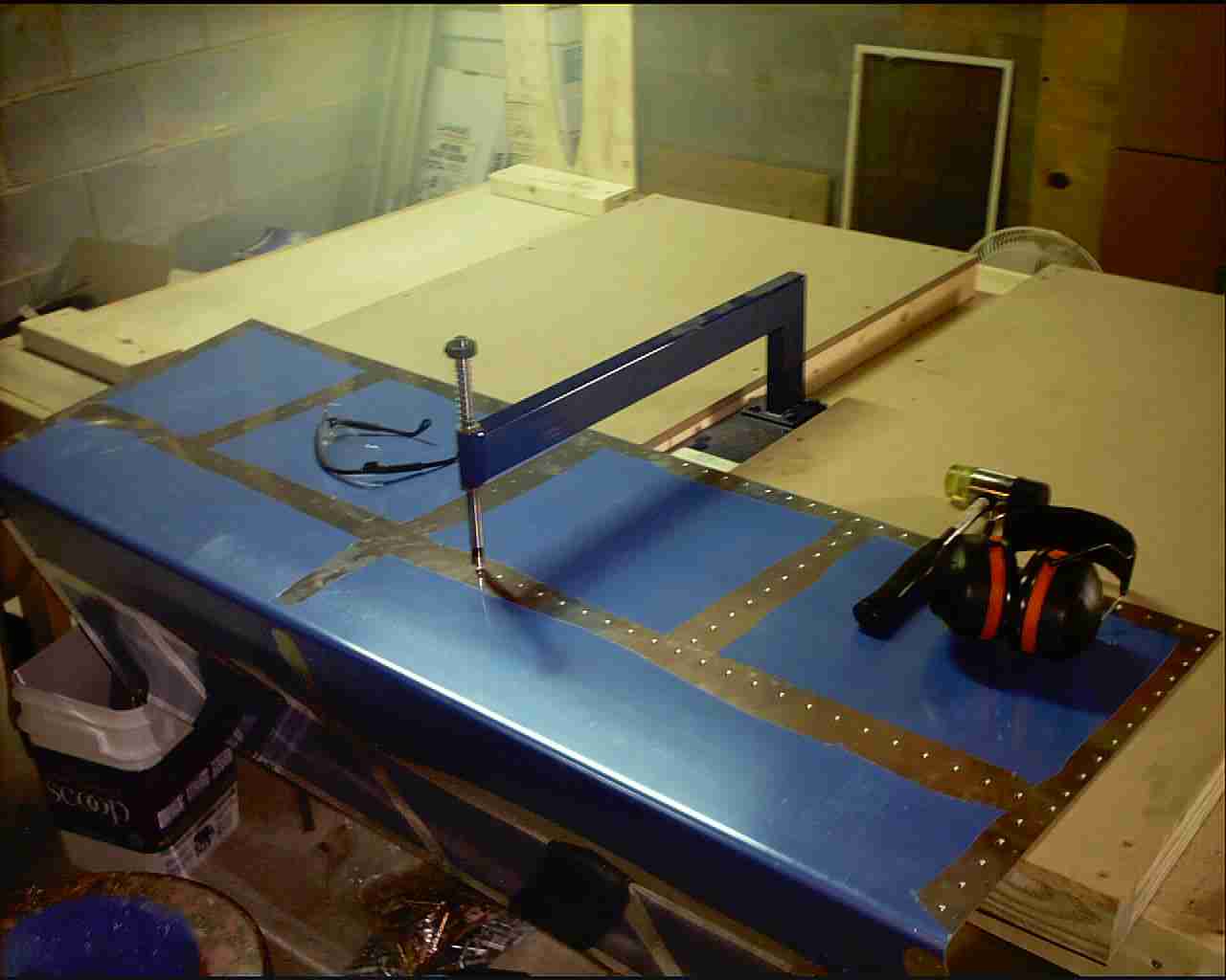
F
This was my first attempt at a solution. Needless to
say, it didn't work out very well and was a real pain when
working with the bigger skins. Someone suggested I use
two tables, one on either side of the C-Frame. I sure
wish I could remember who suggested that as I would like to
thank him.
 F
The tables I built use particleboard and some 2x4's I had
laying around. The 2x4's had to be ripped lengthwise so
the tables would be at the correct height. One of the
advantages to this setup is you can push the tables off the
edge of your work surface so you can get to those pesky HS
skins F
The tables I built use particleboard and some 2x4's I had
laying around. The 2x4's had to be ripped lengthwise so
the tables would be at the correct height. One of the
advantages to this setup is you can push the tables off the
edge of your work surface so you can get to those pesky HS
skins
 F
Another advantage is you can slide the C-Frame back and forth
while the skin remains in one place. My preferred method
is to put the male die on top and hold it in place while I hit
it with a hammer. F
Another advantage is you can slide the C-Frame back and forth
while the skin remains in one place. My preferred method
is to put the male die on top and hold it in place while I hit
it with a hammer.
 F
Here is what happens if you don't hold the die in the hole and
the skin moves just before the hammer falls. This skin
was replaced. Don't get discouraged, I figure when the
weight of my ruined parts equals 1/4 the empty weight of the
airplane I'll be ready for the first flight. F
Here is what happens if you don't hold the die in the hole and
the skin moves just before the hammer falls. This skin
was replaced. Don't get discouraged, I figure when the
weight of my ruined parts equals 1/4 the empty weight of the
airplane I'll be ready for the first flight.
Back to top |
| |
|
April 10, 2005 - Clamps
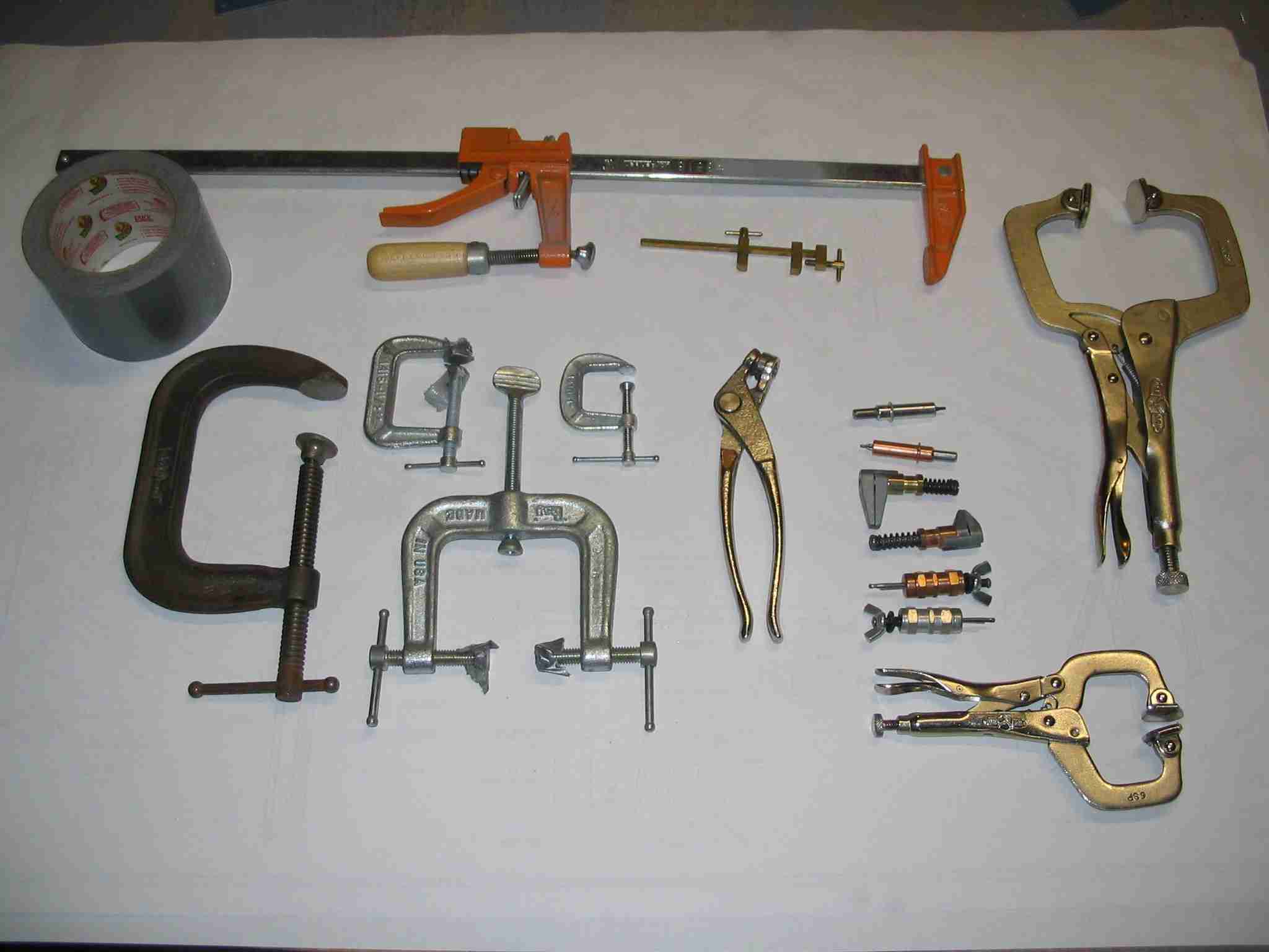
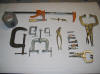 E
Every project, be it a boat, plane, car, or drafting table
requires the use of some type of clamp. E
Every project, be it a boat, plane, car, or drafting table
requires the use of some type of clamp.
I have a number of
different size C clamps, bar clamps, cleco clamps, Vise-grip
clamps, and Duct Tape. Yes, you read that correctly,
Duct Tape. When using C clamps protect the aluminum with
either pieces of wood or duct tape.
There have been a
number of times when something needed to be held in place and
my arms just weren't long enough to hold it in place and there
was nothing to clamp it to. The
trick it to line up the part correctly and then hold it in
place with Duct Tape. Since the tape can't hold the part
very tightly I usually just mark it with spinning drill bit,
remove the part and finish drilling it on the bench then
reinstall it using clecos.
Don't forget you can
make your own clamp with some scrap wood and sheet rock
screws. I can't tell you how many parts I have held in
place using this method.
Back to top |
| |
| |
|
April 14, 2005 -
Drilling Control Push
Tubes
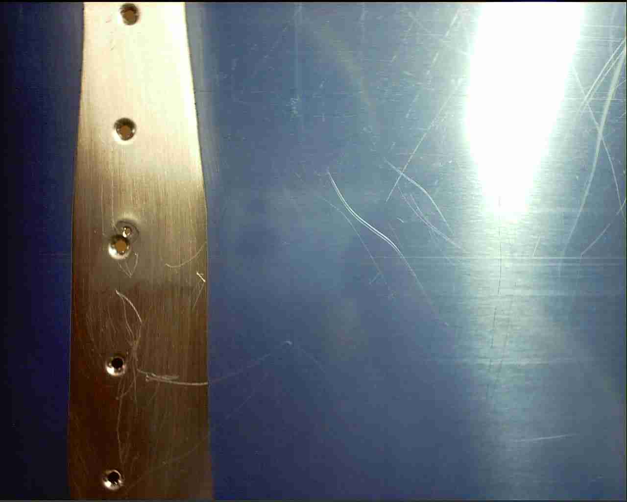
 F
At some point you are going to need to drill rivet holes in
push tubes used to active the ailerons and elevators. I
drilled my first set by hand and although they are airworthy I
just don't like the way they came out. This is a sample
I drilled using the drill guide. Notice how nicely
spaced the holes are. F
At some point you are going to need to drill rivet holes in
push tubes used to active the ailerons and elevators. I
drilled my first set by hand and although they are airworthy I
just don't like the way they came out. This is a sample
I drilled using the drill guide. Notice how nicely
spaced the holes are.
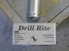
 F
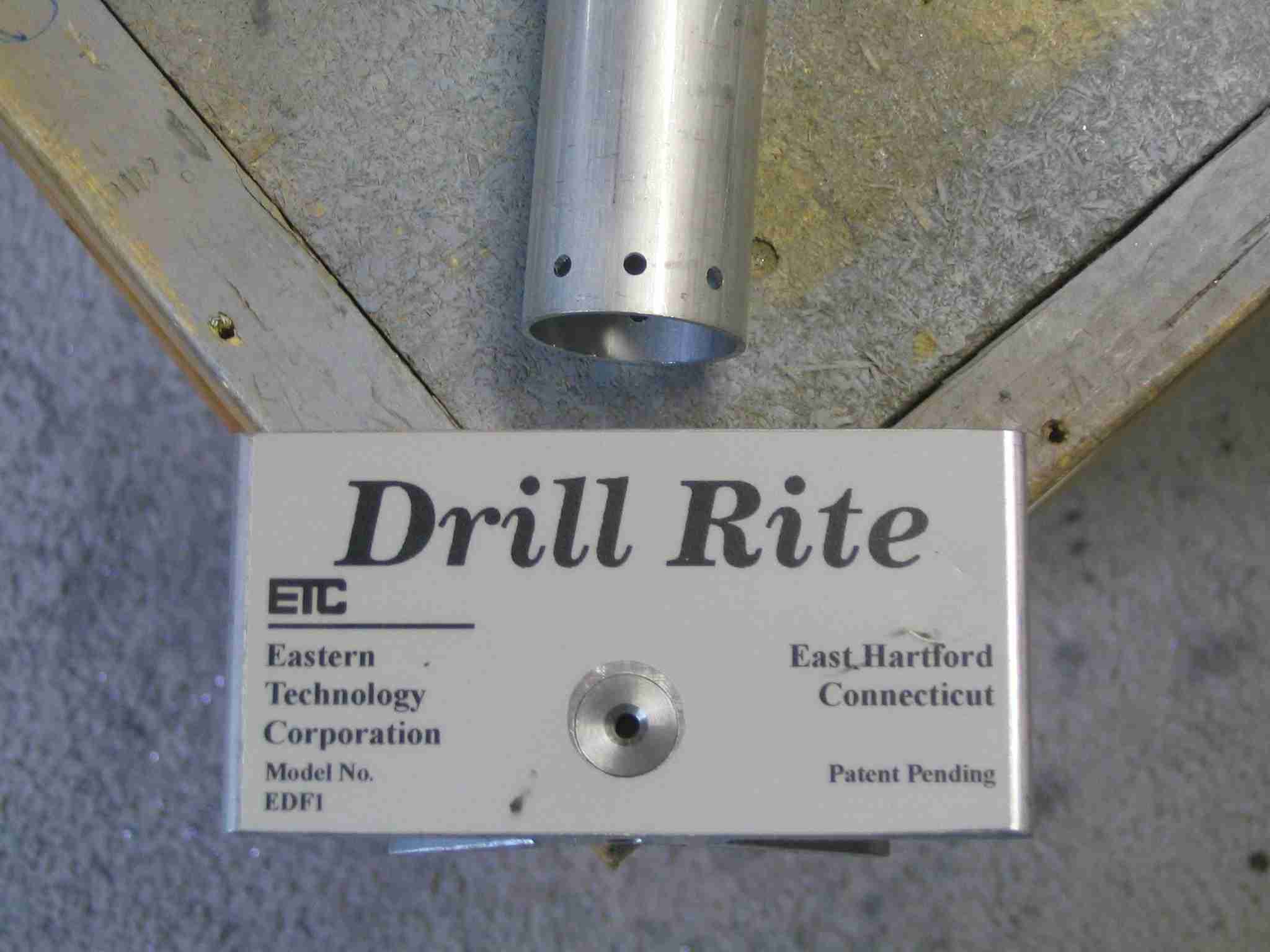
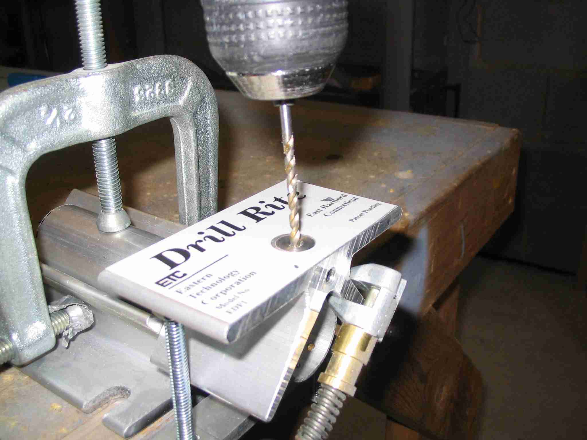
This picture illustrates how to get good results with the
Drill Rite drill guide. I clamped the tube in a "V"
block then set the edge distance to the hole using a cleco
clamp. (Note, the cleco clamp is not clamping the tube
in place.) The Drill Rite is clamped on the tube using
the wing nuts provided and the holes are drilled with a hand
drill. It can't get much easier than that! F
This picture illustrates how to get good results with the
Drill Rite drill guide. I clamped the tube in a "V"
block then set the edge distance to the hole using a cleco
clamp. (Note, the cleco clamp is not clamping the tube
in place.) The Drill Rite is clamped on the tube using
the wing nuts provided and the holes are drilled with a hand
drill. It can't get much easier than that!
The Drill Rite
arrived but did not include a bushing for 1/8" drill bits.
A short call to the
Eastern
Technology Corporation in East Hartford, CT had one in my
mail box in less than a week. The owner of the company
helped a friend build an RV-4 a few years ago and is well
aware of the tool market for homebuilder's and was more than
willing to help me out. In fact, it sounds like the jig
may start shipping with the 1/8" drill bushing just for us RV
builders.
US Industrial
Tool Company sells the guide for $48 and they are listed
under "Precision Drill Guide",
part number TP974.
Back to top |
| |
|
April 17, 2005 -
Removing plastic
from large pieces
 E
It took me awhile to figure out how to get the plastic off
some of the larger skins. The best method I have found
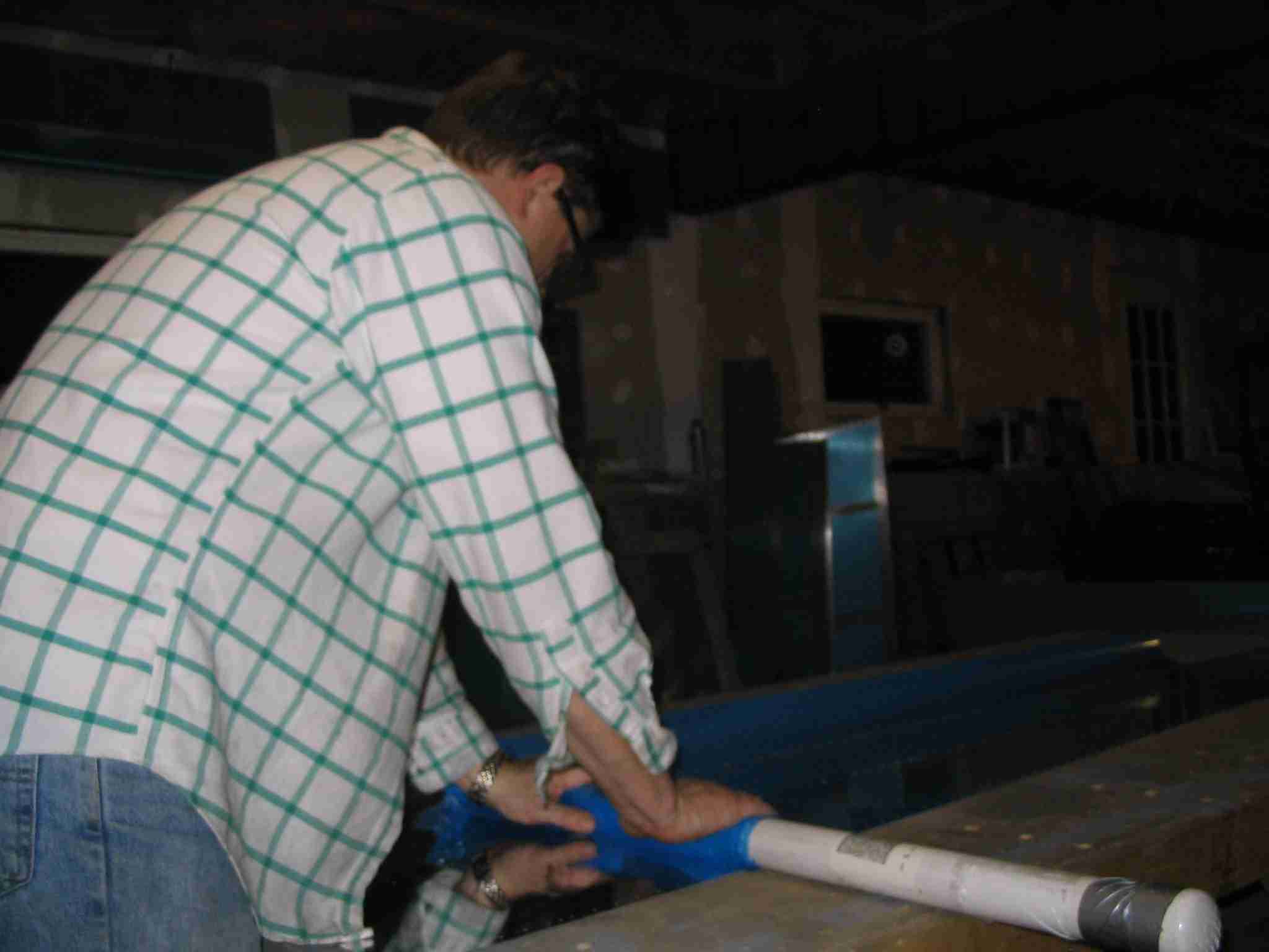
is to roll it up on section of 1.5 - 2" diameter PVC pipe. E
It took me awhile to figure out how to get the plastic off
some of the larger skins. The best method I have found
is to roll it up on section of 1.5 - 2" diameter PVC pipe.
Back to top |
| |
|
May 30, 2005 -
Long reach dimpling tool
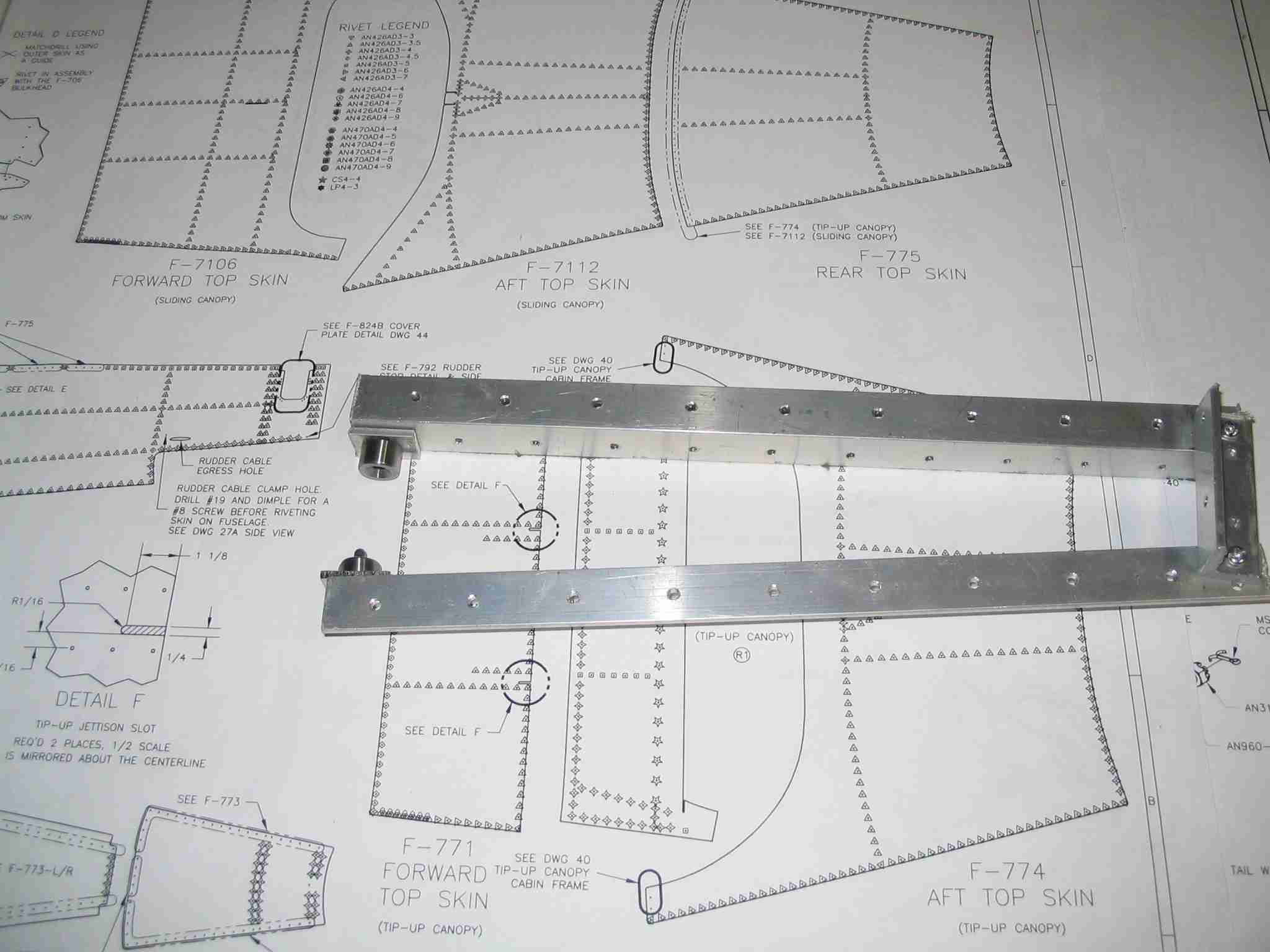
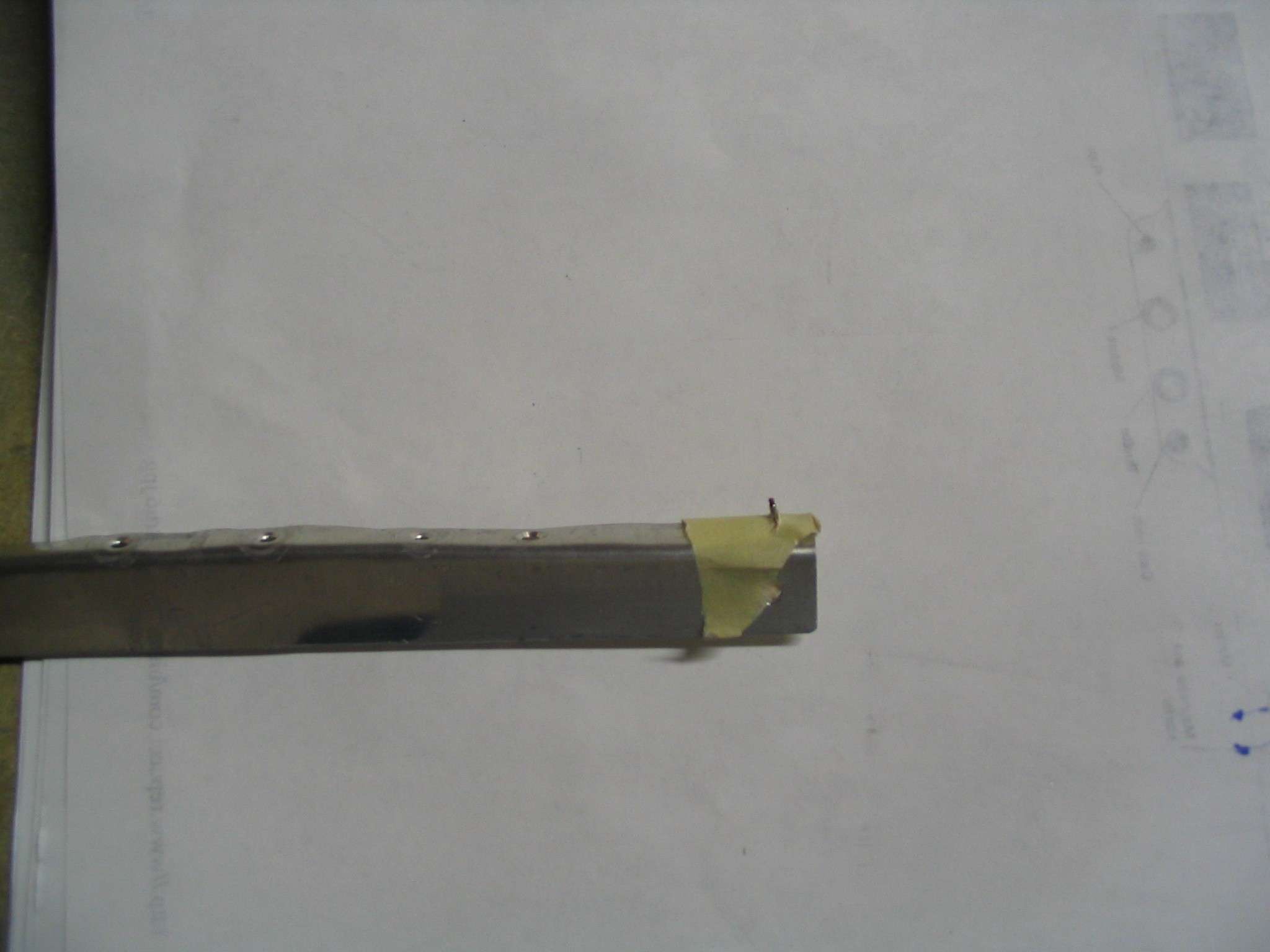
 F
Dummy me forgot to drill and dimple the holes in the aft side
skins where the rudder cable sheathing is held in place before
I riveted it all together. The solution was to take some
aluminum angle and make a long reach dimple press. I
will use a clamp or similar tool to squeeze the thing
together. Note the through depth. This will reach
over the "J" stringers and in a trial fit, looks like it will
work out fine. F
Dummy me forgot to drill and dimple the holes in the aft side
skins where the rudder cable sheathing is held in place before
I riveted it all together. The solution was to take some
aluminum angle and make a long reach dimple press. I
will use a clamp or similar tool to squeeze the thing
together. Note the through depth. This will reach
over the "J" stringers and in a trial fit, looks like it will
work out fine.
Back to top |
|
July 15, 2005 -
Knee/back/head pad
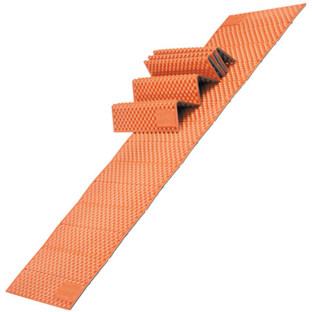
 E
This tip didn't even dawn on me until I went over to help out
a friend with his RV-9A. He had a problem at an airport
other than his home base so we both packed up the tools we
thought we would need and in doing so I grabbed an old foam
backpacker's mattress that I have been using in my shop.
Probably the best one going is the Z-Rest from Therm-a-Rest.
They cost $34.95 from
CAMPMOR.
I like this one because you can fold it up to fit the area you
are working in, such as the cockpit. E
This tip didn't even dawn on me until I went over to help out
a friend with his RV-9A. He had a problem at an airport
other than his home base so we both packed up the tools we
thought we would need and in doing so I grabbed an old foam
backpacker's mattress that I have been using in my shop.
Probably the best one going is the Z-Rest from Therm-a-Rest.
They cost $34.95 from
CAMPMOR.
I like this one because you can fold it up to fit the area you
are working in, such as the cockpit.
It is much easier the
knees to kneel on one of these than to kneel on concrete or
aluminum.
Back to top |
| |
|
July 15, 2005 -
Long reach scribe
Ok, if I didn't make so many darn mistakes I would be flying
by now. Then again, making mistakes allows me the
freedom to figure out creative solutions. This time I
didn't drill the main spar flange side caps earlier and I had
drilled one hole in the flange to hold the forward end of the
armrest in place. The problem I now had was how do I
match drill the hole from the outside of the cap and into the
existing hole without elongating it? Worse yet,
the hole was about a foot down the inside of the spar flange
cap.
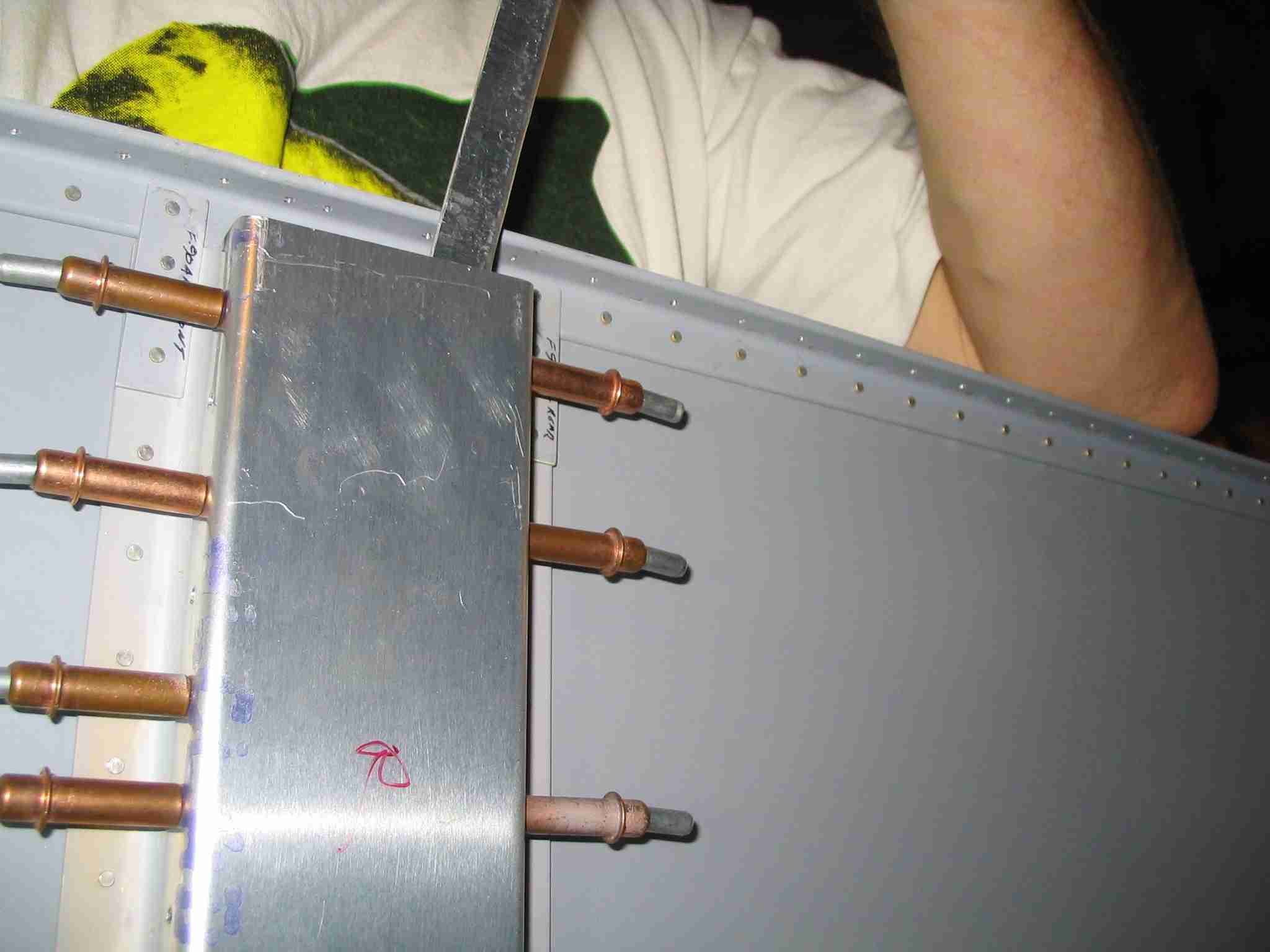
 F
What I did was take a long piece of scrap aluminum and bend a
flange along its length to give it some strength. Of
course it had to be thin enough to fit down the hole created
when you put the spar cap on. I then pulled the tip off
of a Sharpie and drilled a hole the size of the base of the
Sharpie tip in one end of my newly flanged scrap aluminum
strip. F
What I did was take a long piece of scrap aluminum and bend a
flange along its length to give it some strength. Of
course it had to be thin enough to fit down the hole created
when you put the spar cap on. I then pulled the tip off
of a Sharpie and drilled a hole the size of the base of the
Sharpie tip in one end of my newly flanged scrap aluminum
strip.
  F
The tip was then placed in the aluminum strip and taped in
place so it wouldn't fall out. The next thing to do was
reach down the spar flange with the "new tool" and mark the
hole on the spar flange cap from the inside. Once I
removed the cap the hole was clearly marked and was easy to
drill. F
The tip was then placed in the aluminum strip and taped in
place so it wouldn't fall out. The next thing to do was
reach down the spar flange with the "new tool" and mark the
hole on the spar flange cap from the inside. Once I
removed the cap the hole was clearly marked and was easy to
drill.
Back to top |
| |
|
July 17, 2005 -
Aircraft Grade Pooper
Scooper
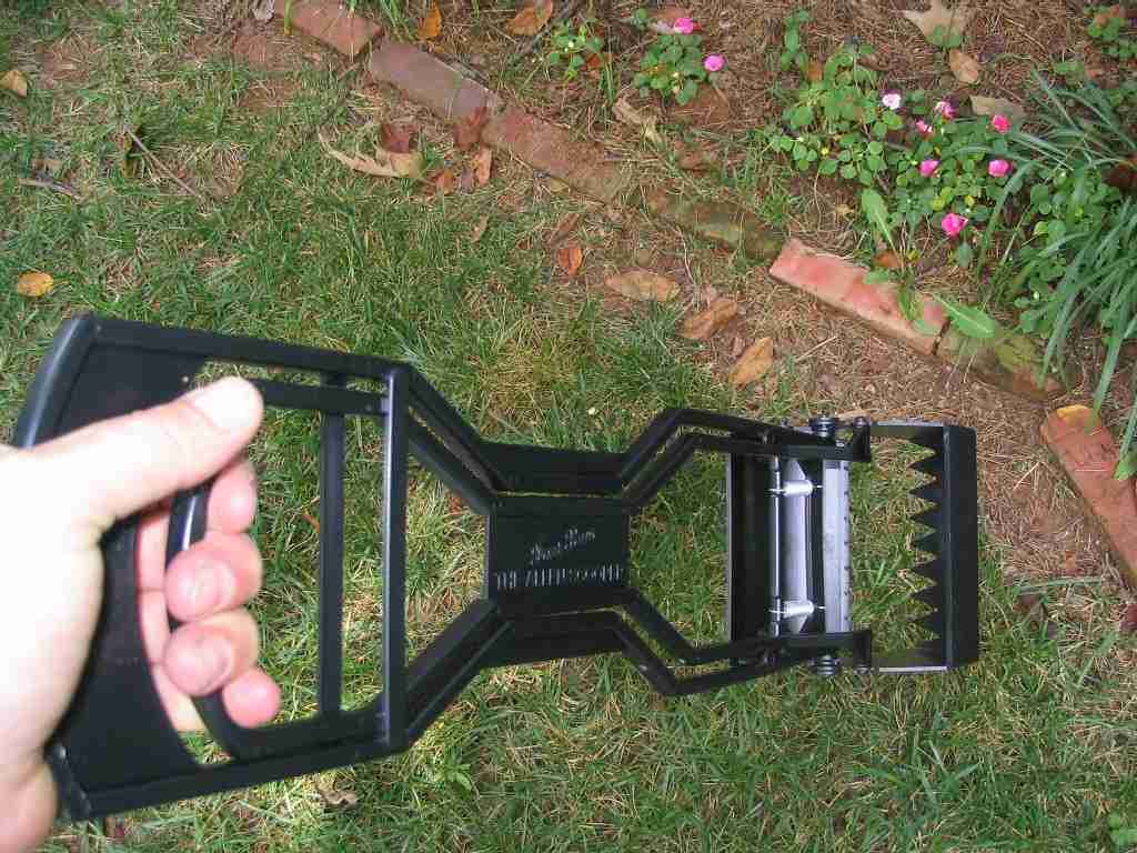
Well, it is
aircraft grade when you considered I used my newly acquired
metal fabricating skills to make it. The first picture
is the stock scooper. A good unit and one you can
operate single handed, which is a bonus when you are using
your other hand to hold back 51 lbs of Torque AKA the poop
producing Bull Dog puppy and need to fling the freshly scooped
poop into the woods.
 E
Here is the stock unit with the jaws held open, an action
shot, if you will. Not a bad design but the plastic
tends to break. One scoop lasted 10 months and its
replacement lasted one day. Thus the need for the
modification. E
Here is the stock unit with the jaws held open, an action
shot, if you will. Not a bad design but the plastic
tends to break. One scoop lasted 10 months and its
replacement lasted one day. Thus the need for the
modification.
 E
A quick trip to the Aviation section at Home Depot turned up
some U-channel pooper grade aluminum stock and pop rivets.
The rest, as they say, is history. E
A quick trip to the Aviation section at Home Depot turned up
some U-channel pooper grade aluminum stock and pop rivets.
The rest, as they say, is history.
Back to top |
| |
|
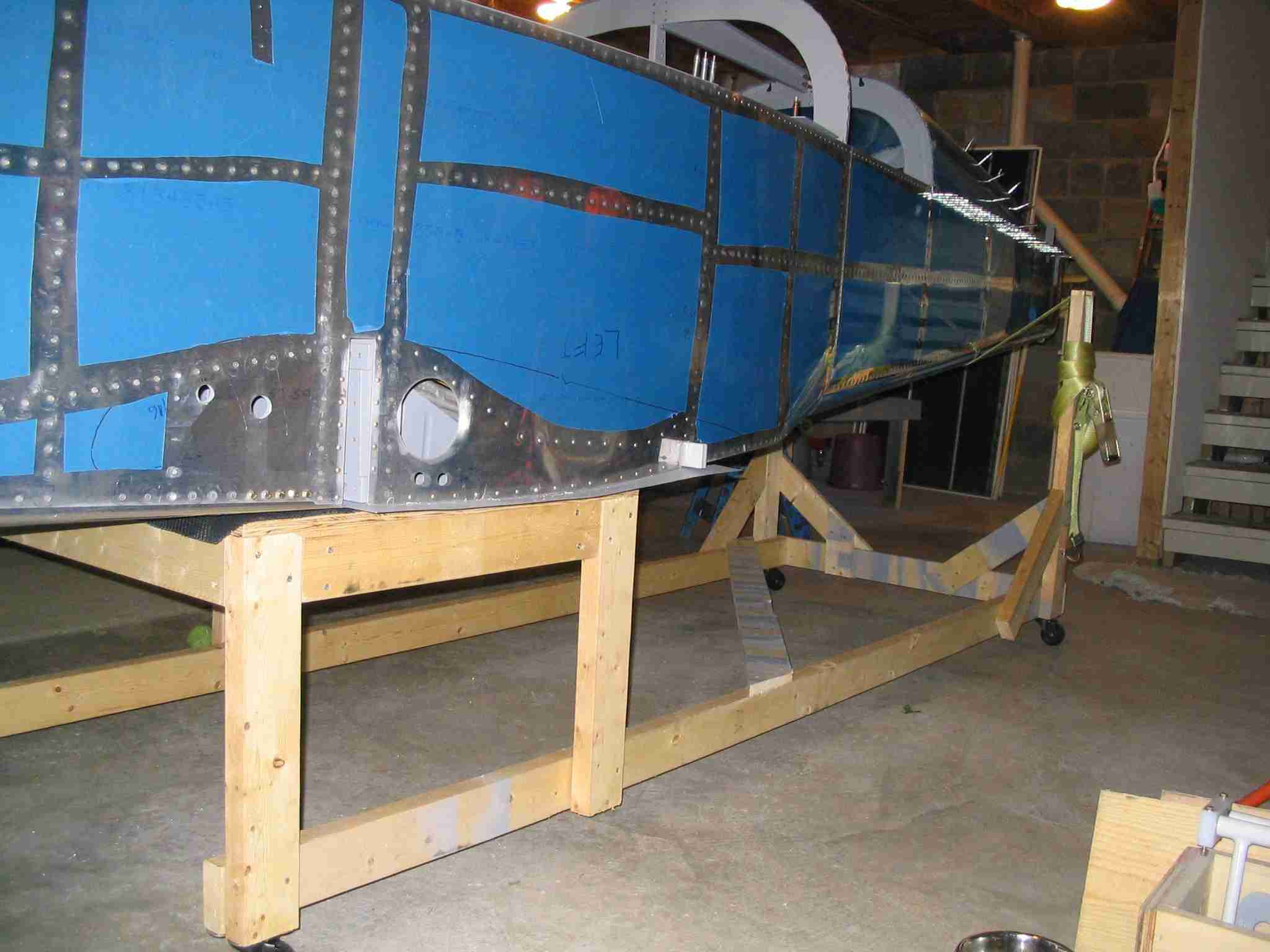
July 30, 2005 -
Roll Around Fuselage
Stand
With the
fuselage sitting up on sawhorses it was a bit too high to work
on comfortably. Since I hadn't drilled the firewall for
the engine mount it wasn't possible to attach rotisserie type
engine stand yet and I wanted to be able to climb in the
fuselage as I worked, be able to move the thing around the
shop, and raise and lower the tail as needed to level the
thing. The following three pictures are what I came up
with.
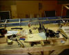
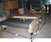
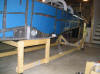 F This picture if of the
"table". It was made of some scrap 3/4" plywood and
2x4's I had laying around. The long horizontal 2x4's are
from the wing jig and run back to the tail cradle. The
entire thing is on wheels so it can be moved around the shop
as needed.
F This picture if of the
"table". It was made of some scrap 3/4" plywood and
2x4's I had laying around. The long horizontal 2x4's are
from the wing jig and run back to the tail cradle. The
entire thing is on wheels so it can be moved around the shop
as needed.
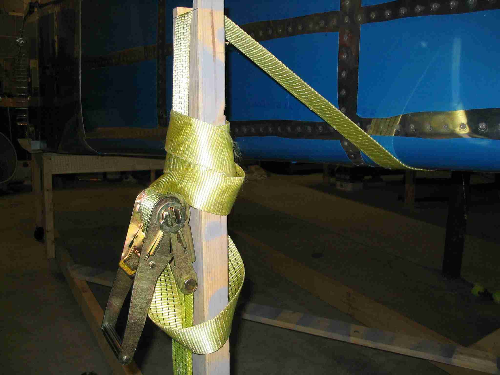
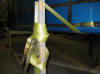 F
Because I'm lazy and figured I would never get the tail to sit
at the correct height I bought a 2" ratcheting tie down strap
to raise and lower the tail.
F
Because I'm lazy and figured I would never get the tail to sit
at the correct height I bought a 2" ratcheting tie down strap
to raise and lower the tail.
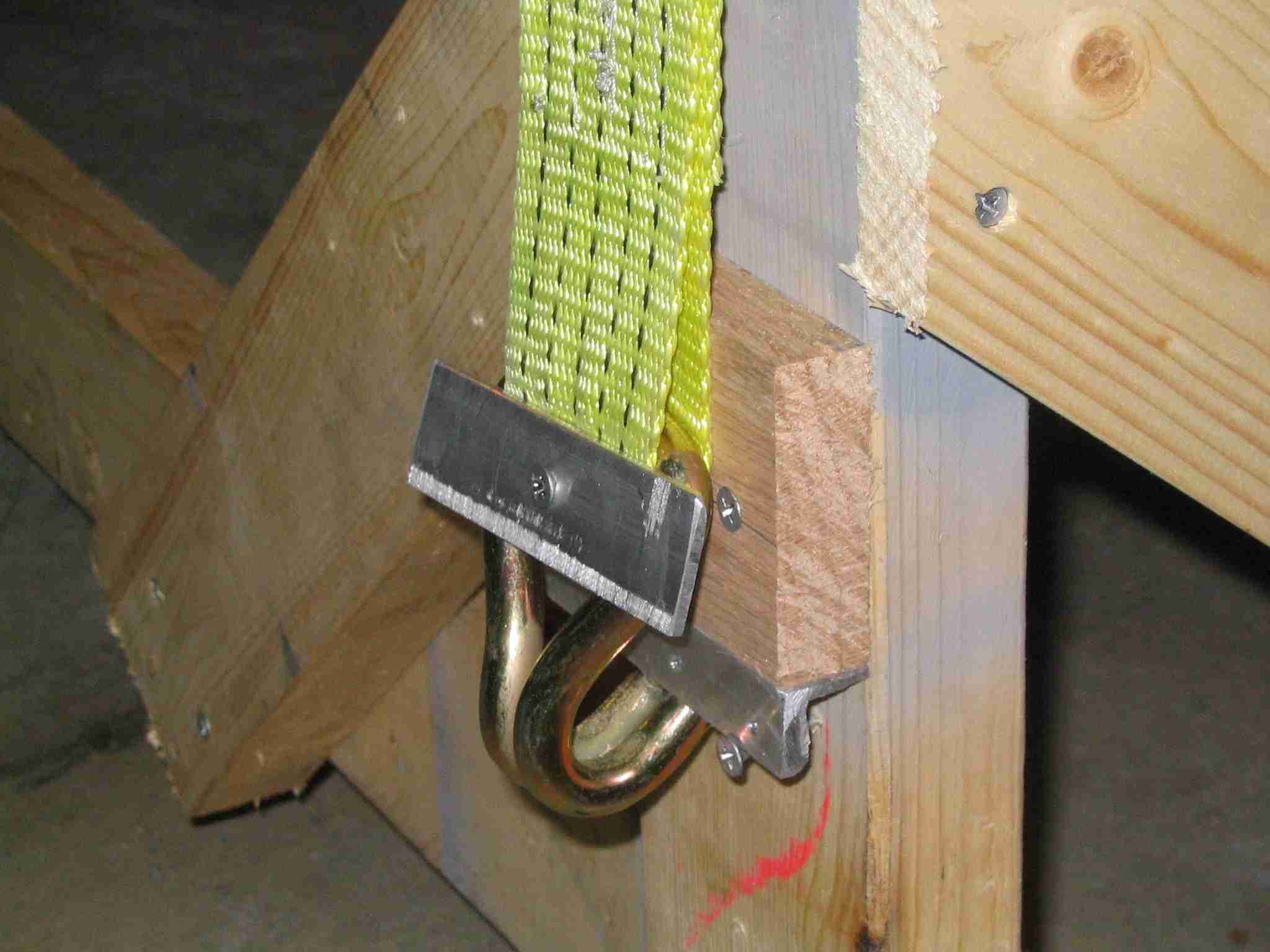
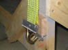 F
To keep the hooks from pulling out of the simple little
brackets I made for them I took a strip of aluminum and
screwed it through the hook eyelet. Note the bracing
used to keep the cradle from moving inward and forward.
It does move around a bit but I don't have to worry about it
falling like I did when it was supported by two sawhorses. F
To keep the hooks from pulling out of the simple little
brackets I made for them I took a strip of aluminum and
screwed it through the hook eyelet. Note the bracing
used to keep the cradle from moving inward and forward.
It does move around a bit but I don't have to worry about it
falling like I did when it was supported by two sawhorses.
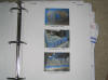
 F
A fellow builder asked for the dimensions of the stand and
since I just put the -9 on its gear taking a 1/2 decent
picture of it was easy enough to do. The height of the
table does not include the full castering wheels. The
black and white stuff on the table are rubber tool box liner
to keep from scratching the skins. If you go this route, get
some rubber furniture cups to put under the wheels to keep it
from rolling around your shop. F
A fellow builder asked for the dimensions of the stand and
since I just put the -9 on its gear taking a 1/2 decent
picture of it was easy enough to do. The height of the
table does not include the full castering wheels. The
black and white stuff on the table are rubber tool box liner
to keep from scratching the skins. If you go this route, get
some rubber furniture cups to put under the wheels to keep it
from rolling around your shop.
Back to top |
| |
|
September 25, 2005 -
How to
accurately measure the tail and wings
While fitting the
horizontal stabilizer you will need to measure from a common
point on both tips to a common point on the fuselage.
Using a string seams like the natural choice but that can and
will stretch. I have heard of people using safety wire,
which sounds good but there is a better way.
Drill a #40 hole in
the center of your tape measure at the 3" mark. Cleco
the tap measure to a hole in the HS and then measure to a
common point on the fuselage. This works better than the
string method because you can pull the tape tight to get an
accurate measure.
Back to top |
| |
|
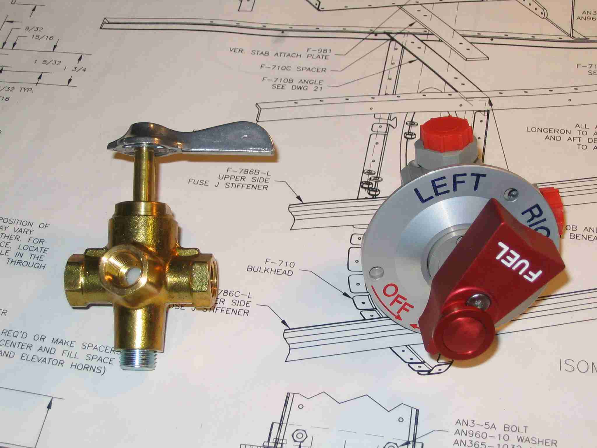
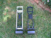
September 25, 2005 - Fuel Valves
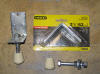
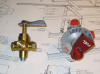 F
The valve on the left is from Van's, the valve on the right is
from
Andair. It is obvious that quality of the Andair
valve exceeds that of the one Van's includes with the kit.
Originally I had planed on using the Van's valve as the other
is rather expensive. Then I spoke to gentleman who had
built two RV's and out of the blue he asked me which valve I
was using. His experience with the Van's valve was
enough to convince me to buy the Andair unit. His
comments were along the lines of, "The Van's valve will fail
after 100 hours. You can replace it with another Van's
valve every 100 hours or re-plumb your plane to accept the
Andiar valve, which is a task on a completed plane." He
strongly encouraged me to buy and install the Andair valve
now, while my RV was under construction. When I returned
home I pulled the Van's valve out of the bag, looked at it,
played with it, and then ordered the Andair. F
The valve on the left is from Van's, the valve on the right is
from
Andair. It is obvious that quality of the Andair
valve exceeds that of the one Van's includes with the kit.
Originally I had planed on using the Van's valve as the other
is rather expensive. Then I spoke to gentleman who had
built two RV's and out of the blue he asked me which valve I
was using. His experience with the Van's valve was
enough to convince me to buy the Andair unit. His
comments were along the lines of, "The Van's valve will fail
after 100 hours. You can replace it with another Van's
valve every 100 hours or re-plumb your plane to accept the
Andiar valve, which is a task on a completed plane." He
strongly encouraged me to buy and install the Andair valve
now, while my RV was under construction. When I returned
home I pulled the Van's valve out of the bag, looked at it,
played with it, and then ordered the Andair.
Back to top |
| |
|
October 9, 2005 -
Reamers
There are a good number of parts that receive AN3 & AN4 bolts.
Some of these parts are pre drilled and some are not.
The problem with using a drill bit to size a hole is that they
will give you a triangular hole which is not very good if the
bolt you are going to put through it is critical. One
way to solve this problem is to drill the hole undersized and
then use a reamer to enlarge to the proper size. One
thing to consider is that reamers will not straighten a
crooked hole, they will only size it properly while following
the existing hole.
The three reamer
sizes I have used to date are 1/4", 5/16", & 9/16". If I
find I need another size, I will update this page.
Back to top |
| |
|
January 10, 2006 -
Serial Numbers
Throughout the
building of your aircraft you will install a number of items
that have serial numbers. I strongly suggest you create
a spreadsheet to track all of these. It would be a major
pain in the butt to have to pull an instrument out of your
panel to check a serial number IF an AD is issued against them
only to find out your instrument was not included in the AD.
Back to top |
| |
|
March 26, 2006 -
Instrument Wire Runs
A fellow RV builder
recommended installing plate nuts (K1000-8) on the bottom of
the ribs that support the instrument panel. These will
facilitate using Adel clamps to hold wires running back and
forth behind the panel and forward to the fire wall.
Each rib has five plate nuts. The first is one inch
behind the instrument panel, the second is one inch in front
of the sub panel, the third is one inch behind the sub panel,
the fourth is six inches further forward, and the fourth is
one inch aft of the fire wall which also works out to be six
inches forward of the fourth plate nut. This may be over
kill but it will sure make installing all of those wires
easier.
Back to top |
| |
|
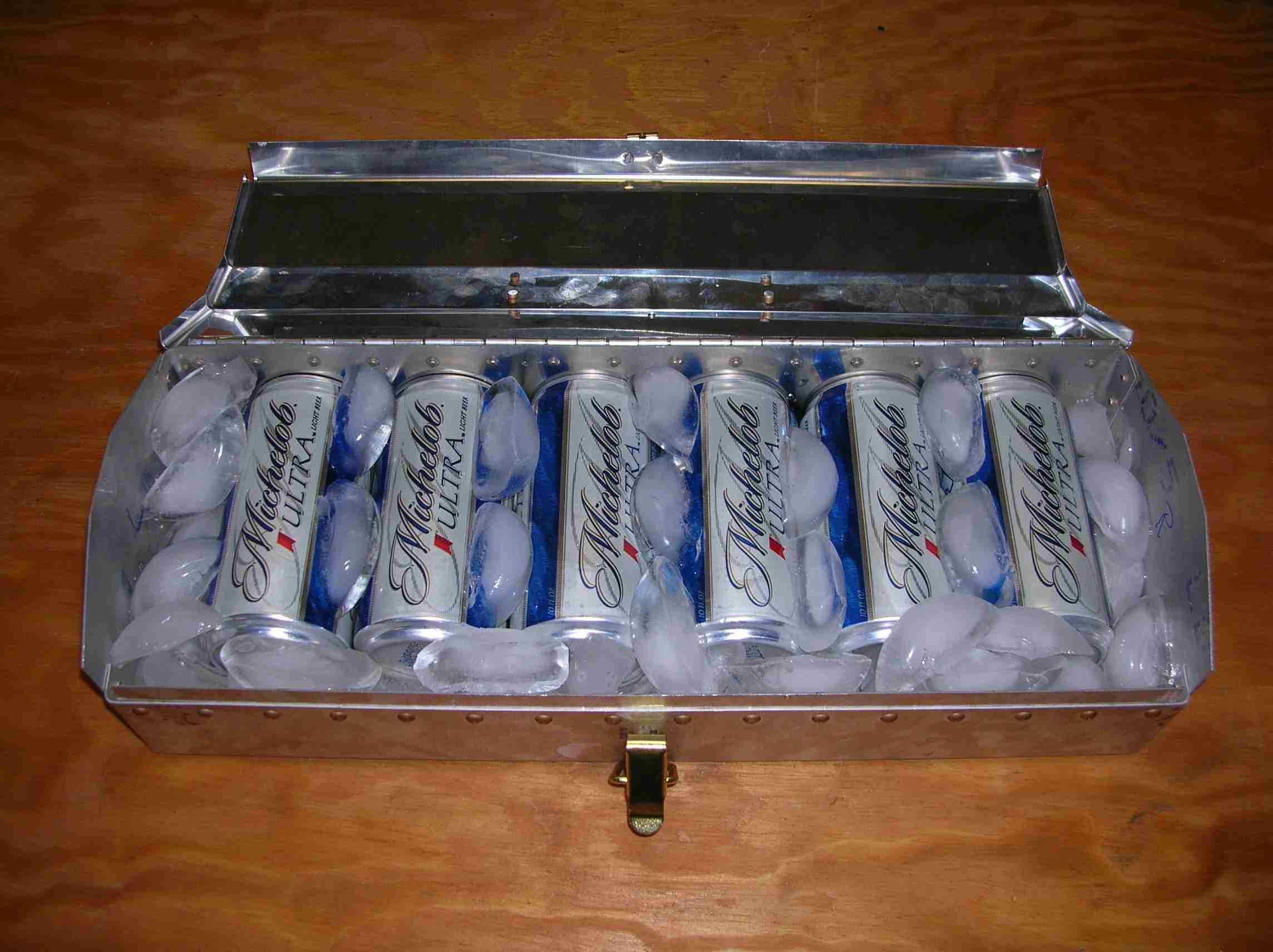
April 22, 2006 -
Van's Toolbox
On April 22nd. EAA
309 held a workshop for prospective builders. Although
the class was not centered on building RV's, Van's was kind
enough to contribute a number of their pre-punched toolbox
kits for us to use. After the class was over, Bill
Wilson figured out how Van's determined the size of the box.
Back to top |
| |
|
June 15, 2006 -
Drilling out flush
and Pop Rivets
My
steps for drilling out flush rivets.
1.
Center punch the rivet. There should be a dimple there but
not always. Besides, it doesn't hurt to make the dimple
bigger.
2.
Start drilling.
3.
Remove the drill and look at the hole, if it is off center,
"push" it over with the drill.
4.
Once the hole is about as deep as the dimple, take an old
drill bit of the same size, turn it around and put the shaft
in the hole. Bend the drill bit over and the rivet head
should pop off. Hint, use an old drill bit because you can
bend #40 bit very easily. (Same goes for setting the drill
down, be careful not to set it down bit first. If you do, you
will bend the bit.)
5.
Drill the remainder of the rivet out.
By
the time you get to the fuselage you should be able to drill
out an entire wing panel w/o buggering up any holes.
Pop or Pull rivets:
1.
Find a nail the size of the hole in the rivet.
2. Grind off the point.
3.
Put the modified nail in the hole and hit it lightly with a
hammer. (This will drive out the "pin". If you don’t drive
the “pin” out the drill bit will wonder off center when it
hits it as it is harder than the aluminum rivet.)
4.
Drill out the rivet using the appropriate drill bit. (If the
rivet starts to spin, try a little JB weld on it to keep it
from moving. Just a little, because you will have to remove
the rivet head later.)
Back to top |
| |
|
August 18, 2006 -
POH & Condition
Inspection
Note: These documents
are a DRAFT. At the time I made them available my RV-9
had not been weighed, thus you will note some discrepancies in
the W&B section. If you elect to use these documents,
edit them to match the numbers for your airframe.
 E
Before your first flight you will be
required to write up a POH (Pilot Operating Handbook).
Here is a DRAFT of the POH I have assembled from various
sources. This document is based on the RV-9 I am
building and no other aircraft. All the numbers are in
MPH, not knots. I would like to thank the person who
came up with the original format but I do not know who
that is. E
Before your first flight you will be
required to write up a POH (Pilot Operating Handbook).
Here is a DRAFT of the POH I have assembled from various
sources. This document is based on the RV-9 I am
building and no other aircraft. All the numbers are in
MPH, not knots. I would like to thank the person who
came up with the original format but I do not know who
that is.
 E
A year after the first flight a
condition inspection (AKA Annual) must be performed on your
airplane. The attached document is a DRAFT of the items
that will be checked during the inspection of N941WR.
The attached list is specific to this aircraft and the
equipment installed, ignition system, etc. and no other. E
A year after the first flight a
condition inspection (AKA Annual) must be performed on your
airplane. The attached document is a DRAFT of the items
that will be checked during the inspection of N941WR.
The attached list is specific to this aircraft and the
equipment installed, ignition system, etc. and no other.
Back to top |
| |
|
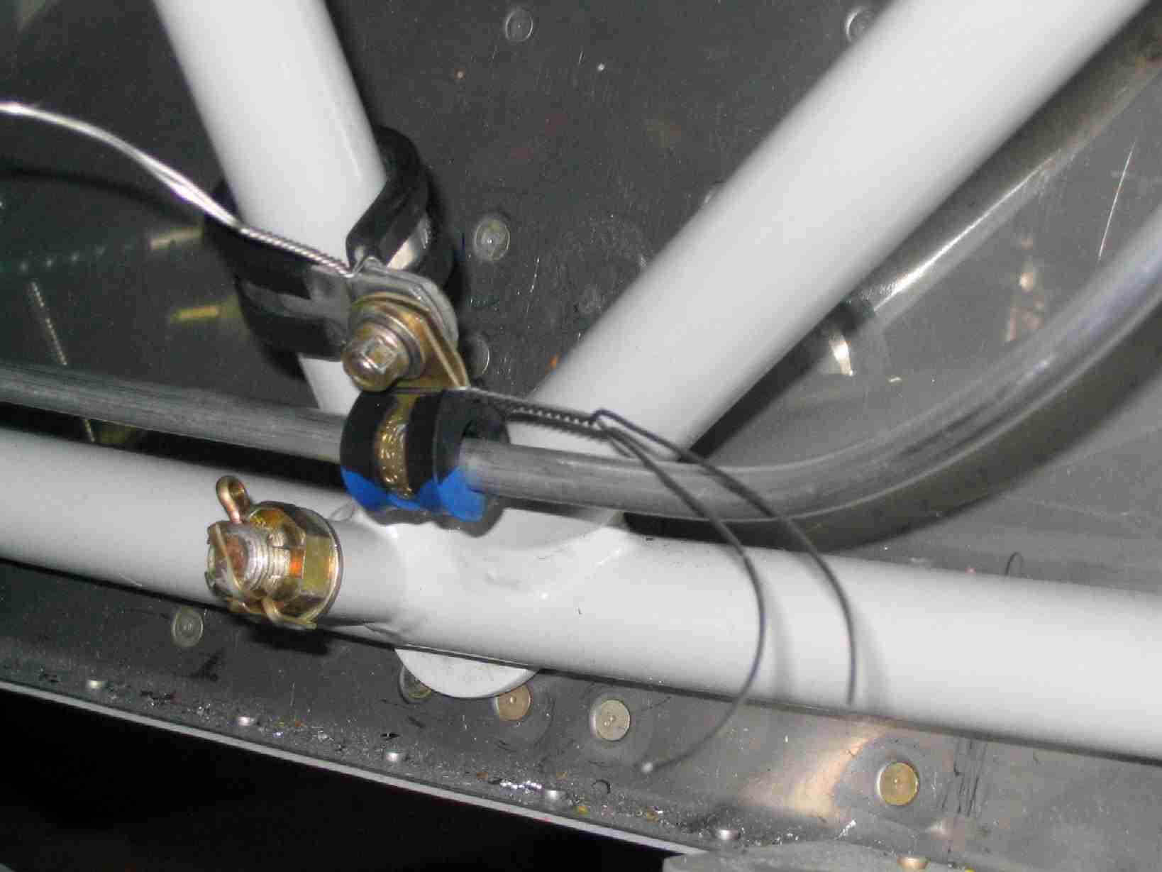
October 14, 2006 -
Installing Adel Clamps
 F
If you haven't installed an Adel clamp, you are in for one of
the home builder's greatest challenges. That is, unless
you follow this simple little tip. I discovered this in
a moment of brilliance. I suspect others are doing this
but I had never heard of it before and it worked out great.
Use some safety wire to draw the Adel clamp closed, making it
a snap to install the bolt, washer and nut. Just
remember to remove the wire before tightening the nut. F
If you haven't installed an Adel clamp, you are in for one of
the home builder's greatest challenges. That is, unless
you follow this simple little tip. I discovered this in
a moment of brilliance. I suspect others are doing this
but I had never heard of it before and it worked out great.
Use some safety wire to draw the Adel clamp closed, making it
a snap to install the bolt, washer and nut. Just
remember to remove the wire before tightening the nut.
I sure wish I
had thought of this sooner.
Back to top |
| |
|
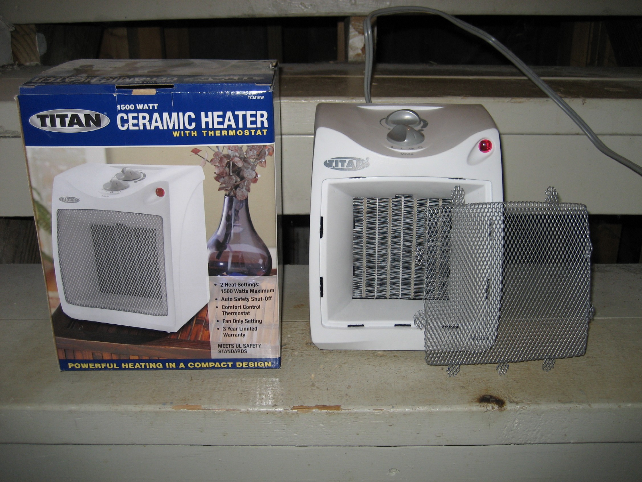
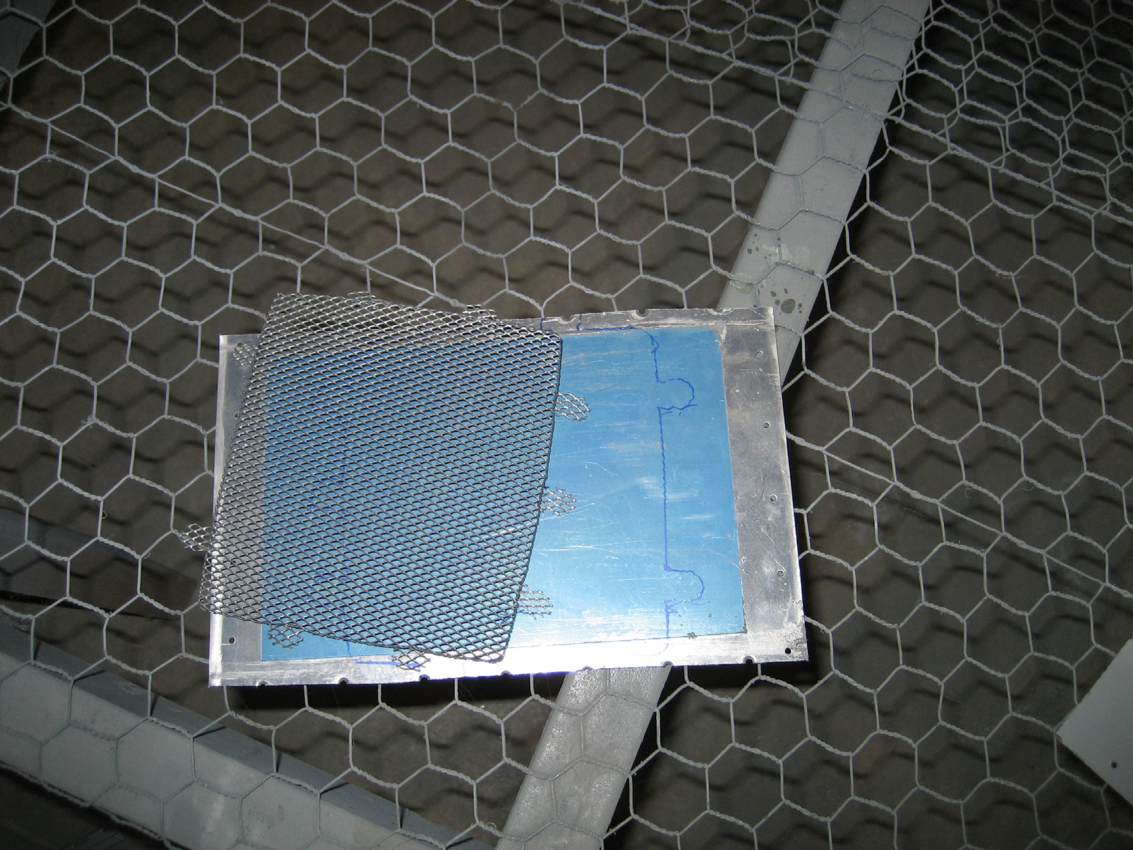
January 16, 2009 -
Inexpensive Engine
Pre-Heater
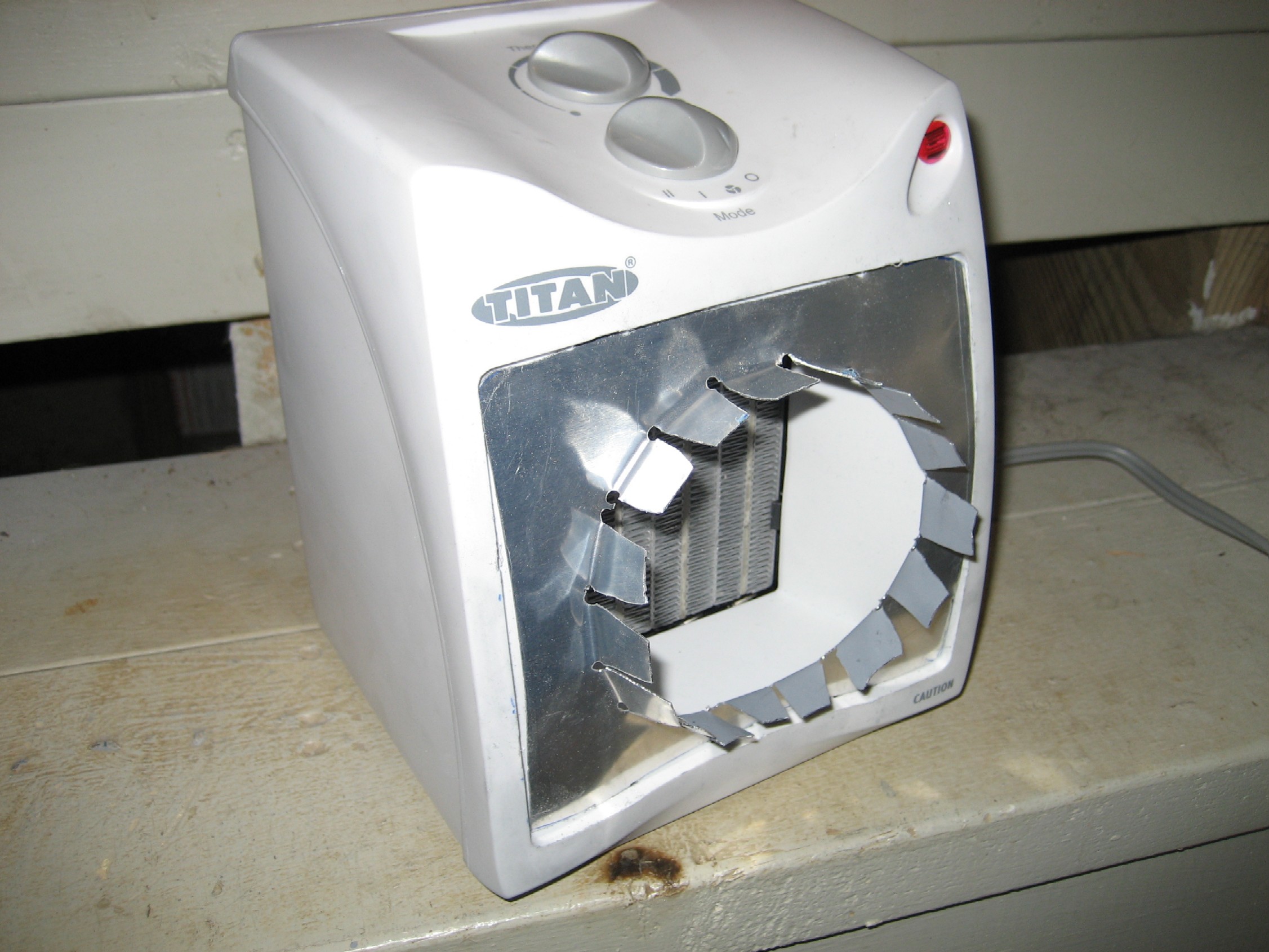
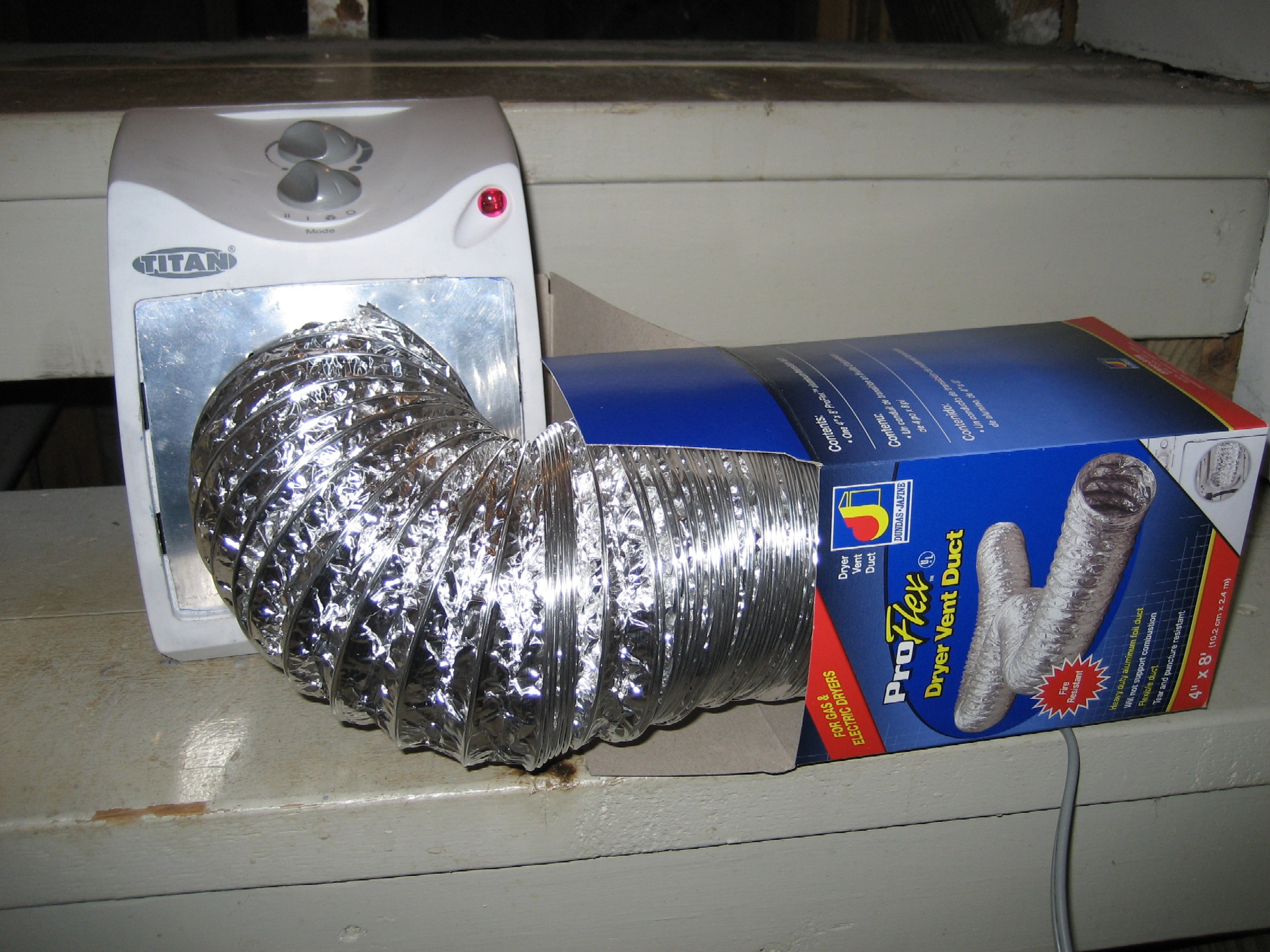
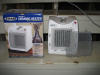    E
It came time for me to create a simple and cheap engine
pre-heater. While this isn't an original idea, I just
simply worked with the items I had laying around. An
inexpensive ceramic heater ($21) from Wal-Mart, some scrap aluminum
(In this case it was a damaged elevator skin left over from my
initial build.), and a dryer vent hose ($10 ) from the aviation
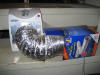
isle at Lowe's. E
It came time for me to create a simple and cheap engine
pre-heater. While this isn't an original idea, I just
simply worked with the items I had laying around. An
inexpensive ceramic heater ($21) from Wal-Mart, some scrap aluminum
(In this case it was a damaged elevator skin left over from my
initial build.), and a dryer vent hose ($10 ) from the aviation
isle at Lowe's.
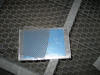
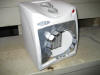
After removing the screen from the heater, it was used as a
template to trace out the shape, including the tabs on the
scrap aluminum. That piece was then cut to fit the
opening in the heater. A four inch circle was cut out,
including tabs to attach the dryer hose. To secure
everything, aluminum heat duct tape will be used.
It
can't much simpler than that.
Back to top |
| |
|
January 22, 2009 -
Firewall mounted oil
cooler
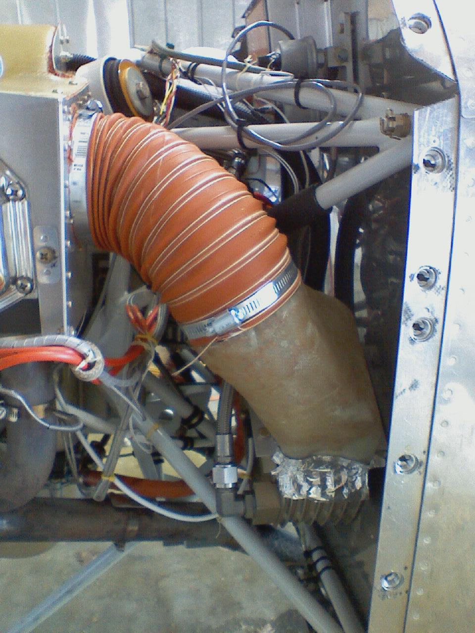
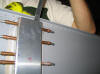
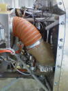 F
The night before we were scheduled to depart for SnF 08 a
friend was struggling with high oil temps. After doing
much research he felt the solution was to install a 4" SCAT
tube from the baffle down to the oil cooler. He had
purchased a 4" flange which he was going to rivet to the
baffle, after enlarging the hole but the big question was,
"How are we going to attach that hose to the oil cooler?"
The solution was simple, fiberglass, clay, and Styrofoam.
Two rectangular pieces of blue Dow Styrofoam were cut to match
the oil cooler, which was bolted to the firewall. Clay
was then used to form the transition from the Styrofoam to the
hose. As the clay was built up and around the
engine mount, the 4" flange, which was not yet riveted in
place, was pressed into the clay and the inside filled with
even more clay. Any clay on the outside of the flange
was removed and the transition was smoothed over. (This
was done to form a perfect 4" circle for the SCAT tubing.)
Once it looked like everything would fit, the clay and
Styrofoam mold was taken home and three layers of fiberglass
was laid over it. The next morning it was put in place
and the angle aluminum braces were match drilled to it and
riveted in place using pull-rivets. The hole in the
baffle was enlarge, the 4" flange riveted in place, and the
SCAT tube installed. Problem solved. F
The night before we were scheduled to depart for SnF 08 a
friend was struggling with high oil temps. After doing
much research he felt the solution was to install a 4" SCAT
tube from the baffle down to the oil cooler. He had
purchased a 4" flange which he was going to rivet to the
baffle, after enlarging the hole but the big question was,
"How are we going to attach that hose to the oil cooler?"
The solution was simple, fiberglass, clay, and Styrofoam.
Two rectangular pieces of blue Dow Styrofoam were cut to match
the oil cooler, which was bolted to the firewall. Clay
was then used to form the transition from the Styrofoam to the
hose. As the clay was built up and around the
engine mount, the 4" flange, which was not yet riveted in
place, was pressed into the clay and the inside filled with
even more clay. Any clay on the outside of the flange
was removed and the transition was smoothed over. (This
was done to form a perfect 4" circle for the SCAT tubing.)
Once it looked like everything would fit, the clay and
Styrofoam mold was taken home and three layers of fiberglass
was laid over it. The next morning it was put in place
and the angle aluminum braces were match drilled to it and
riveted in place using pull-rivets. The hole in the
baffle was enlarge, the 4" flange riveted in place, and the
SCAT tube installed. Problem solved.
Back to top |
| |
|
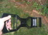
June 18, 2009 -
Ratchet Strap Tie Downs
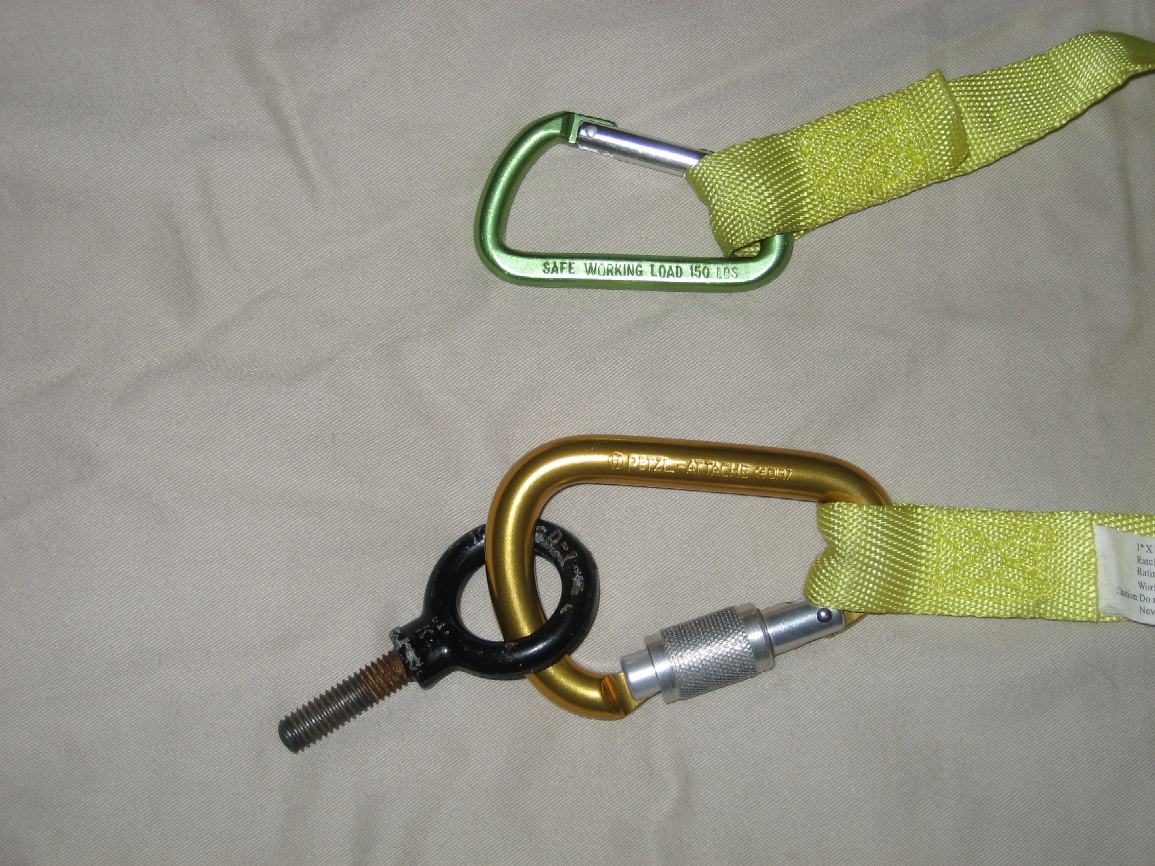
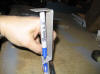
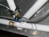
 E
A discussion on the VAF Forums raised a concern I have always
had regarding the use of ratchet straps as tie downs.
The issue I had was that to keep the hooks in place, you
really need to ratchet the plane down to the ground.
Even then, a good wind might bounce it enough to take the
hooks off the tie down ring. Two seconds with a
hacksaw had the hooks removed and a carabiner in its place.
Note in the picture I have a both a Petzl climber's beaner and
a cheap gear beaner. Use climber carabiners, not the
cheap ones you can buy at any hardware store. The cheap
ones I have are good for 150 lbs, which is better than the 40
lbs I usually see them stamped with. The Petzel is rated
at 24 kilonewtons with the wheel closed. More than
strong enough to hold my plane in place. E
A discussion on the VAF Forums raised a concern I have always
had regarding the use of ratchet straps as tie downs.
The issue I had was that to keep the hooks in place, you
really need to ratchet the plane down to the ground.
Even then, a good wind might bounce it enough to take the
hooks off the tie down ring. Two seconds with a
hacksaw had the hooks removed and a carabiner in its place.
Note in the picture I have a both a Petzl climber's beaner and
a cheap gear beaner. Use climber carabiners, not the
cheap ones you can buy at any hardware store. The cheap
ones I have are good for 150 lbs, which is better than the 40
lbs I usually see them stamped with. The Petzel is rated
at 24 kilonewtons with the wheel closed. More than
strong enough to hold my plane in place.
Back to top |
| |
|