|
Dynon Autopilot Installation notes, comments,
thoughts, and operation
Caution - Man running (with) power tools
| Prior to release (sale) of their
autopilot, Dynon Avionics put together a group of volunteers to the
autopilot in various airplanes. This was done because they
recognized that different planes have different flying qualities, thus
different demands from their autopilot.
The following is
from
Dynon's web site:
Test Program Update
Dynon has been working with a small fleet of testers on the flight
dynamics and performance qualities of the Autopilot for a few months now.
So far, the Dynon Autopilot is flying a diverse set of aircraft, including
examples of the RV-4, RV-6, RV-7, RV-8, RV-9, Glasair Sportsman 2+2, Sonex,
SeaRay, BD-4, and more. People familiar with these aircraft will recognize
that this represents a fairly wide range of stability profiles and
performance characteristics. As we move forward, we will continue to add
experience in different aircraft.
Needless to say, the diversity of aircraft
involved gave them a good idea of what to expect once the autopilots were
installed in customer's airplanes.
The following pictures and comments are mine
alone and in no way should be construed as the final say on the
installation of any autopilot/airplane combination. If you have
questions regarding your installation, I highly recommend you contact the
experts at Dynon and check the
Dynon Support Forum. |
| |
| My first comment to anyone who is
building is, if you think you may ever want to install an autopilot at
some point in the future, install the brackets now and run the required
wires while you are building. This will make life easier for you
later on. Obviously it is possible to install the brackets, wires,
and servos in a flying airplane, as I did, but it would have been easier
to do it had I pre-installed the brackets and wires during construction.
 E
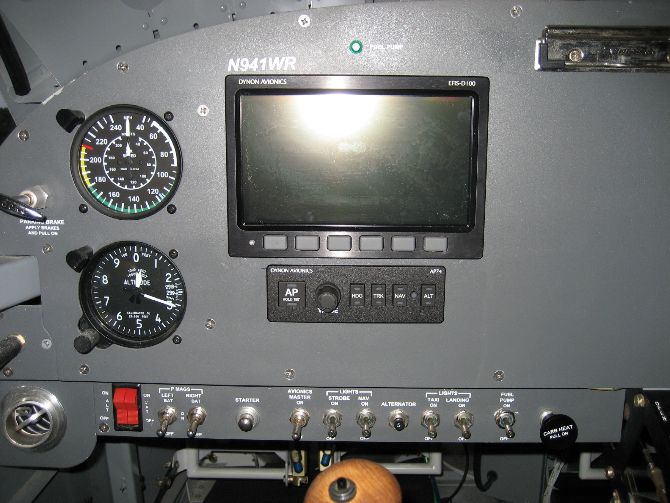
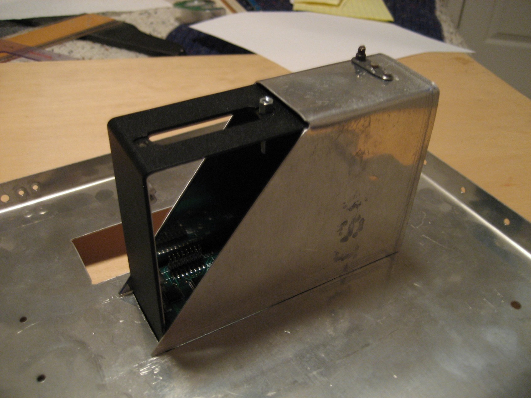
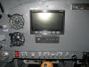
Installing the AP74 was easy enough. Cut a rectangular hole in the
panel and slide the thing in place. Only one problem, I didn't like
the standard Dynon retention bracket because it required drilling holes in
my finished panel, countersinking for flush rivets, and finally riveting
it in place. This would damage the panel and I didn't want to have
pull the panel out to refinish it. E
Installing the AP74 was easy enough. Cut a rectangular hole in the
panel and slide the thing in place. Only one problem, I didn't like
the standard Dynon retention bracket because it required drilling holes in
my finished panel, countersinking for flush rivets, and finally riveting
it in place. This would damage the panel and I didn't want to have
pull the panel out to refinish it. |
| |
|
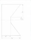   F
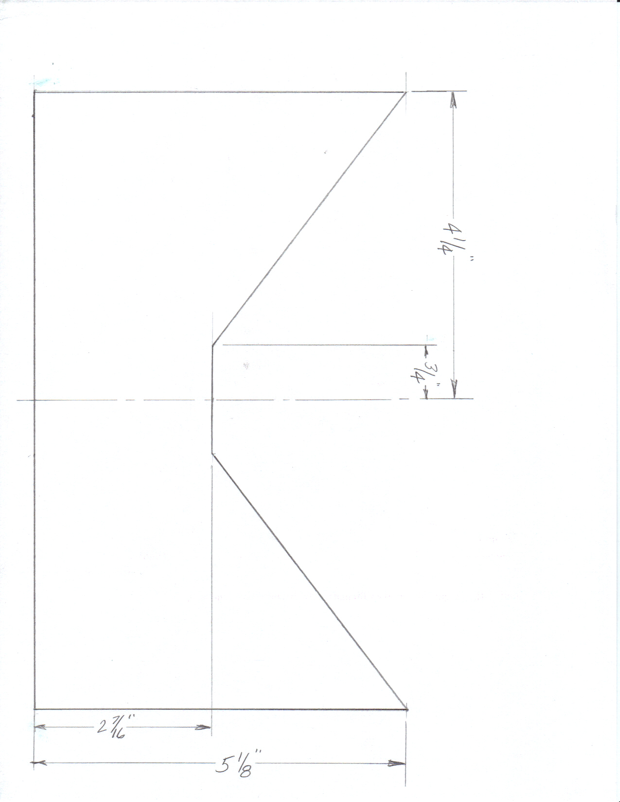
Thus I developed this retention bracket and it is my understanding Dynion
is going to put a similar unit into production. Should you elect to
copy my diagram, note that the retention screw in the AP76 may be in a
different place, thus you may have to modify this when upgrading.
Either way, it sure beats drilling out rivets in your panel for the
upgrade. F
Thus I developed this retention bracket and it is my understanding Dynion
is going to put a similar unit into production. Should you elect to
copy my diagram, note that the retention screw in the AP76 may be in a
different place, thus you may have to modify this when upgrading.
Either way, it sure beats drilling out rivets in your panel for the
upgrade.
Note that the first two pictures
show the AP74 being installed in scrap piece of aluminum and not in my
actual panel. The good news is the retention bracket worked great on
the actual panel. |
| |
|
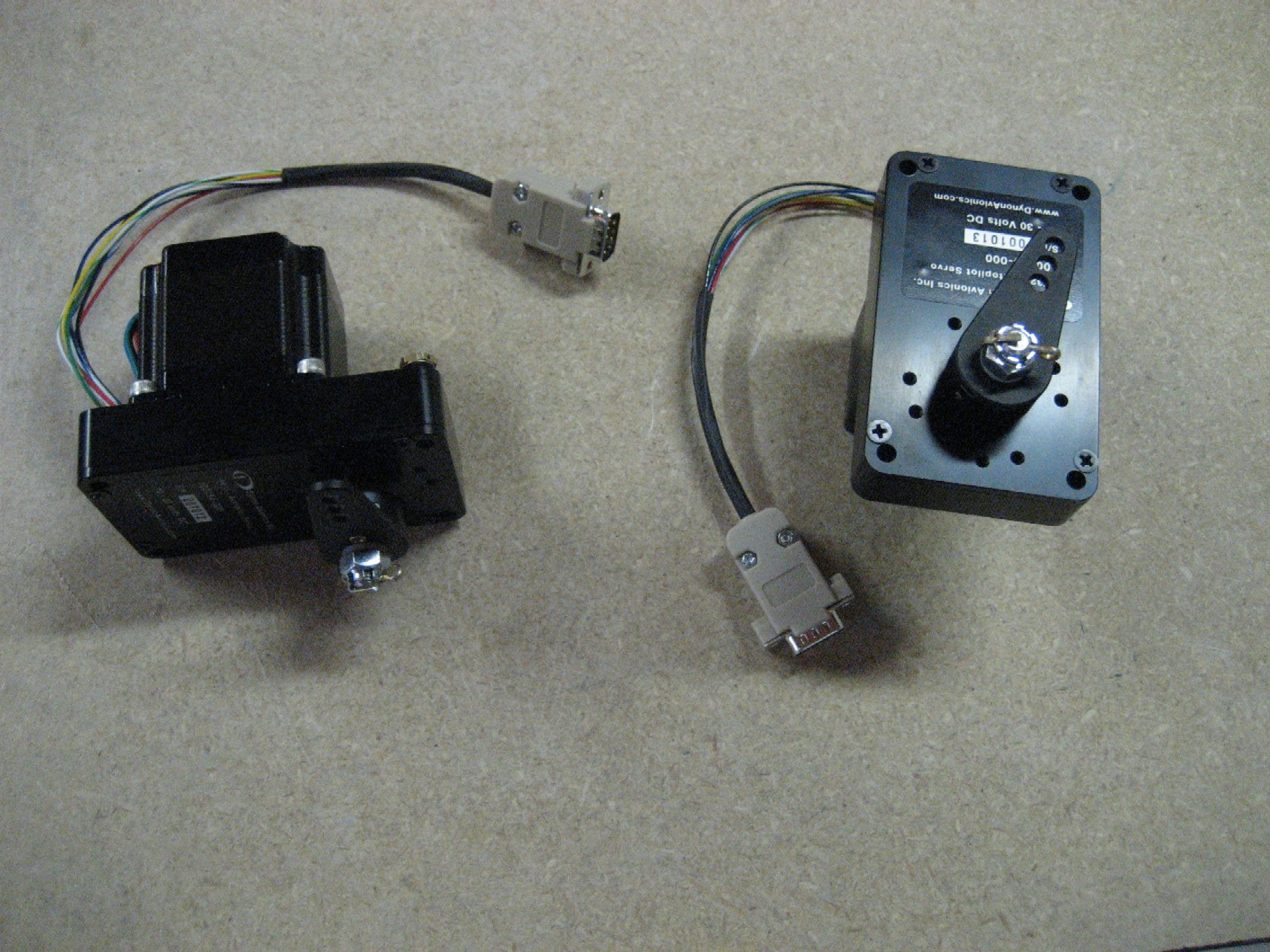
Servo Installation:
E
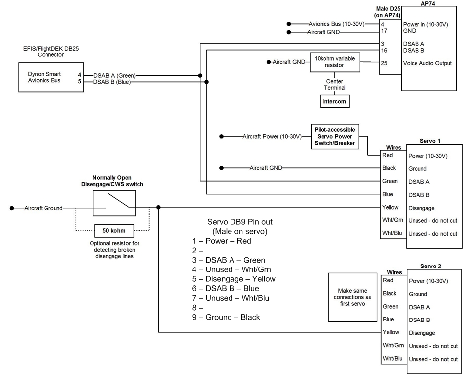
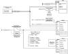
To
make future maintenance easier, I added DB9 connectors to both servos.
This diagram includes the pin-out I used on the connector. Verify
this diagram with your installation documentation from Dynon. The
schematic shown was taken from a pre-production document and may not be
accurate.
Servo DB9 Pin out
(Male on servo)
1 – Power – Red
2 –
3 – DSAB A – Green
4 – Unused – Wht/Grn
5 – Disengage – Yellow
6 – DSAB B – Blue
7 – Unused – Wht/Blu
8 –
9 – Ground – Black
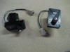 F
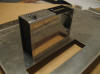
Here is a picture of both servos with the DB9 connectors installed.
Should these ever go in for maintenance or replacement, I suspect I'll be
installing a new DB9 connector. Note the shrink tubing used on the
wires. F
Here is a picture of both servos with the DB9 connectors installed.
Should these ever go in for maintenance or replacement, I suspect I'll be
installing a new DB9 connector. Note the shrink tubing used on the
wires.
|
| |
|
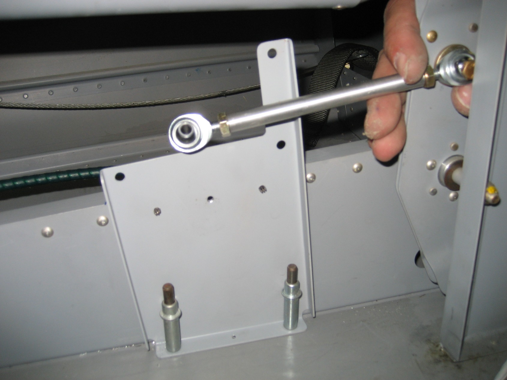
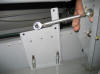 E
As mentioned earlier, installing the pitch servo
is a challenge on a completed plane, mostly because you are working on
your hands and knees. That and I elected to drill and rivet through
the floor of my plane. E
As mentioned earlier, installing the pitch servo
is a challenge on a completed plane, mostly because you are working on
your hands and knees. That and I elected to drill and rivet through
the floor of my plane.
|
| |
|
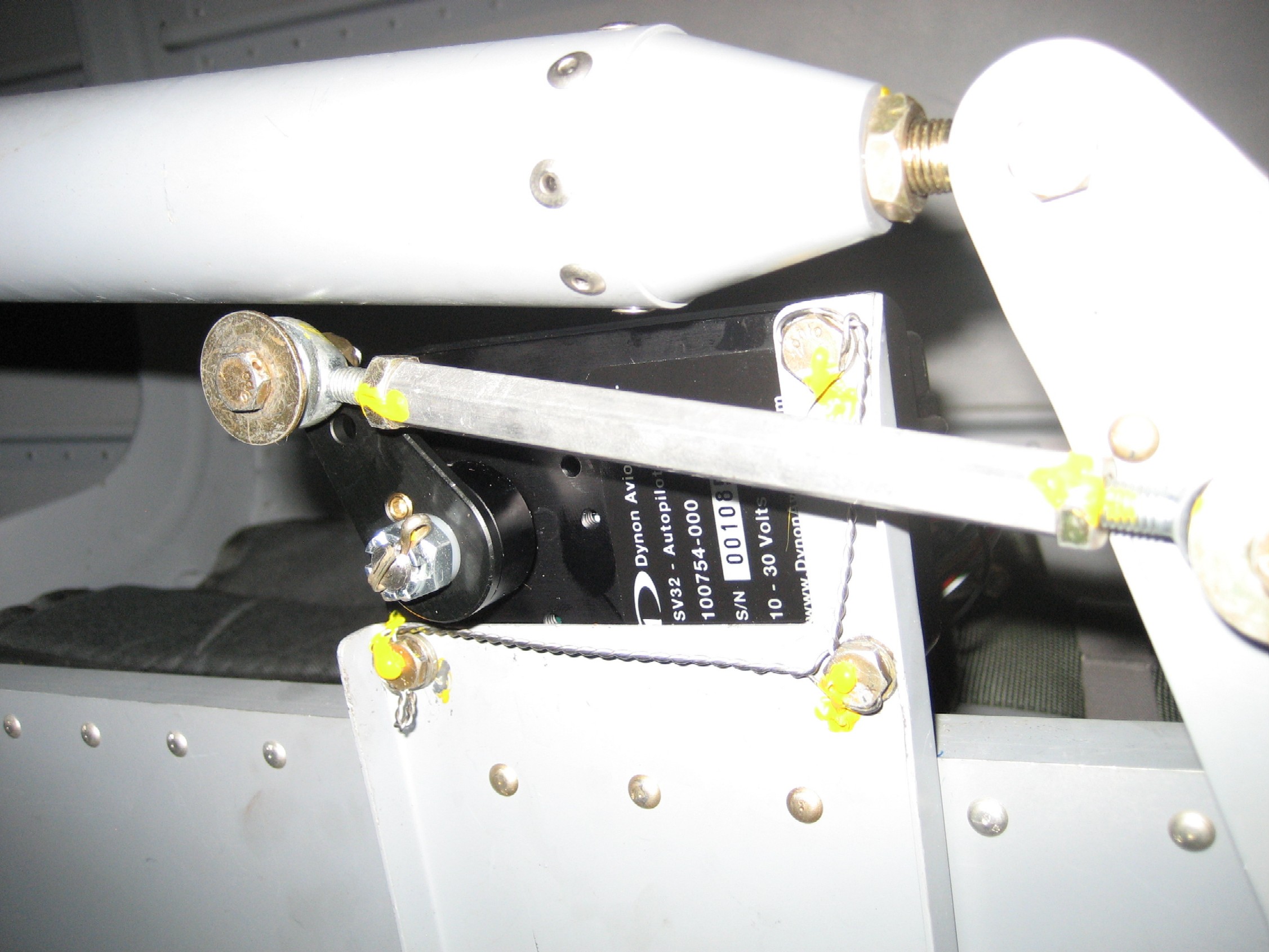
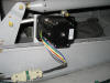
 F
Installing the pitch servo was easy enough and
there was no interference with the push tube but as you can see, it is
close. Don't forget to safety wire the thing in place. The
last thing you want is a servo coming loose and jamming your controls. F
Installing the pitch servo was easy enough and
there was no interference with the push tube but as you can see, it is
close. Don't forget to safety wire the thing in place. The
last thing you want is a servo coming loose and jamming your controls. |
| |
|
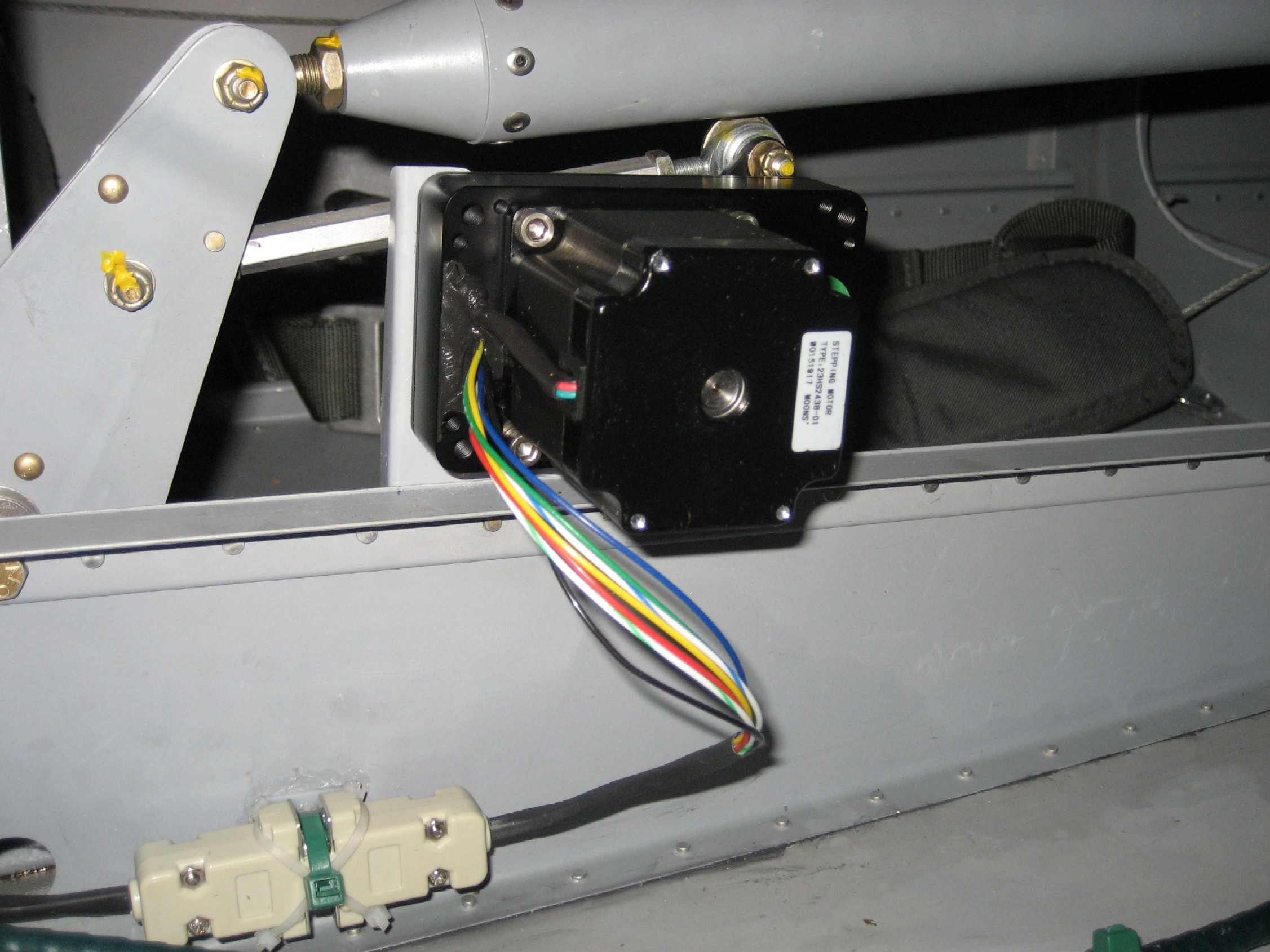
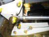
 E
Connecting the servos with a DB9 connector made
the installation easier as it allowed me to simply plug the thing in, once
it was secured to the bracket. Note how the zip-tie pad is glued to
the rib, the DB9 shells are zip-tied together, and then both are zip-tied
to the pad. This makes for an easy and clean installation. E
Connecting the servos with a DB9 connector made
the installation easier as it allowed me to simply plug the thing in, once
it was secured to the bracket. Note how the zip-tie pad is glued to
the rib, the DB9 shells are zip-tied together, and then both are zip-tied
to the pad. This makes for an easy and clean installation. |
| |
|
 F
Installing the roll servo is VERY easy when
compared to the pitch servo. Simply remove the lower aileron bell
crank bracket, install the one provided by Dynon, bolt on the extra plate,
servo, push rod, connect the wires and you are ready to go. Because
of the limited space within the wing, it was difficult to get a good
picture. F
Installing the roll servo is VERY easy when
compared to the pitch servo. Simply remove the lower aileron bell
crank bracket, install the one provided by Dynon, bolt on the extra plate,
servo, push rod, connect the wires and you are ready to go. Because
of the limited space within the wing, it was difficult to get a good
picture.
|
| |
|
Note: Dynon provides brackets which are designed
to limit the servo travel to prevent the servos from going "over center"
and jamming the controls. It is up to you, the installer to
determine if these are required for your installation.
The pictures and descriptions above are not
intended to be used as an installation guide. Remember, you are
making major changes to your flight controls and there is always the risk
of introducing something that could jam your flight controls. Be
careful when installing this or any autopilot!
|
| |
| As with any autopilot
installation, you will need a way to disengage the unit while in flight.
Dynon recommends the use of a disconnect switch, which grounds a wire
running to both servos. I drilled a small hole in the trigger
position in the teak stick grips installed in N941WR. This location
was selected as the PTT switch was already on the top of the sticks and
has worked out well. Electrical
connection to both servos and the AP74 are through a dedicated 5A pullable
circuit breaker. This is a highly desirable configuration as power
to the servos can be easily removed should the need arise. If your
installation uses automotive fuses, it is highly recommended you add a
disconnect switch which is easily accessible to the pilot. |
| |
|
Autopilot Impressions:
Dynon has done an outstanding job of integrating
their EFIS with modern stepper motor technology to develop an easy to
install and use two axis autopilot!
The hardware installation is easy as is the
software configuration and operation. When activated there is a
small icon on the lower left of the screen indicating if the AP is
operating in either pitch, roll, or both and what navigation source is
driving the heading, if any.
In addition, they have incorporated a 180 degree
about face button on the AP74/76 as well as made it available through the
menu system on the EFIS. This has the ability to save many lives
should a VFR pilot in advertently fly into IFR conditions. Just
press the 180 button and let go. It will reverse course and fly out
of "the soup" on it's own.
There are too many features for me to describe on
this web page. Needless to say, I'm very happy to add their
autopilot to my airplane.
A number of people have asked me if I can notice
the servos through the control stick. The answer is yes and no.
On the ground, with no air loads on the control surfaces, the servos can
be felt but in the air, I could not tell the difference.
The servos are designed to be overpowered by the
pilot, should they command something the pilot does not wish to do.
There is also a shear pin in the servos that can be broken, should the
servos jam.
|
| |
|
|
| |
| |
| |
| |
| |
| |
|
|
|