Bill's Aircraft Factory
First
Flight
Trips
Horizontal
Stabilizer
Vertical
Stabilizer
Elevator
Trim Tab
Rudder
Wings &
Fuel Tank
Ailerons
Flaps
Fuselage
Page 1
Page 2
Page 3
Page 4
Engine & FWF
Page 1
Page 2
Page 3
Instrument Panel
Electrical System
Building in the Basement and Moving to the Airport
Dynon Autopilot
Installation
Things to Consider
Tools
Products
Tell me again
Helpful Links
Plane Pictures
FAQ's
E-mail:
bill (at)
repucci (dot) com
|
|
Horizontal Stabilizer construction
Caution - Man running (with) power tools
 E
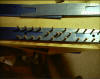
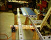
The HS spars being test fitted. These parts fit together right out of the
box. Match drilling and deburring is required but nothing difficult.
(5/4/03) E
The HS spars being test fitted. These parts fit together right out of the
box. Match drilling and deburring is required but nothing difficult.
(5/4/03)
|
| |
|
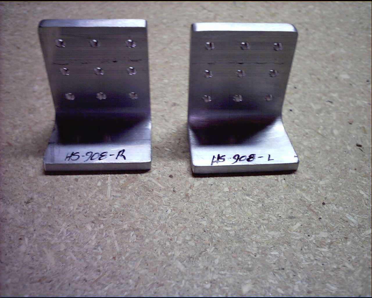
 F
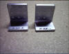
Here is a sample of some the parts you are required to make. These
aluminum brackets started life as a section of angle "iron" and will hold
the HS to the airframe. (5/03/03) F
Here is a sample of some the parts you are required to make. These
aluminum brackets started life as a section of angle "iron" and will hold
the HS to the airframe. (5/03/03)
|
|
| |
| |
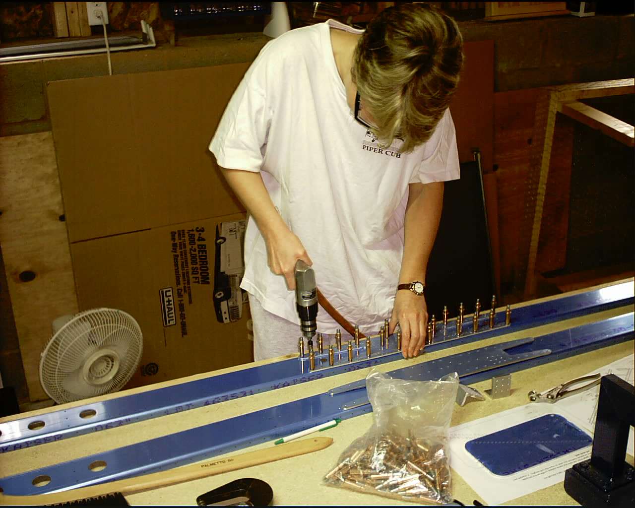
 E
Yes, Nora has been both supportive and helpful. During my fist tech
inspection the Inspector suggested I get more pictures of myself working
on the plane if I have any hope of proving it was I who actually built
this thing to the FAA. (5/04/03) E
Yes, Nora has been both supportive and helpful. During my fist tech
inspection the Inspector suggested I get more pictures of myself working
on the plane if I have any hope of proving it was I who actually built
this thing to the FAA. (5/04/03)
|
| |
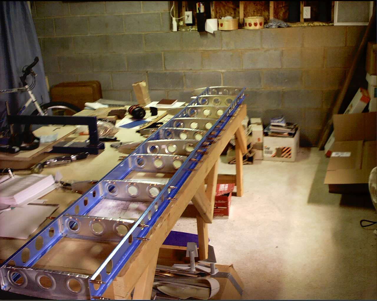
 F
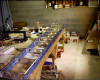
This picture should give you and idea of scale. My work table is over
eight feet long and this hangs off both ends. (5/04/03) F
This picture should give you and idea of scale. My work table is over
eight feet long and this hangs off both ends. (5/04/03)
|
| |
| |
 E
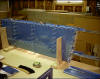
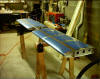
The HS in the jig with the skin on for the first time waiting to get match
drilled. (5/4/03) E
The HS in the jig with the skin on for the first time waiting to get match
drilled. (5/4/03)
|
| |
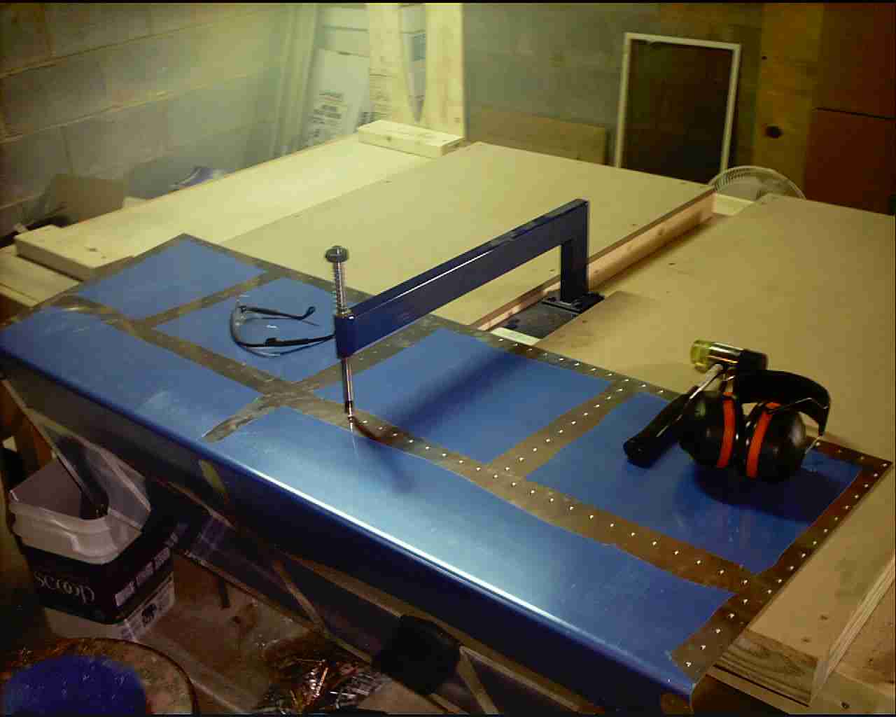
 F
Dimpling the HS after it has been matched drilled and deburred so the
flush head rivets will lie flush with the skin. (5/11/03) F
Dimpling the HS after it has been matched drilled and deburred so the
flush head rivets will lie flush with the skin. (5/11/03)
|
 E
The HS half riveted together. A lot of prep work went into the project
prior to this stage. The rear spar, which is resting in front of the HS,
will be riveted in place after the other HS skin is riveted on. (5/27/03) E
The HS half riveted together. A lot of prep work went into the project
prior to this stage. The rear spar, which is resting in front of the HS,
will be riveted in place after the other HS skin is riveted on. (5/27/03)
|
| |
 F
The completed HS. (6/9/03) F
The completed HS. (6/9/03)
|
| |
On 6/24/06 I had the pleasure
of helping rivet the nose ribs in place on the HS for both an RV-7 and
an RV-9A. I enjoy helping others with their project so that wasn't
a problem. The -9A builder mentioned that I warn all new builders
to get help when riveting the HS skins in place.
That is a very good point.
As I approach the end of my building I realize that the very first rivet
to be driven is probably one of the most difficult. Not just
because you are new to building but because bucking bar access is
limited and the rivet gun should be held at such an angle so as to make
it difficult to buck and drive it by yourself. In short, find some
experienced help!
Better yet, start on the VS.
Access is better and the rivets are easier to buck. Then move back
to the HS. You will have more confidence and do a better job.
|
| |
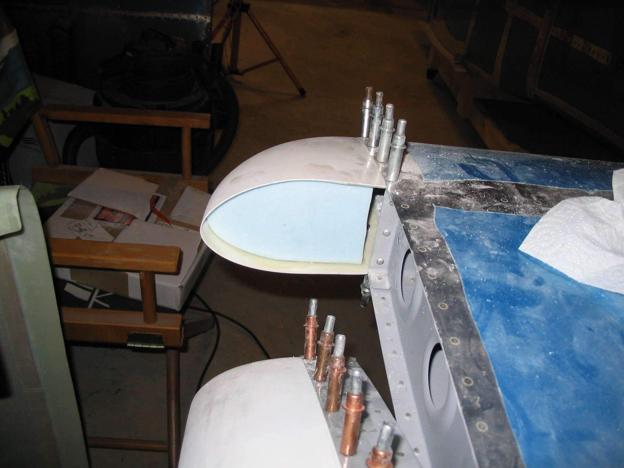
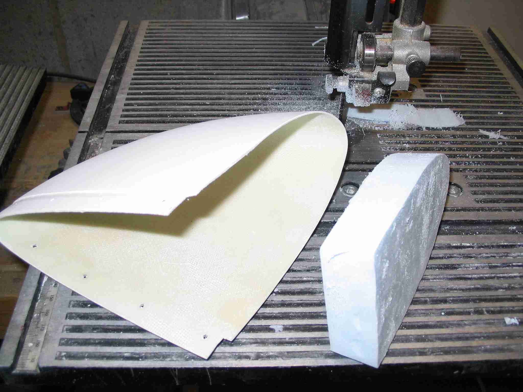
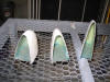
 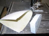 F
To fill the void in the end of the HS and VS caps, Dow Styrofoam,
like what is used for house insulation, is cut to size and epoxied in
place. Once it hardens, it will get a layer or two of
fiberglass on the outside. The Styrofoam will be removed
using mogas, more fiberglass will be added to the backside.
The remaining "cup" will be filled with epoxy and micro balloons. (6/26/06) F
To fill the void in the end of the HS and VS caps, Dow Styrofoam,
like what is used for house insulation, is cut to size and epoxied in
place. Once it hardens, it will get a layer or two of
fiberglass on the outside. The Styrofoam will be removed
using mogas, more fiberglass will be added to the backside.
The remaining "cup" will be filled with epoxy and micro balloons. (6/26/06)
|
| |
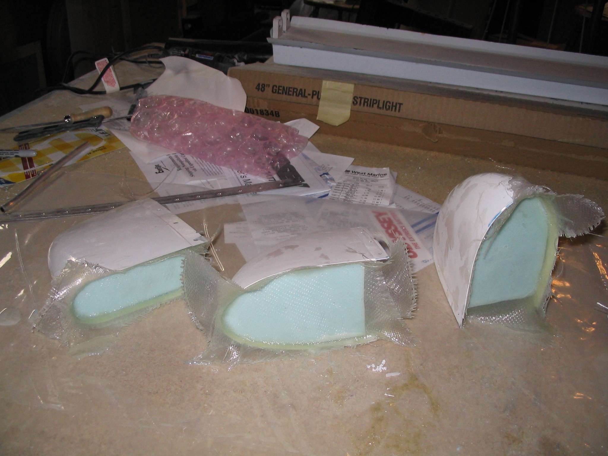
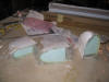  E
After epoxying the Styrofoam in place two layers of fiberglass
were laid on the top. The foam was removed by poring mogas
on it, the stuff just evaporates. The parts were then washed
out to remove any remaining mogas. Acetone followed by soap
and water was recommended to me and it seemed to work just fine.
After drying three layers of fiber glass were placed on the inside
of each cap. (6/28/06) E
After epoxying the Styrofoam in place two layers of fiberglass
were laid on the top. The foam was removed by poring mogas
on it, the stuff just evaporates. The parts were then washed
out to remove any remaining mogas. Acetone followed by soap
and water was recommended to me and it seemed to work just fine.
After drying three layers of fiber glass were placed on the inside
of each cap. (6/28/06)
|
| |
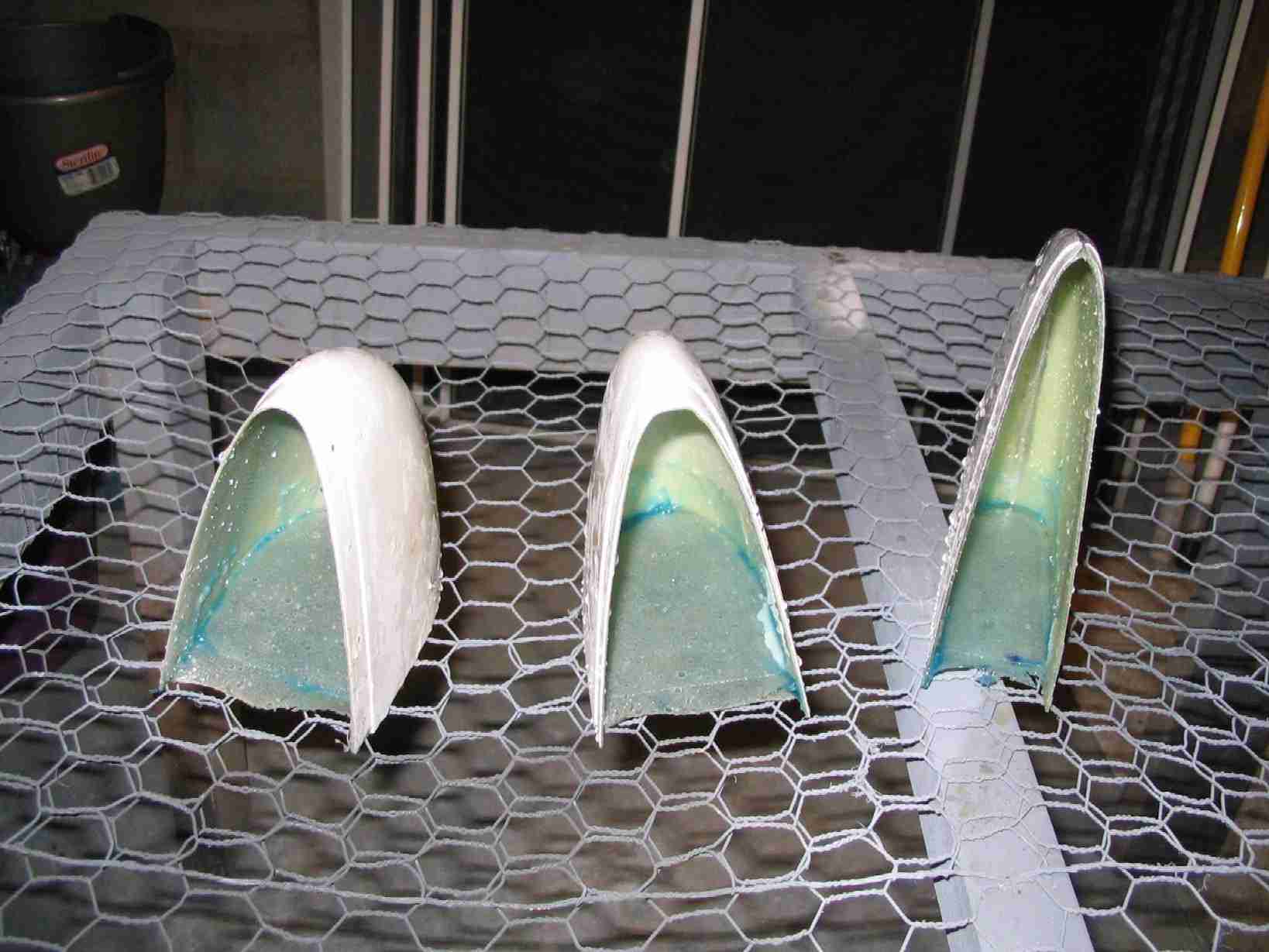
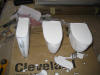 F
With the fiberglassing complete, the caps were filled with a micro
balloon slurry. Remember, the fiberglass was not even with
the edge of the caps. This was done so they could be sanded
convexly to provide clearance for the elevators and rudder.
Sure enough, after the slurry hardened, the caps were easily sanded to fit and are now
waiting to be riveted in place. (6/29/06) F
With the fiberglassing complete, the caps were filled with a micro
balloon slurry. Remember, the fiberglass was not even with
the edge of the caps. This was done so they could be sanded
convexly to provide clearance for the elevators and rudder.
Sure enough, after the slurry hardened, the caps were easily sanded to fit and are now
waiting to be riveted in place. (6/29/06)
|
| |