|
  E
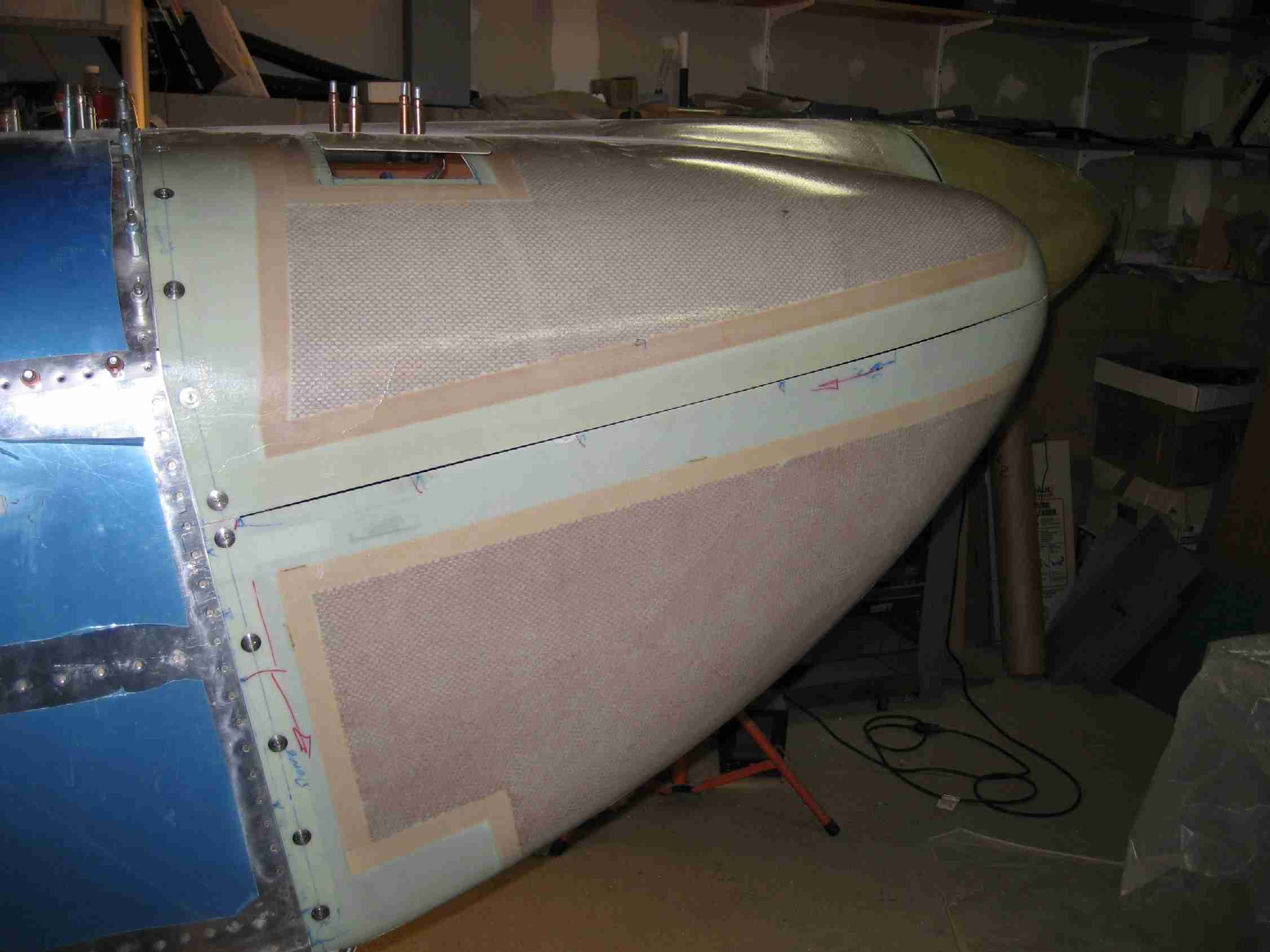
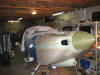
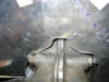
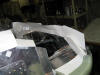
Here are the top and bottom cowls attached with the Skybolt fasteners for
the first time. A good bit of work remains. Van's calls for
the use of piano hinges to join the top and bottom cowls along the
horizontal part line. Since the cowl will be joined with Skybolt
fasteners, I have to rivet and then fiber glass in aluminum strips along
the bottom cowl. With luck, that that will be accomplished tomorrow.
(02/09/07) E
Here are the top and bottom cowls attached with the Skybolt fasteners for
the first time. A good bit of work remains. Van's calls for
the use of piano hinges to join the top and bottom cowls along the
horizontal part line. Since the cowl will be joined with Skybolt
fasteners, I have to rivet and then fiber glass in aluminum strips along
the bottom cowl. With luck, that that will be accomplished tomorrow.
(02/09/07) |
|
|
|
 F
Fitting the baffles to the top of the cowling can be a challenge. I
elected to use the "paper clip" method to get the gap correct.
Simply place paper clips on the baffle, put the top cowl on, lift off, and
measure down the correct distance from the top of the clips. On my
RV-9, the gap should be between 1/4 and a 1/2". This method allowed
me to trim them to 3/8".
(02/21/07) F
Fitting the baffles to the top of the cowling can be a challenge. I
elected to use the "paper clip" method to get the gap correct.
Simply place paper clips on the baffle, put the top cowl on, lift off, and
measure down the correct distance from the top of the clips. On my
RV-9, the gap should be between 1/4 and a 1/2". This method allowed
me to trim them to 3/8".
(02/21/07) |
|
|
|
   E
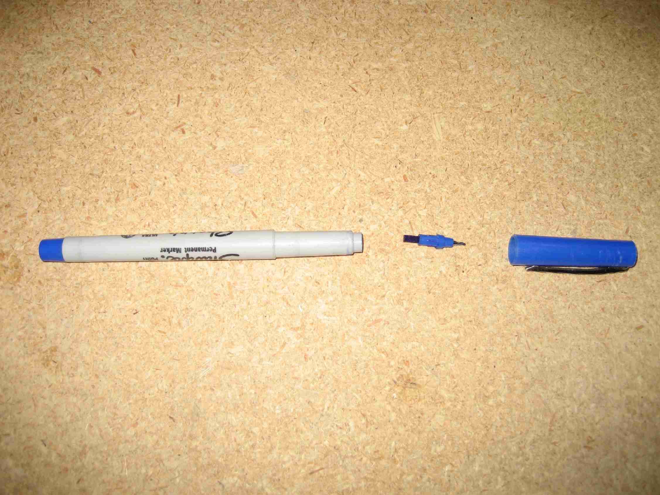
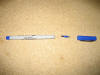
Fitting the baffles can be a bit of a challenge. More so since you
have to fit these angle pieces under them that bolt to the case. The
problem is figuring out where to drill the bolt hole. The trick I
came up with was to pull the tip out of a Sharpie and put it in the case
bolt hole. Then move the part up to the Sharpie tip, marking the
bracket. Take it off, drill the bolt hole, and then with the part
bolted in place, you can match drill the appropriate rivet holes.
(04/6/07) E
Fitting the baffles can be a bit of a challenge. More so since you
have to fit these angle pieces under them that bolt to the case. The
problem is figuring out where to drill the bolt hole. The trick I
came up with was to pull the tip out of a Sharpie and put it in the case
bolt hole. Then move the part up to the Sharpie tip, marking the
bracket. Take it off, drill the bolt hole, and then with the part
bolted in place, you can match drill the appropriate rivet holes.
(04/6/07) |
|
|
|
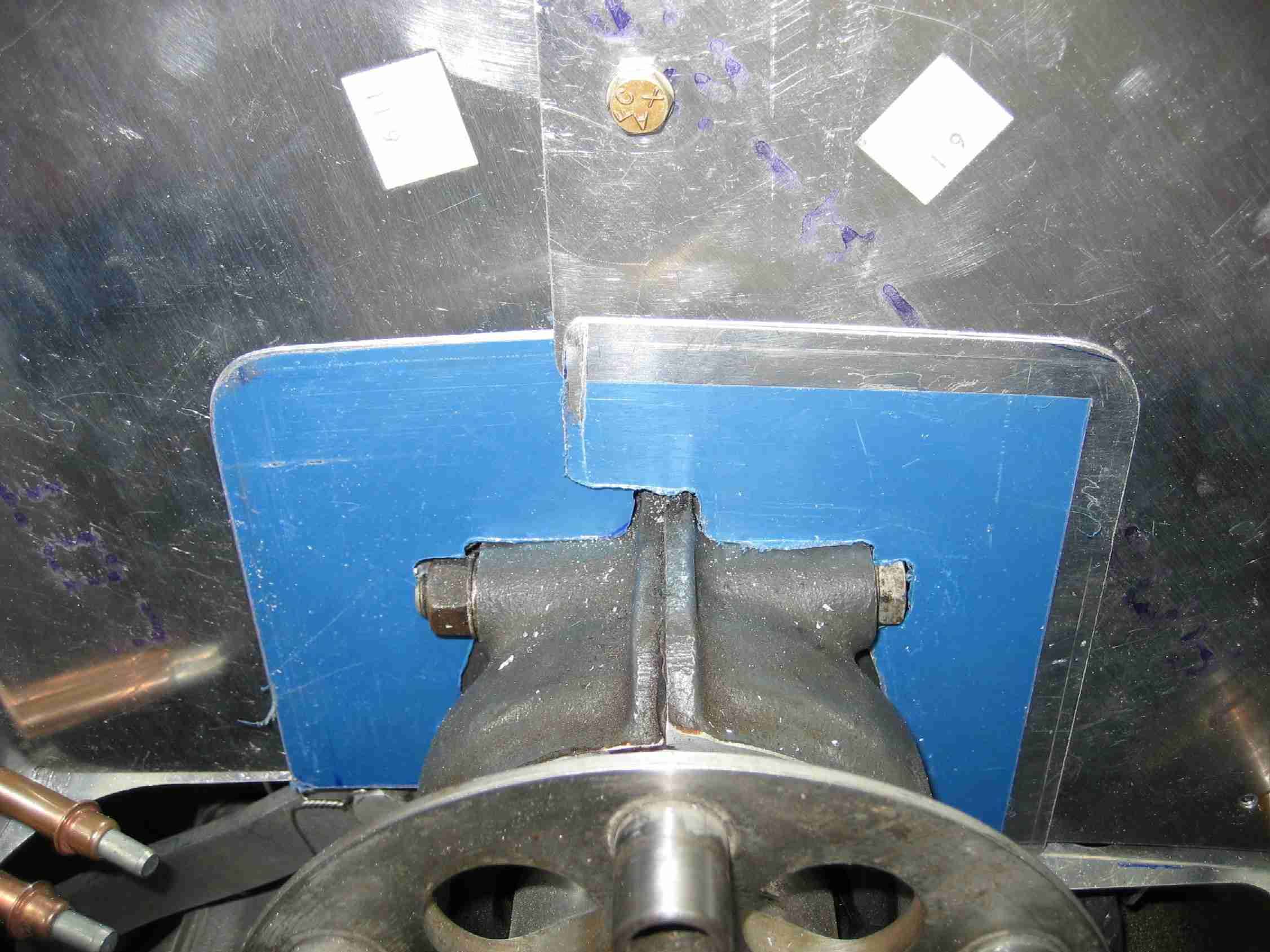
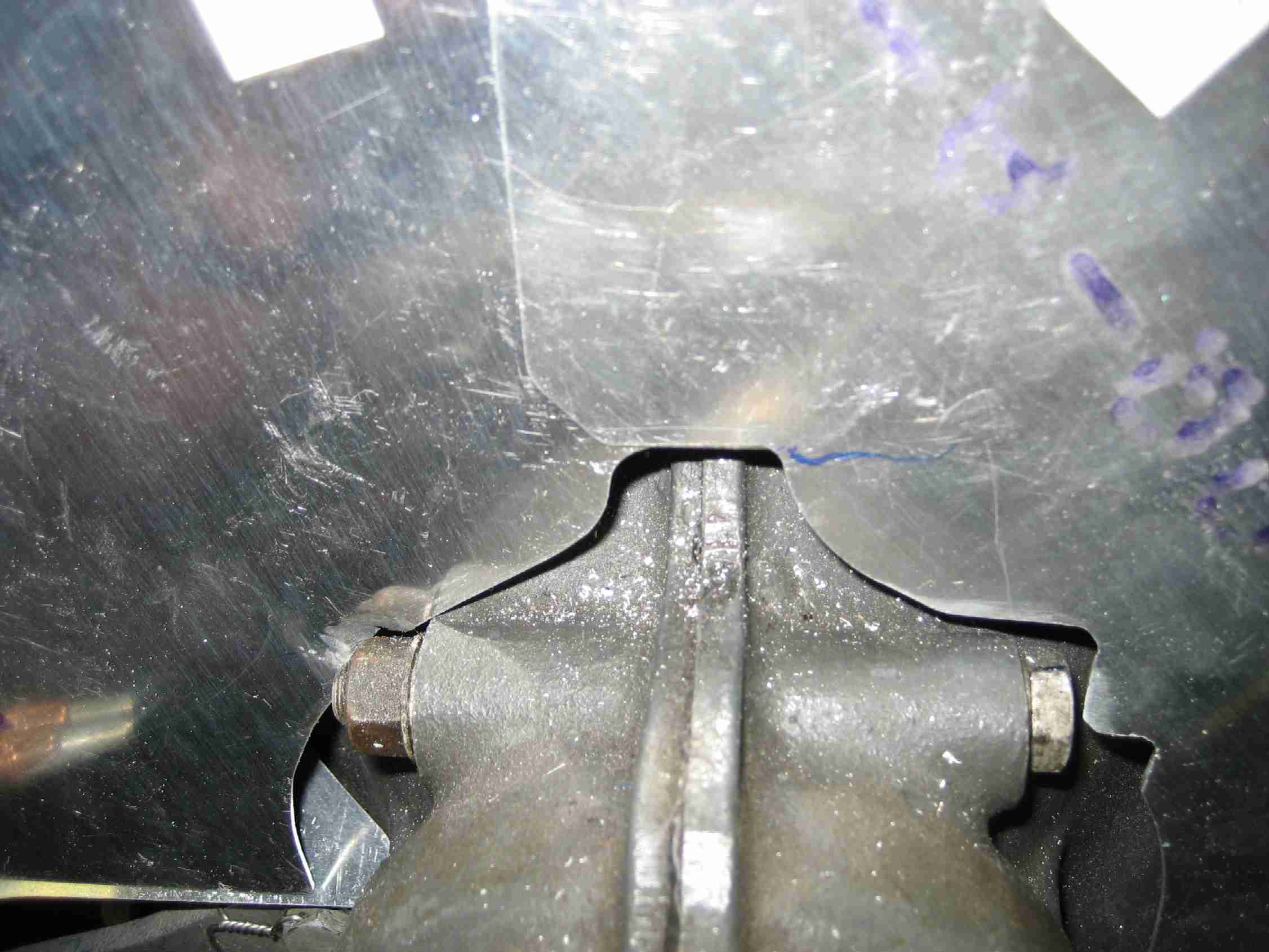
  F
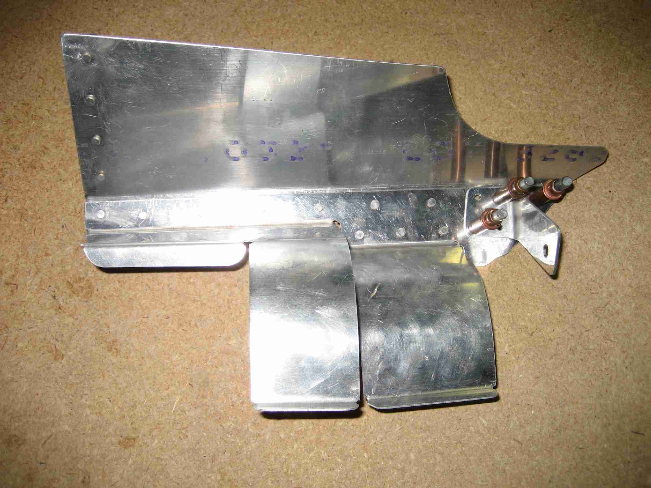
The picture on the left shows how the baffles close around the prop hub.
These are un-modified baffles, ad they came from Van's. The picture
on the right shows the two pieces I made to help close up the holes.
They were riveted in place and should really keep the air in the cooling
plenum.
(04/6/07) F
The picture on the left shows how the baffles close around the prop hub.
These are un-modified baffles, ad they came from Van's. The picture
on the right shows the two pieces I made to help close up the holes.
They were riveted in place and should really keep the air in the cooling
plenum.
(04/6/07) |
|
|
|
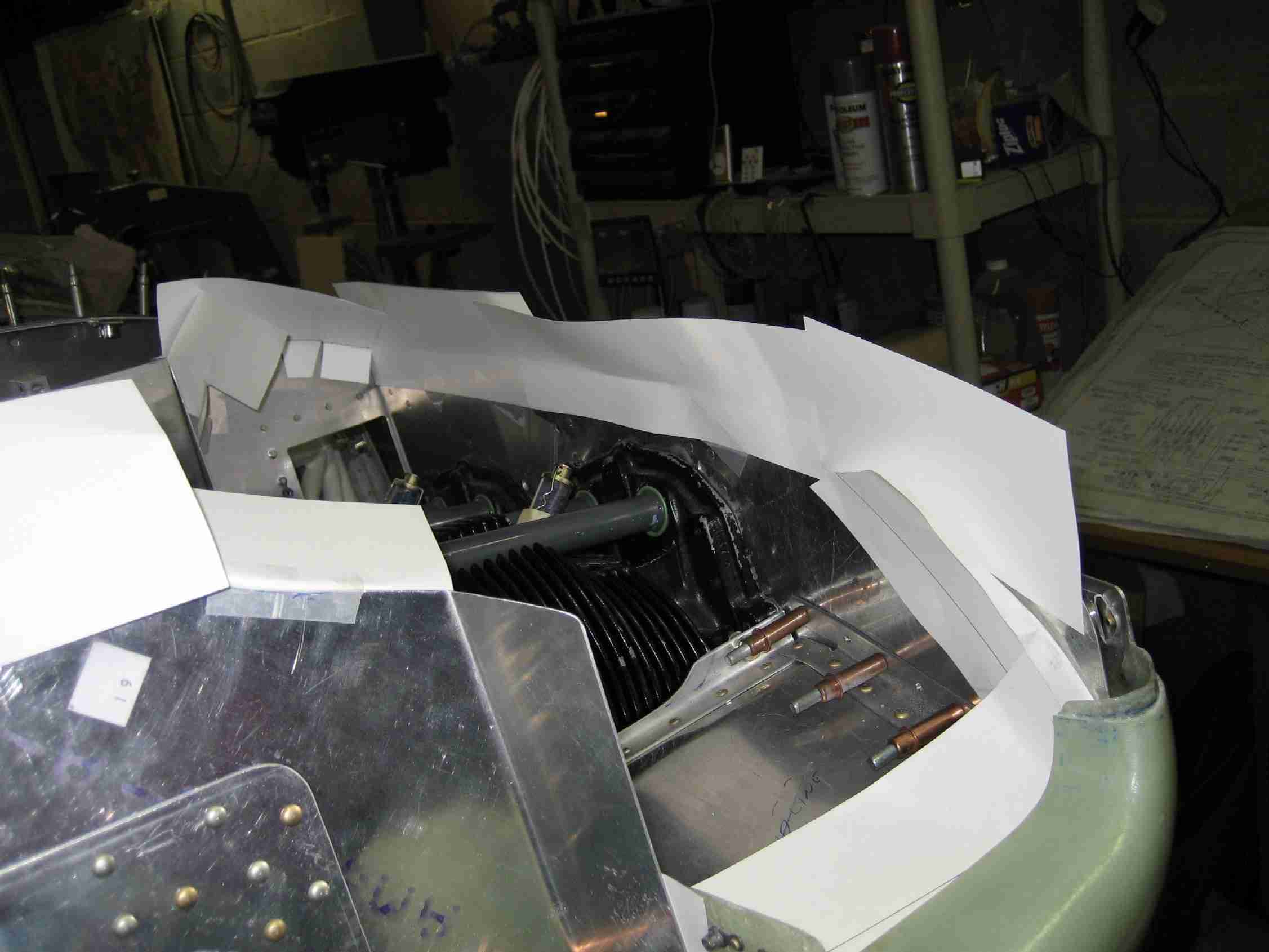
 E
Prior to cutting the air seal fabric, I made templates out of some stiff
card stock my wife had laying around. Ok, it wasn't exactly laying
around but don't tell her I raided her scrap booking supplies.
(04/6/07) E
Prior to cutting the air seal fabric, I made templates out of some stiff
card stock my wife had laying around. Ok, it wasn't exactly laying
around but don't tell her I raided her scrap booking supplies.
(04/6/07) |
|
|
|
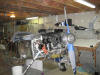
 F
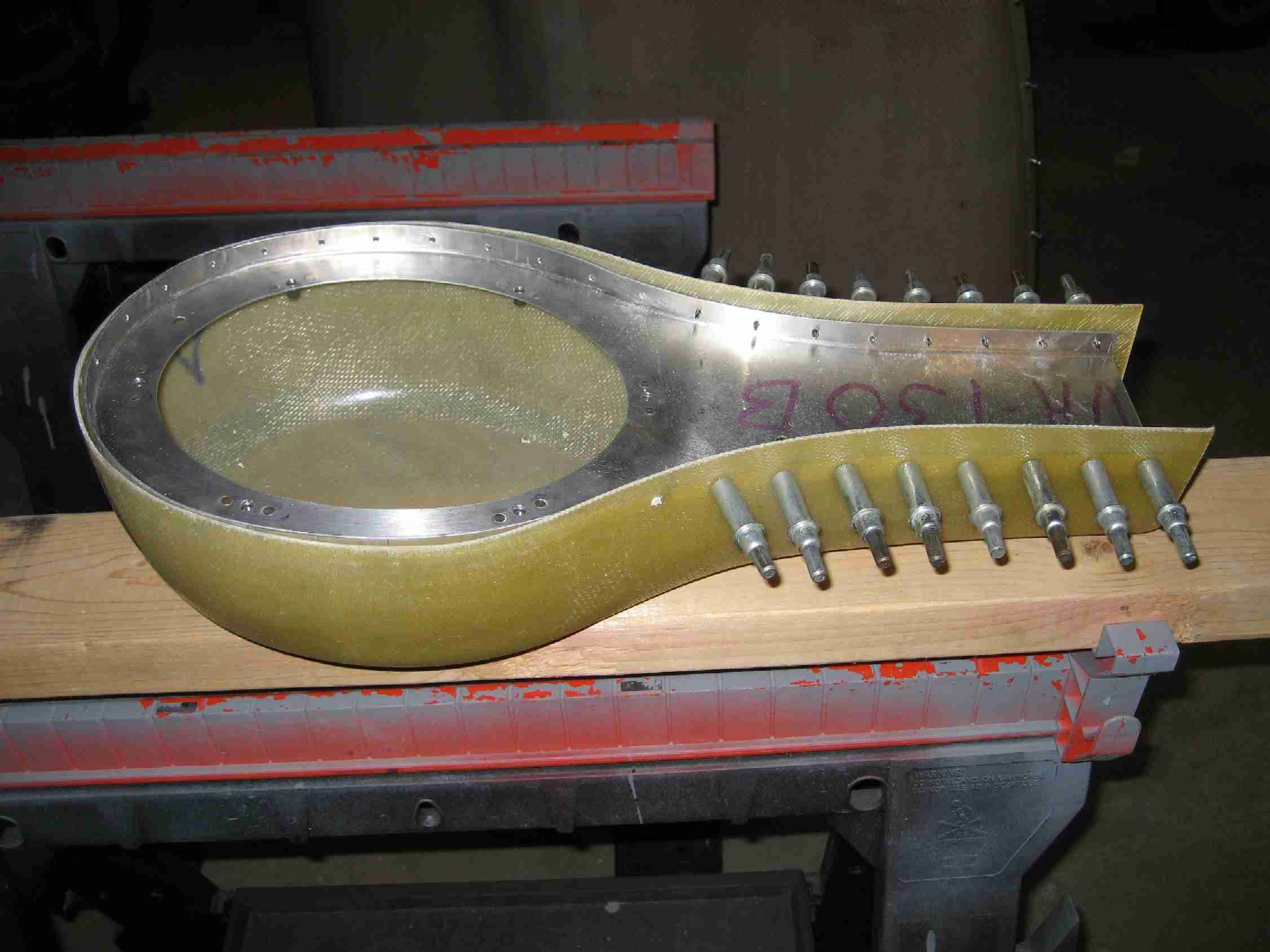
After finishing up the baffles I moved on to the FAB. As they say,
even a blind squirrel can find a nut every now and then. The FAB fit
my O-290 and lined up perfectly with the air inlet on the lower cowling.
Here is a picture of the FAB with the top clecoed in place. I made
the mistake of riveting it together at this point after trimming the
fiberglass down. I mention this as a "mistake" as it made it
difficult to cut the hole for the carb heat and rivet it in place.
Difficult but not impossible.
(04/14/07) F
After finishing up the baffles I moved on to the FAB. As they say,
even a blind squirrel can find a nut every now and then. The FAB fit
my O-290 and lined up perfectly with the air inlet on the lower cowling.
Here is a picture of the FAB with the top clecoed in place. I made
the mistake of riveting it together at this point after trimming the
fiberglass down. I mention this as a "mistake" as it made it
difficult to cut the hole for the carb heat and rivet it in place.
Difficult but not impossible.
(04/14/07) |
|
|
|
 E
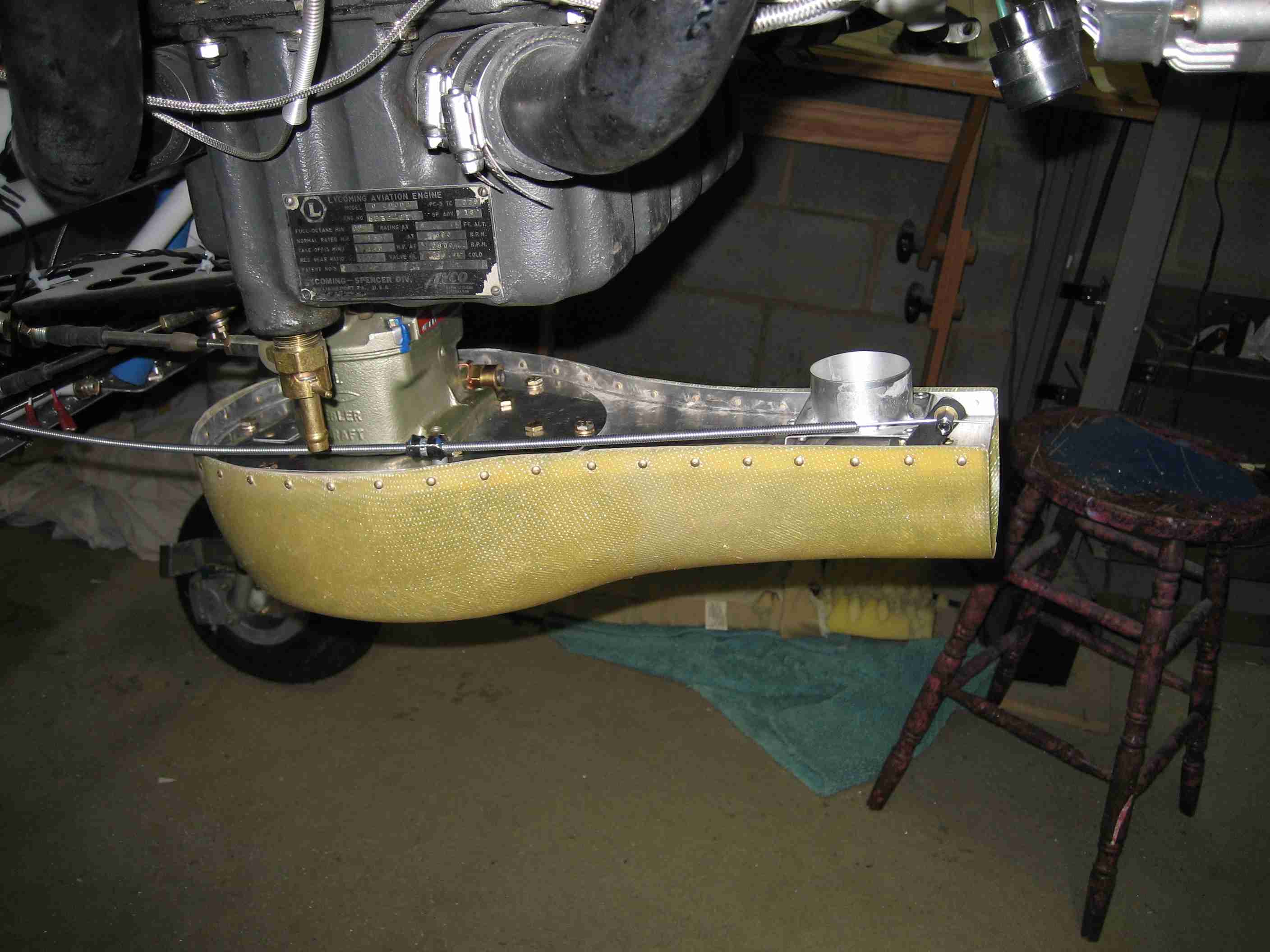
Here it is, the finished FAB, complete with carb heat cable installed.
OK, it is not exactly finished as I still need to rivet on the air seal
fabric to feed air from the cowling inlet into the FAB. Not a big
deal. I set my carb heat cable up so that it move approximately 1 -
1/8". This seems to work very nicely. E
Here it is, the finished FAB, complete with carb heat cable installed.
OK, it is not exactly finished as I still need to rivet on the air seal
fabric to feed air from the cowling inlet into the FAB. Not a big
deal. I set my carb heat cable up so that it move approximately 1 -
1/8". This seems to work very nicely.
Lining up the FAB to the lower cowling
inlet was easy enough to do with the exhaust removed, as recommended by
the instructions. However, rather than creating a foam block, fiber
glassing that in place, and carving it out after the epoxy hardened; I
elected to get the FAB close to the inlet, put packing tape all over the
aluminum and fiber glrass in the FAB and then lay up the fiberglass
directly from the cowling to the FAB. Once it hardened, it was easy
enough to remove and and trim prior to adding three more layers on the
outside to build it up a little bit more. Tomorrow I hope to fit the
air seal fabric between the cowling and the FAB (04/14/07) |
|
|
|
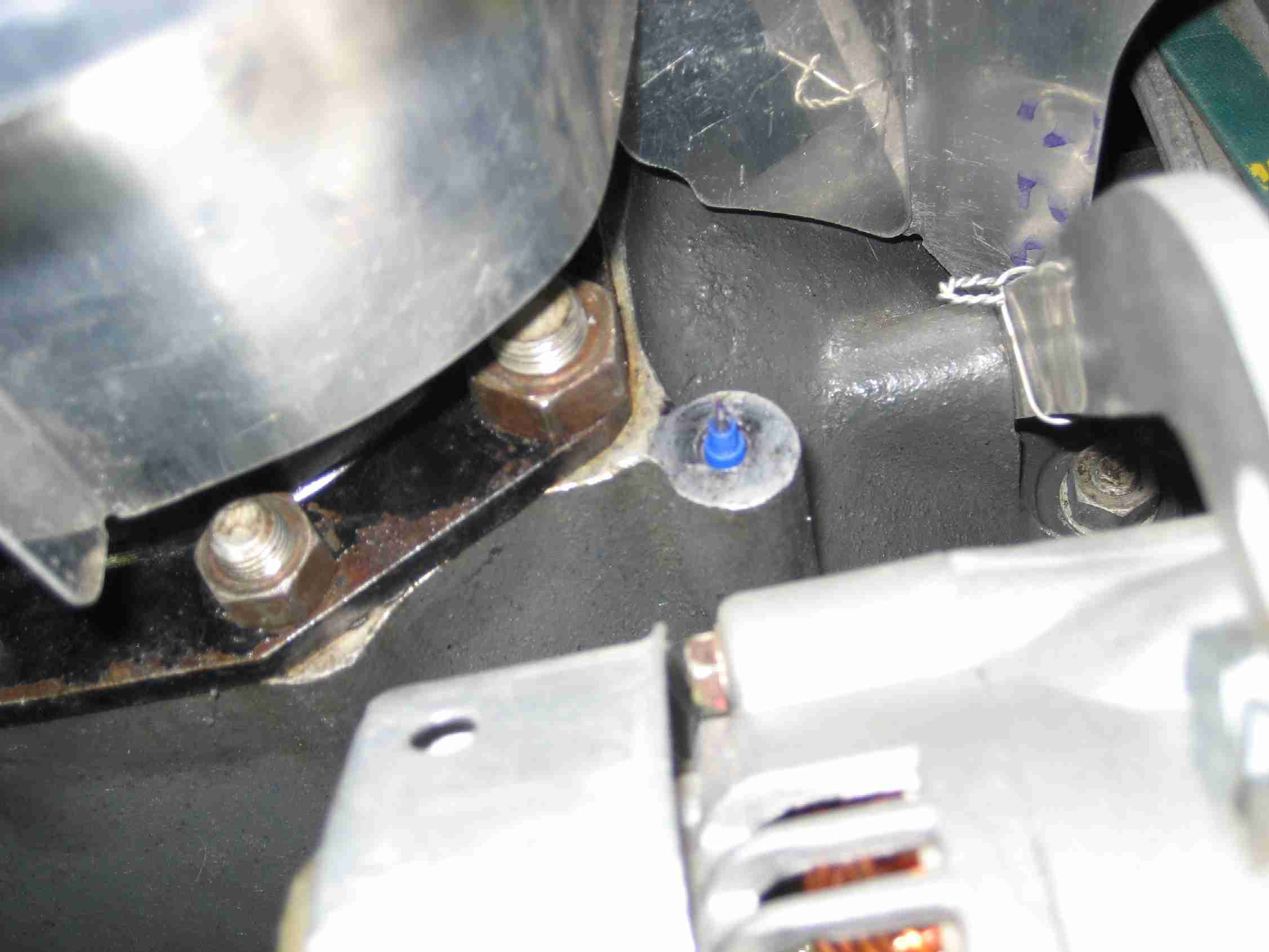
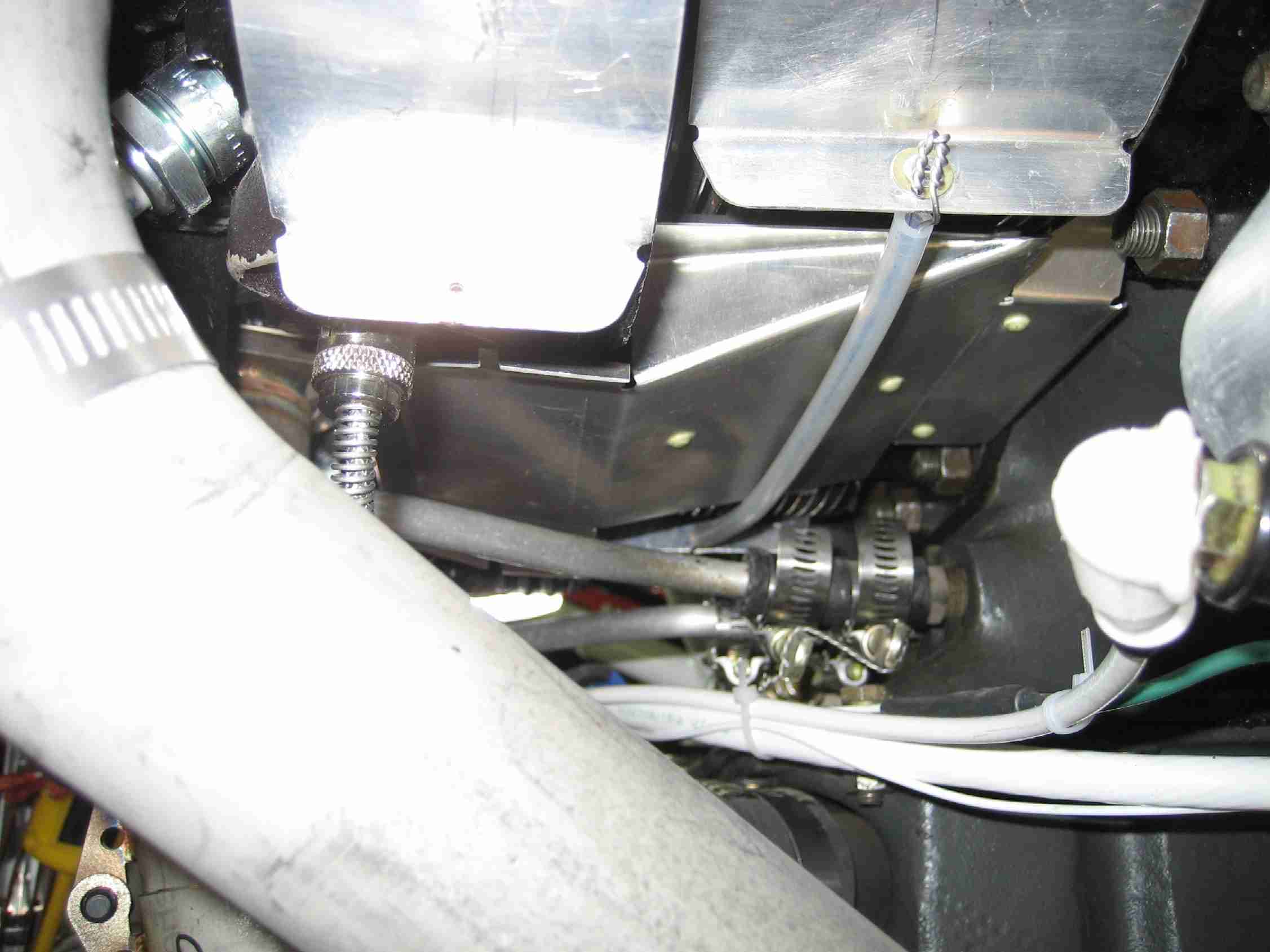
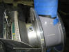
 F
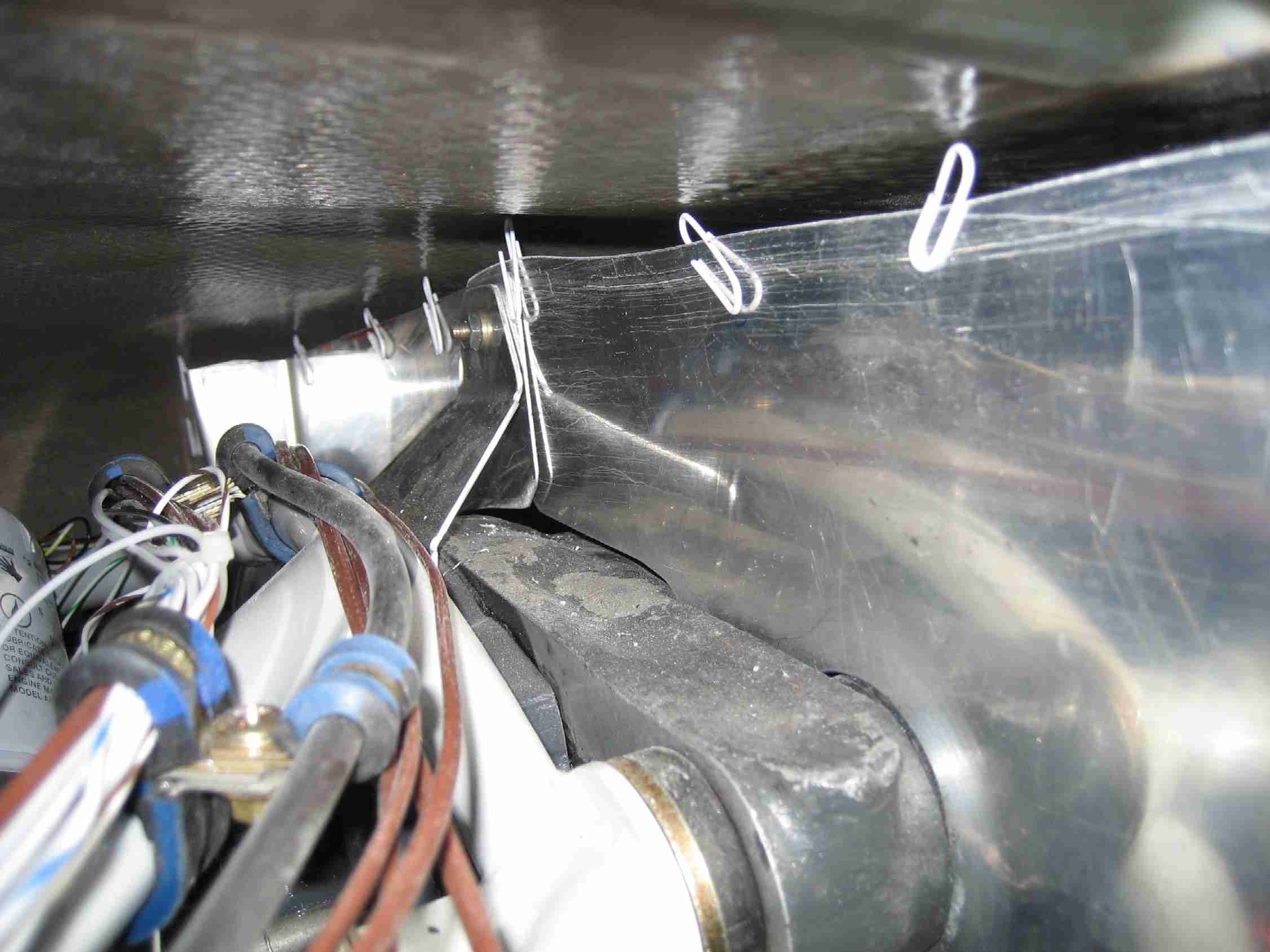
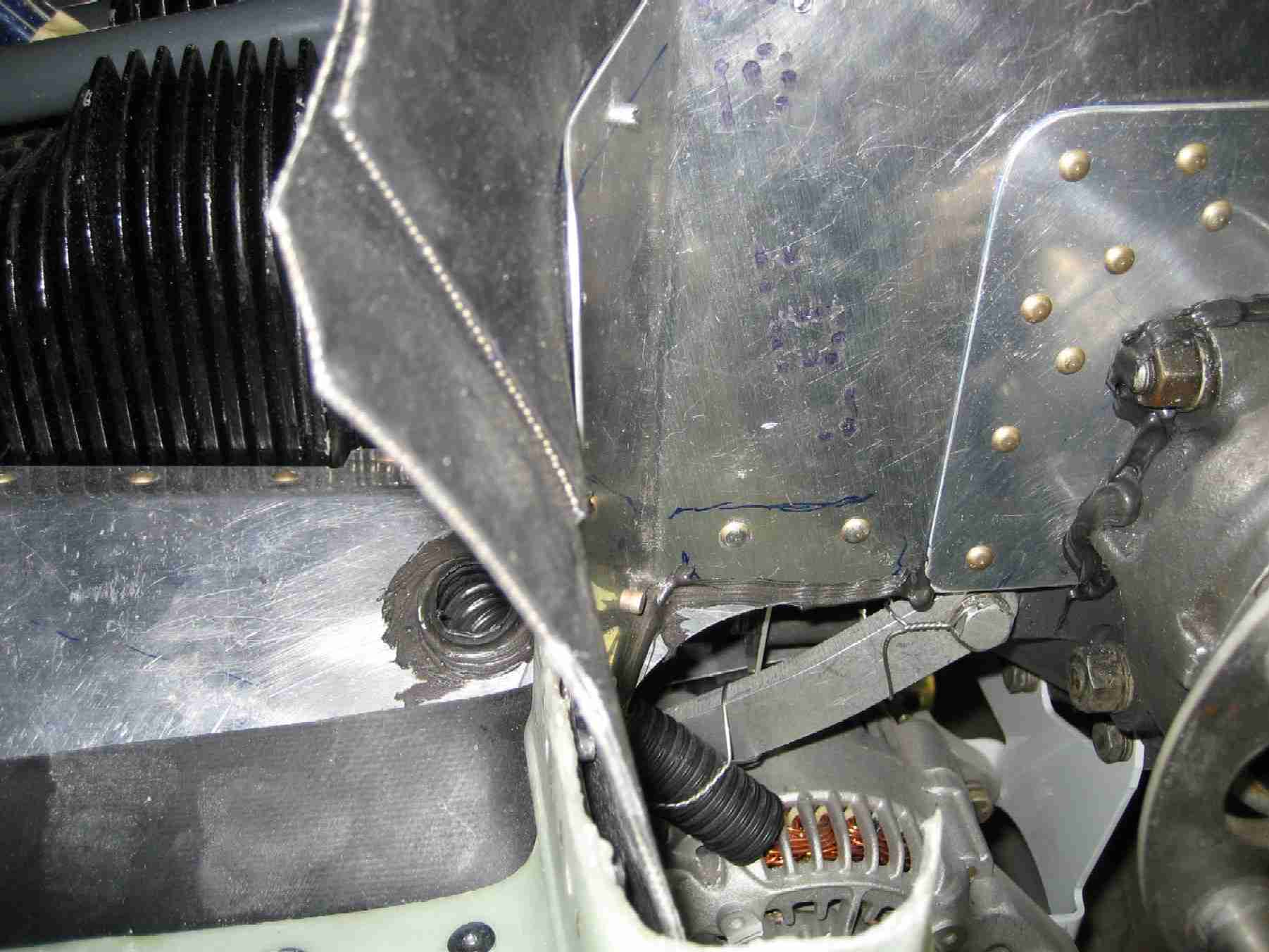
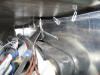
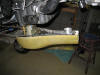
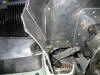
Cooling the alternator is a recommend practice. Here a section of
wing conduit is used to to direct cooling air on the alternator.
Note how it is safety wired to the alternator bracket so it puts air in
the correct place. RTV was used to seal it at the baffle. (04/15/07) F
Cooling the alternator is a recommend practice. Here a section of
wing conduit is used to to direct cooling air on the alternator.
Note how it is safety wired to the alternator bracket so it puts air in
the correct place. RTV was used to seal it at the baffle. (04/15/07) |
|
|
|
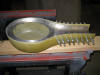
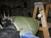
  E
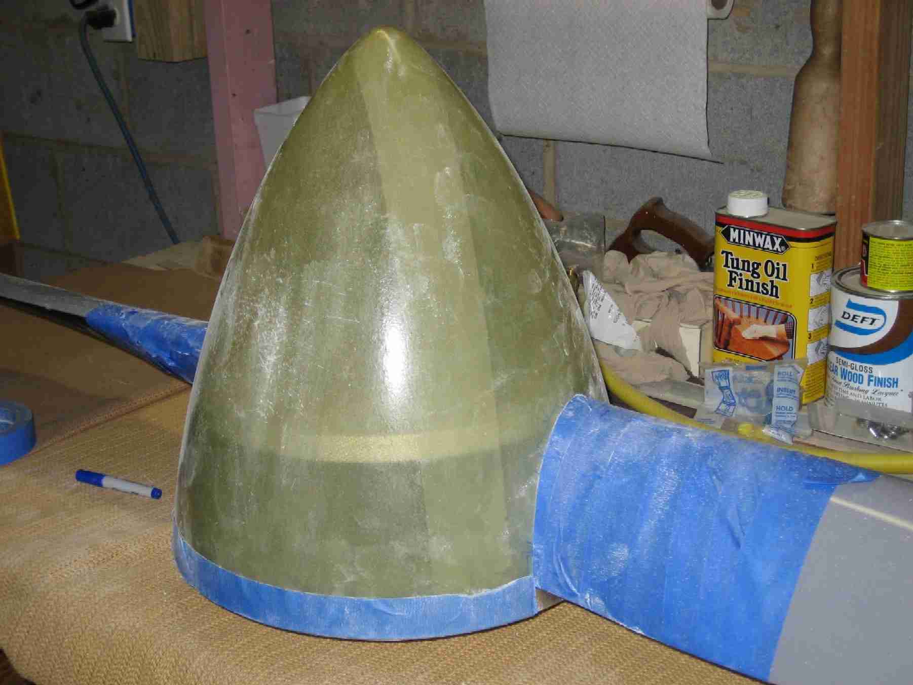
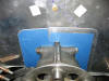
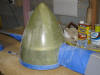
Time to start fitting the spinner. Start by protecting the paint.
Remember, this is a wood Catto prop. Then make a cardboard cutout
that fits the prop. Trace the cutout to the spinner and start
cutting. Once the prop is mounted, I will drill the holes to hold it
in place, per Van's instructions. (04/15/07) E
Time to start fitting the spinner. Start by protecting the paint.
Remember, this is a wood Catto prop. Then make a cardboard cutout
that fits the prop. Trace the cutout to the spinner and start
cutting. Once the prop is mounted, I will drill the holes to hold it
in place, per Van's instructions. (04/15/07) |
|
|
|
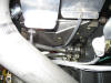
 F
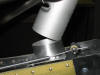
The Carb Heat was a bit of a surprise. I did not expect to fit
this close. Not a big deal and a small section of SCAT tubing worked
fine. (04/29/07) F
The Carb Heat was a bit of a surprise. I did not expect to fit
this close. Not a big deal and a small section of SCAT tubing worked
fine. (04/29/07)
Update:
At the first condition inspection in August 2008 I found the SCAT tubing
was cut in half. This was after 180+ hours. My solution was to
remove the carb heat muff and shorten it by 1/2" and put some new SCAT
tubing over it. (8/26/08) |
|
|
|
 E
Those pesky engine baffles! The instructions tell you to tie the
engine baffles together to direct air down through the cylinders by
drilling holes in the baffles and tying them together with safety wire or
some such. However, before putting safety wire through a hole in the
aluminum baffle, you must protect the baffles. I elected to use a
small AN washer held in place by a pop-rivet. The center of the pop
rivet was punched out, allowing the safety wire to pass through it. (05/6/07) E
Those pesky engine baffles! The instructions tell you to tie the
engine baffles together to direct air down through the cylinders by
drilling holes in the baffles and tying them together with safety wire or
some such. However, before putting safety wire through a hole in the
aluminum baffle, you must protect the baffles. I elected to use a
small AN washer held in place by a pop-rivet. The center of the pop
rivet was punched out, allowing the safety wire to pass through it. (05/6/07) |
|
|
|
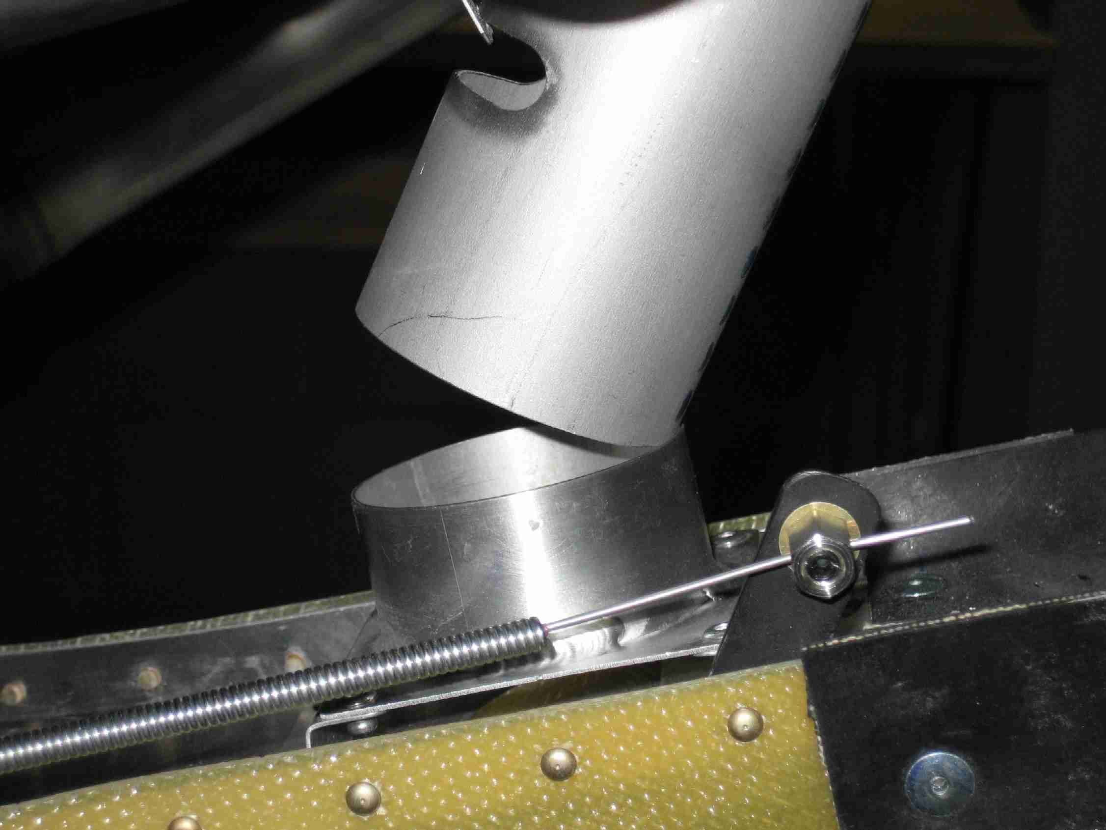
  F
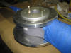
The prop was installed and tracked straight. Thank you Craig Catto!
Next up will be to drill the spinner to the backing plates. The
picture at the right is the Saber prop extension. (05/13/07) F
The prop was installed and tracked straight. Thank you Craig Catto!
Next up will be to drill the spinner to the backing plates. The
picture at the right is the Saber prop extension. (05/13/07) |
|
|
|
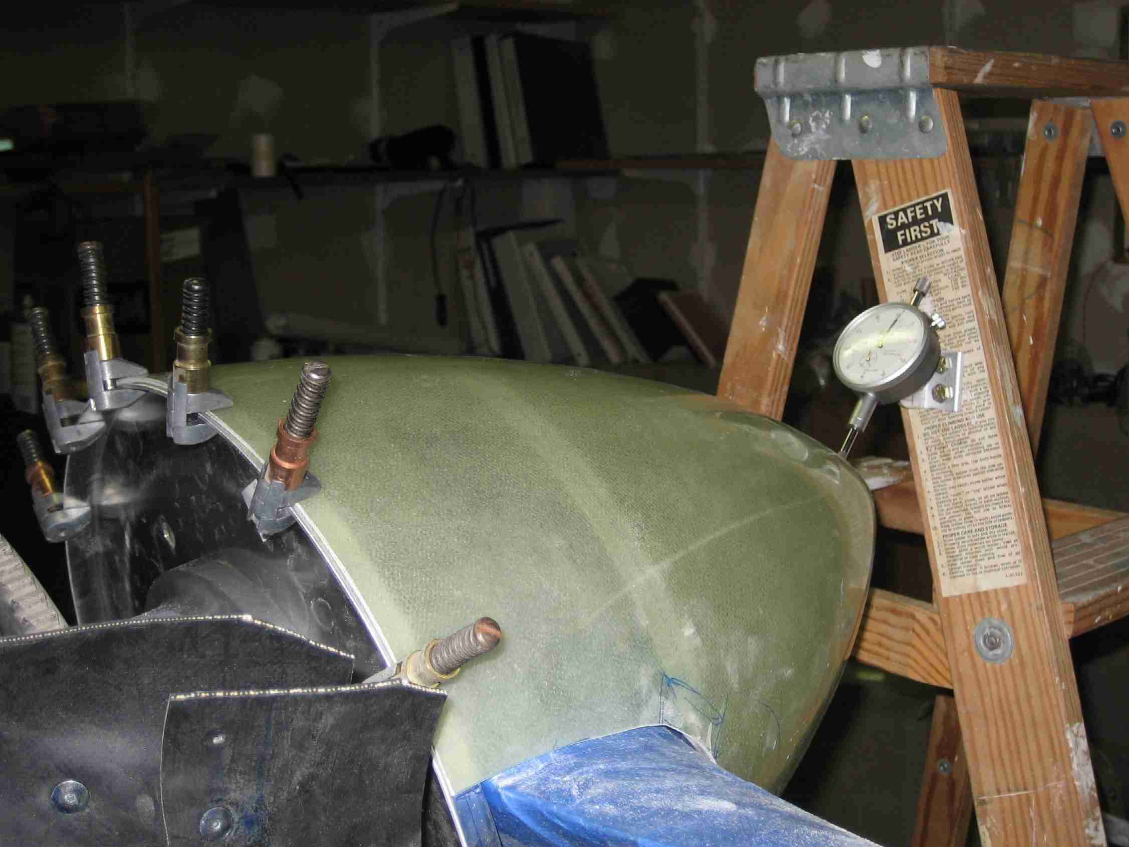
 E
Putting the prop spinner on perpendicular is a perplexing proposition for
plenty of people. (Sorry, I couldn't help myself.) E
Putting the prop spinner on perpendicular is a perplexing proposition for
plenty of people. (Sorry, I couldn't help myself.)
I borrowed a dial indicator from a
friend (Thanks Dale!), made a simple bracket bolt it to my ladder, and
stabilized the ladder with two bags of led shot.
Prior to clamping the spinner in place,
I marked it for where the holes are supposed to go.
With one sparkplug pulled from each
cylinder the prop turned over very easily. After a few hours (days?)
of turning, measuring, adjusting, etc. I was ready to drill the first
hole. These measuring devices are very accurate, take your time and
you will get close. I doubt you will ever attain "exact" because of
the varying thickness of the fiberglass spinner.
The good news is that my spinner runs
true. |
|
|