| |
 E
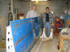
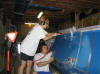
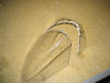
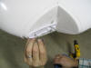
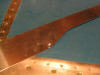
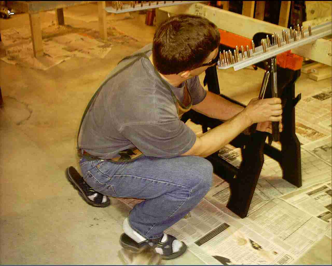
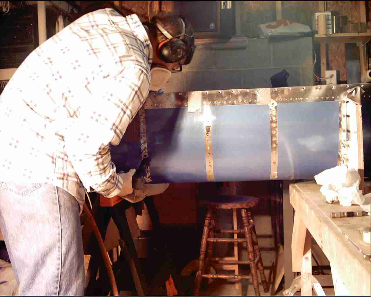
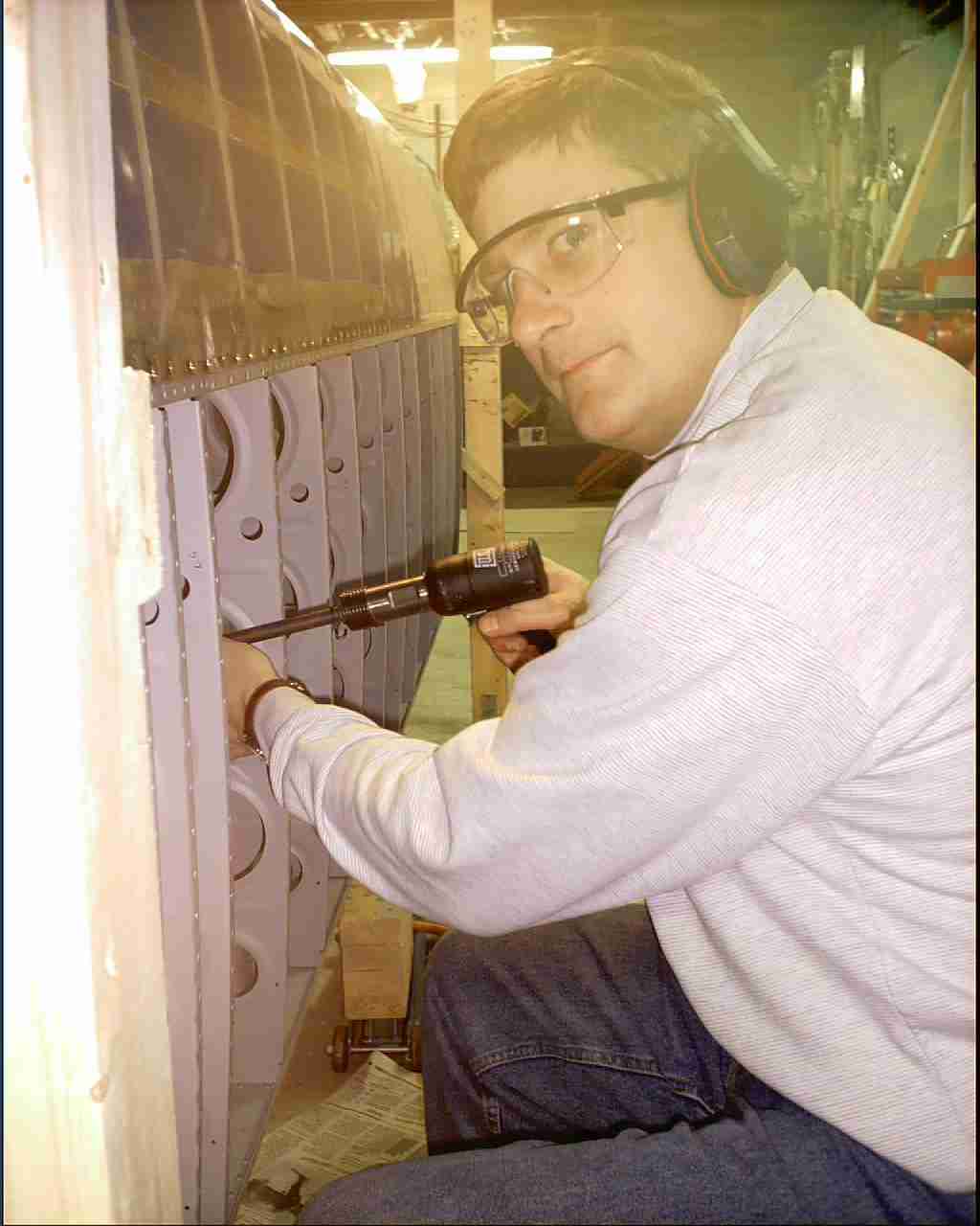
Here I am driving the rivets Nora is bucking. (2/26/04) E
Here I am driving the rivets Nora is bucking. (2/26/04) |
| |
 F
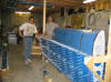
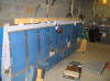
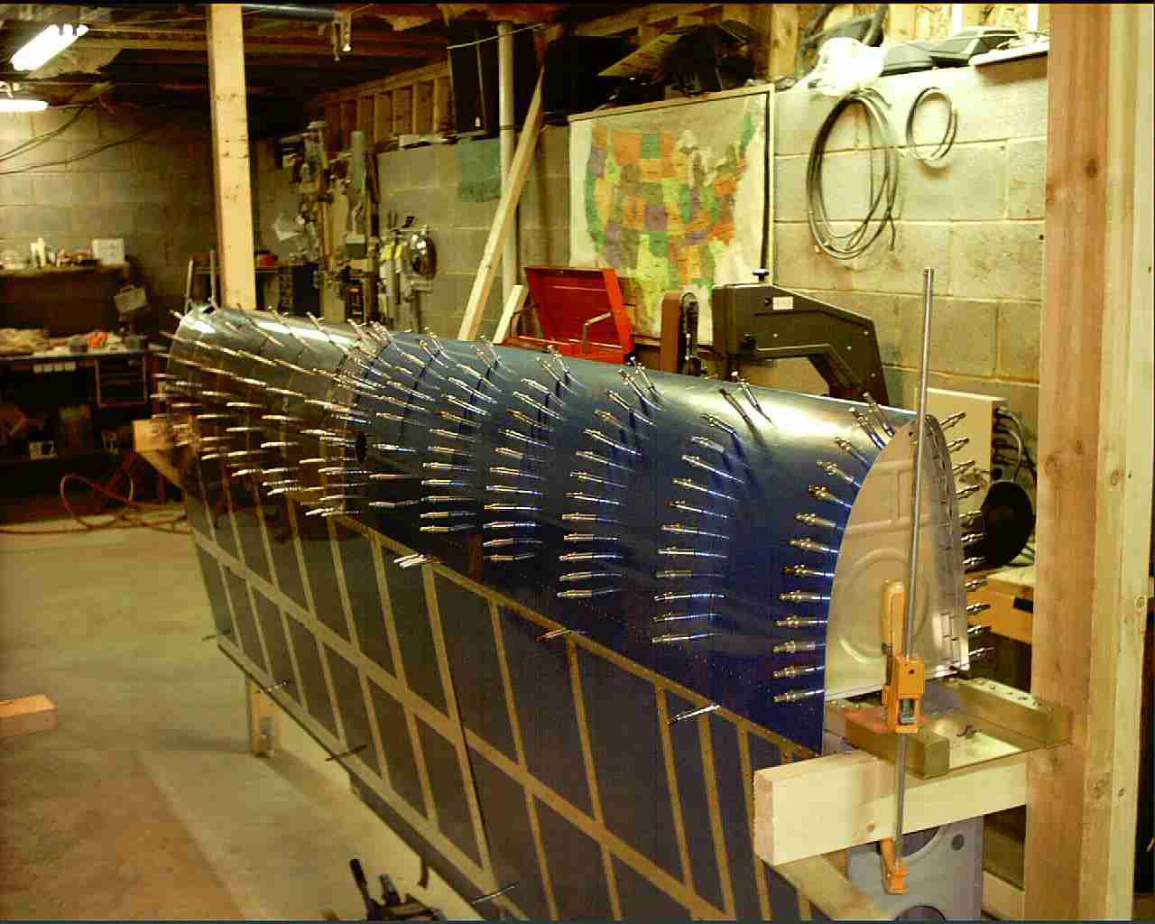
The weekend of March 21st, 22nd, & 23rd, 2004 Doug Sytsma, my
collage roommate, A&P, and Northwest Airlines Maintenance
Manager came down from Detroit to lend a hand pounding rivets.
In two days we finished riveting the left wing and started on
the right wing. (03/20/04) F
The weekend of March 21st, 22nd, & 23rd, 2004 Doug Sytsma, my
collage roommate, A&P, and Northwest Airlines Maintenance
Manager came down from Detroit to lend a hand pounding rivets.
In two days we finished riveting the left wing and started on
the right wing. (03/20/04) |
| |
 E
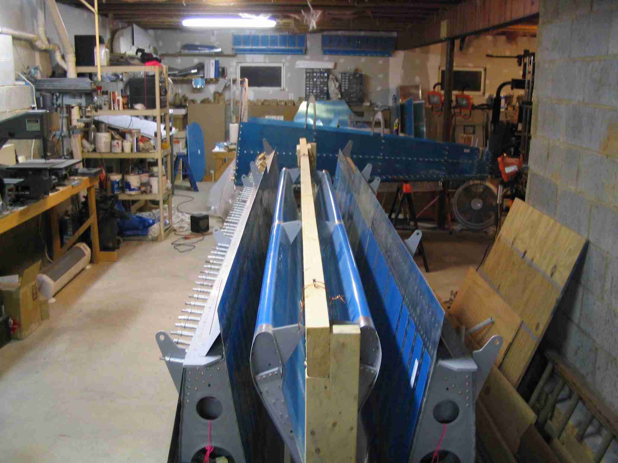
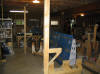
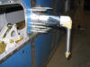
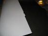
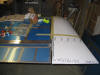
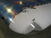
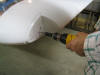
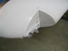
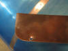
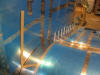
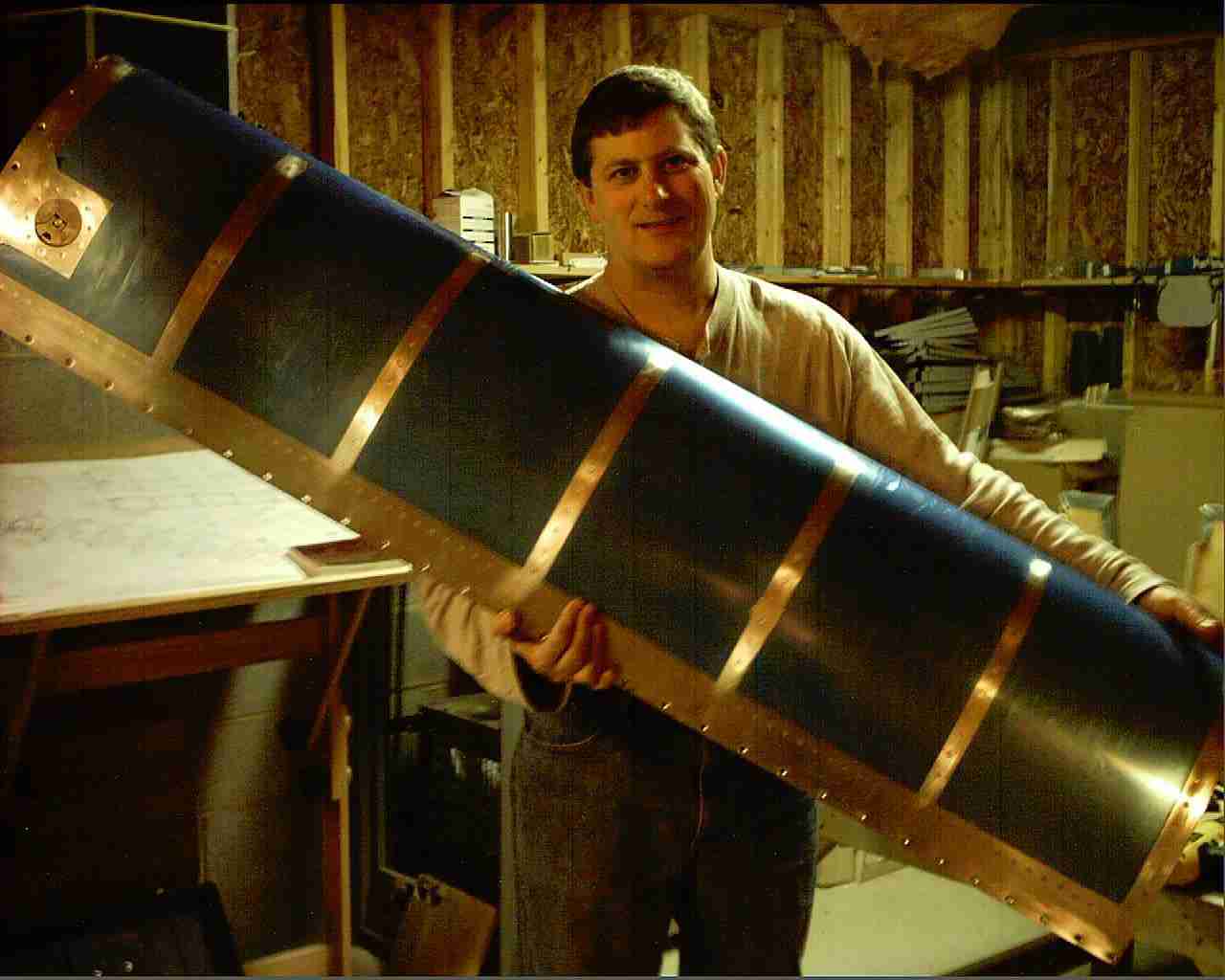
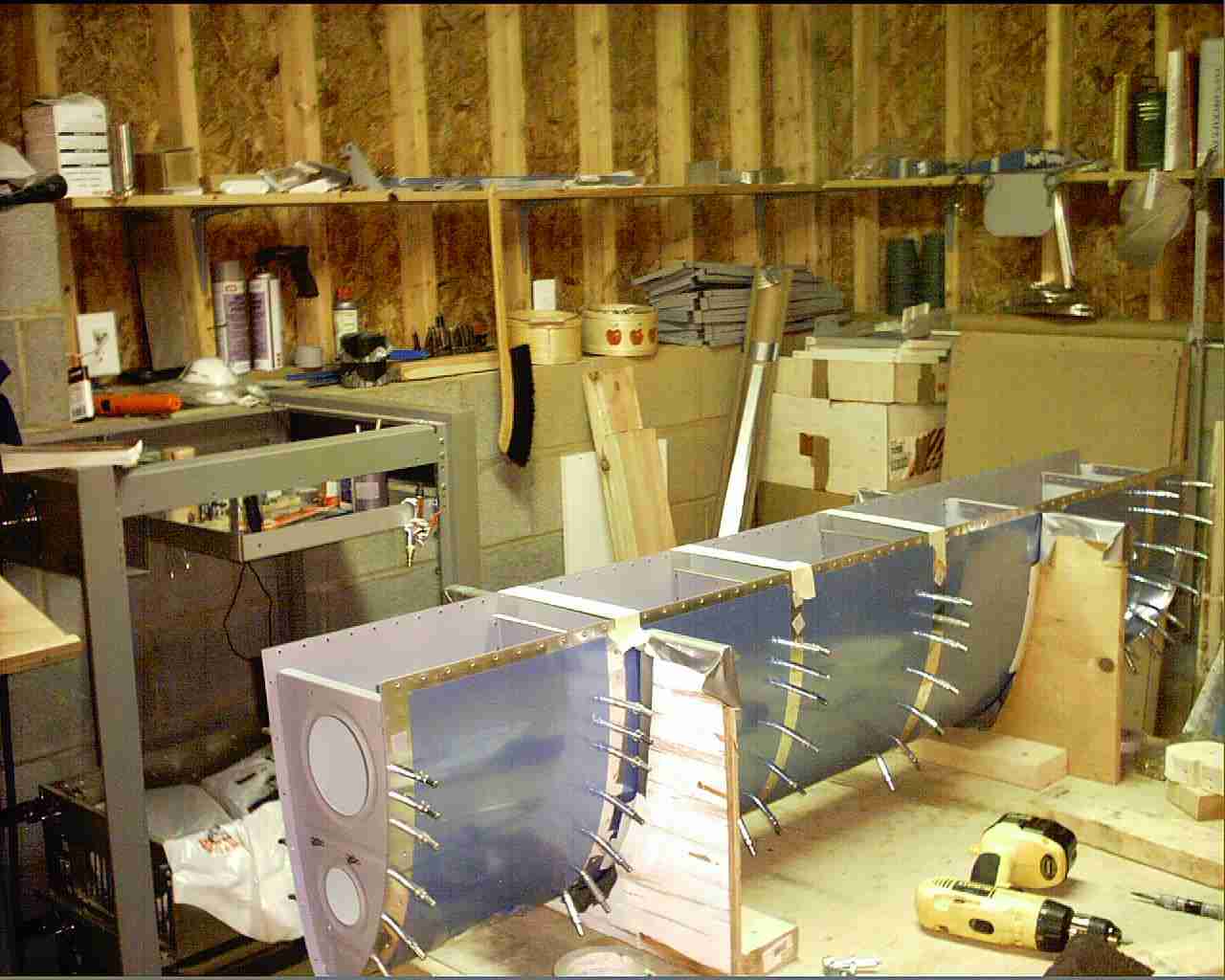
Here it the left wing off the jig for the first time.
()3/20/04) E
Here it the left wing off the jig for the first time.
()3/20/04) |
| |
 F
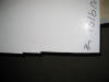
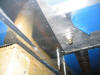
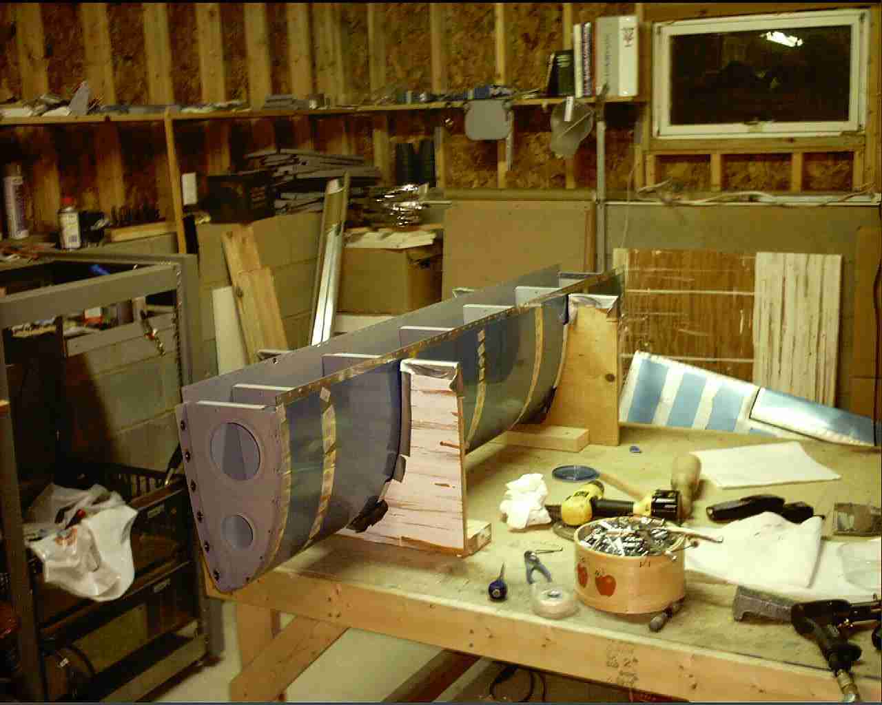
We even managed to assemble and match drill the right wing
during Doug's visit. Now all that is left is deburring,
dimpling, priming, and riveting. (03/21/04) F
We even managed to assemble and match drill the right wing
during Doug's visit. Now all that is left is deburring,
dimpling, priming, and riveting. (03/21/04) |
| |
 E
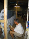
After a long delay, Nora's Father came by on 07/31/04 to help
buck rivets on the leading edge and top skins of the right
wing. (Sorry no pictures) On August 14th John
Wigney, Europa builder and now flier, came by on short notice
to help me finish riveting the top skins on the right wing.
(08/14/04) E
After a long delay, Nora's Father came by on 07/31/04 to help
buck rivets on the leading edge and top skins of the right
wing. (Sorry no pictures) On August 14th John
Wigney, Europa builder and now flier, came by on short notice
to help me finish riveting the top skins on the right wing.
(08/14/04) |
| |
 F
Four hours later John helped me lift the wing off the jig and
place it on the cradle. After John left I celebrated by
taking down the wing jig and cleaning the place up. Next
week I order the fuselage kit. (08/14/04) F
Four hours later John helped me lift the wing off the jig and
place it on the cradle. After John left I celebrated by
taking down the wing jig and cleaning the place up. Next
week I order the fuselage kit. (08/14/04) |
| |
 E
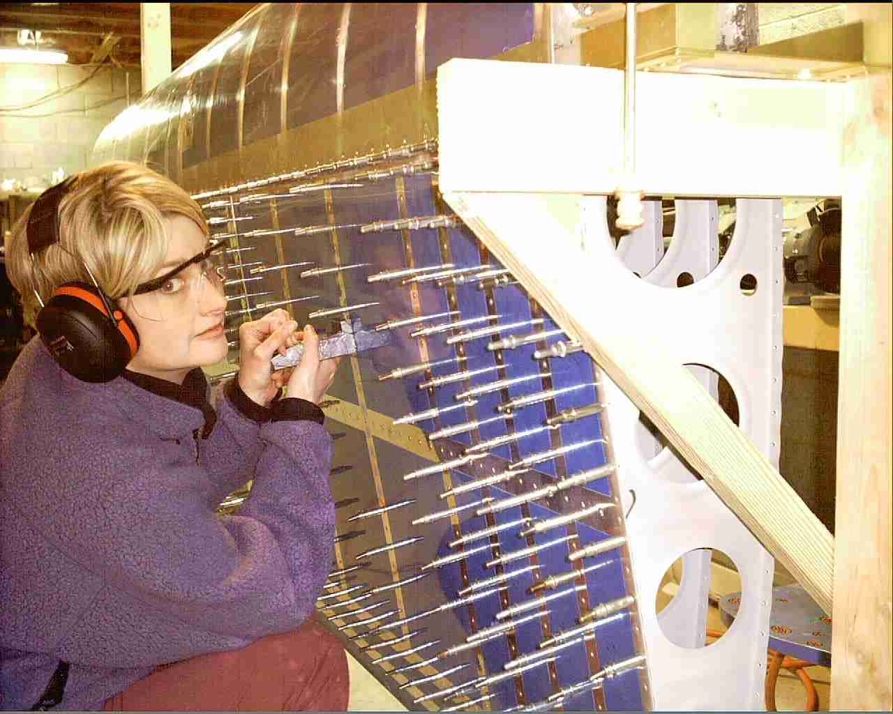
Six days before the wedding and here is Nora helping rivet the
bottom skin on the right wing. At least she can't say
she didn't know what she was getting herself into. (09/06/04) E
Six days before the wedding and here is Nora helping rivet the
bottom skin on the right wing. At least she can't say
she didn't know what she was getting herself into. (09/06/04) |
| |
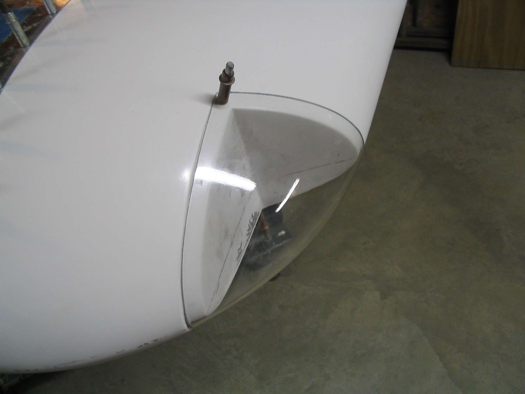
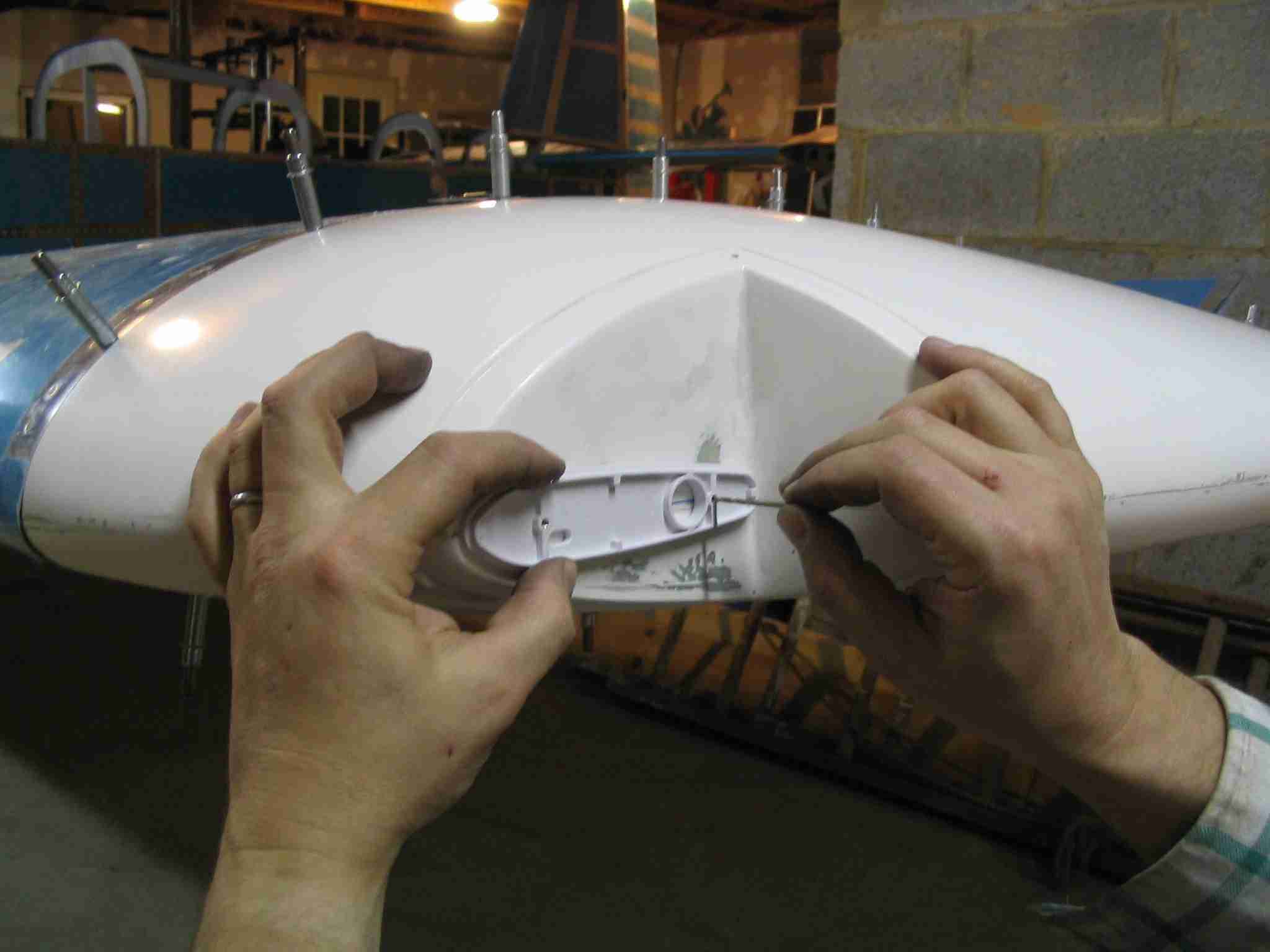
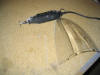
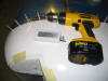
 F
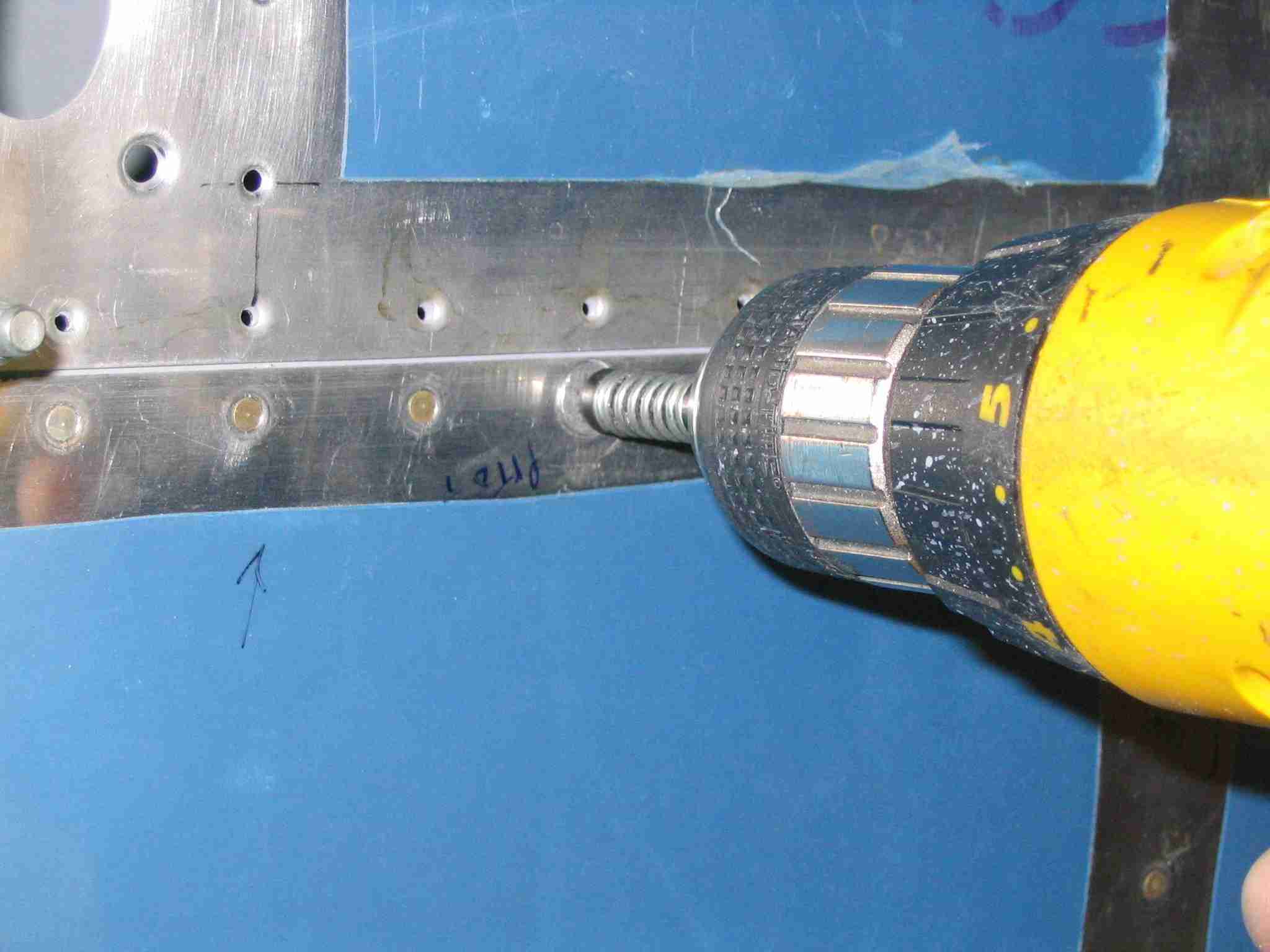
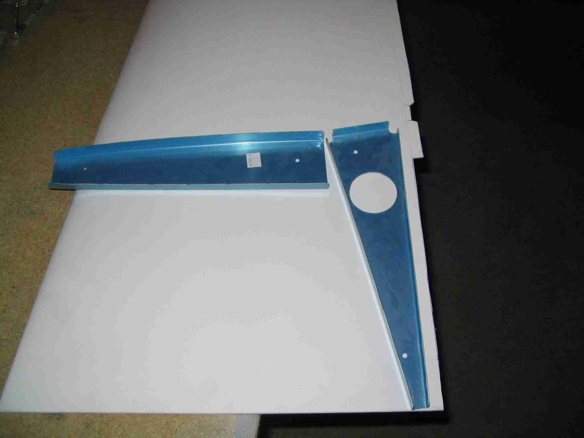
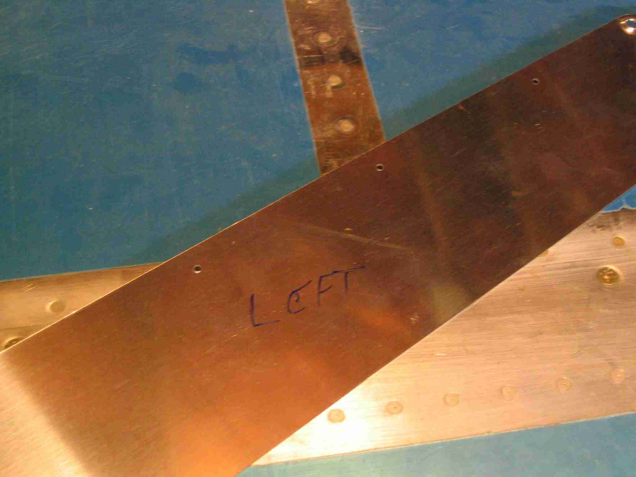
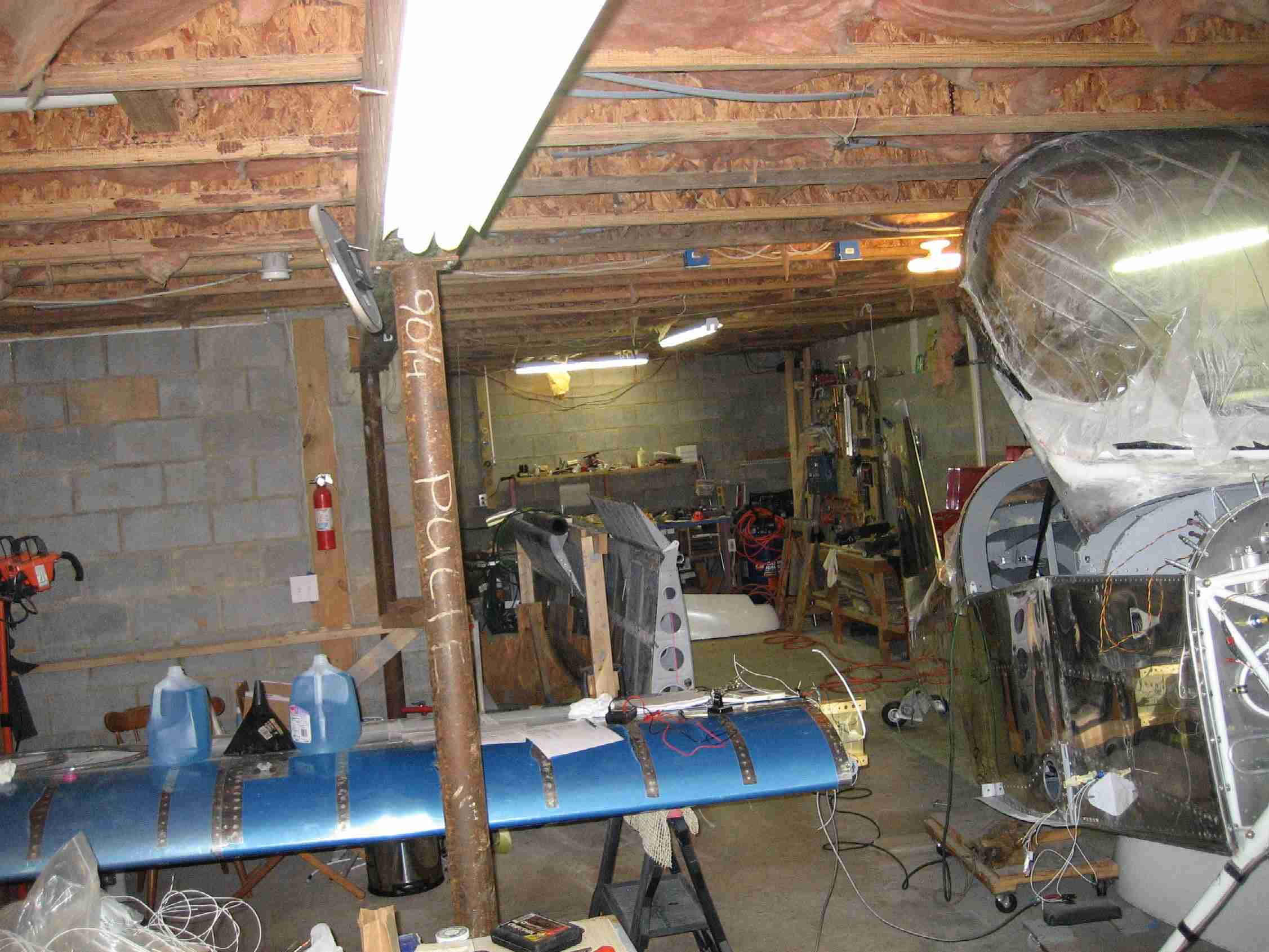
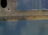
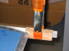
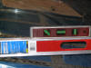
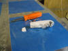
Last weekend
was spent cutting the left wing skin and fitting the Gretz
pitot tube mast, which is supposed to hold the Dynon pitot
tube. This pitot tube is configured to feed AOA information
to my future Dynon EFIS system. After cutting the wing skin,
drilling holes for the AOA line, etc. I test fitted the mast
and all looked good until I slid the pitot tube down the mast
and found the pre-drilled holes in the mast that are to hold
the pitot in place wouldn't leave any room for proper edge
distance on the pitot tube. I'm currently talking to both
Dynon and Warren Gretz about a solution. BTW, both the Gretz
mount and the Dynon unit seem to be top quality items and I do
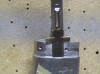
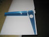
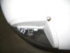
expect there will be an easy resolution. (I smudged the
chrome pitot tube bracket so the flash wouldn't wash it out
.) (09/25/04) F
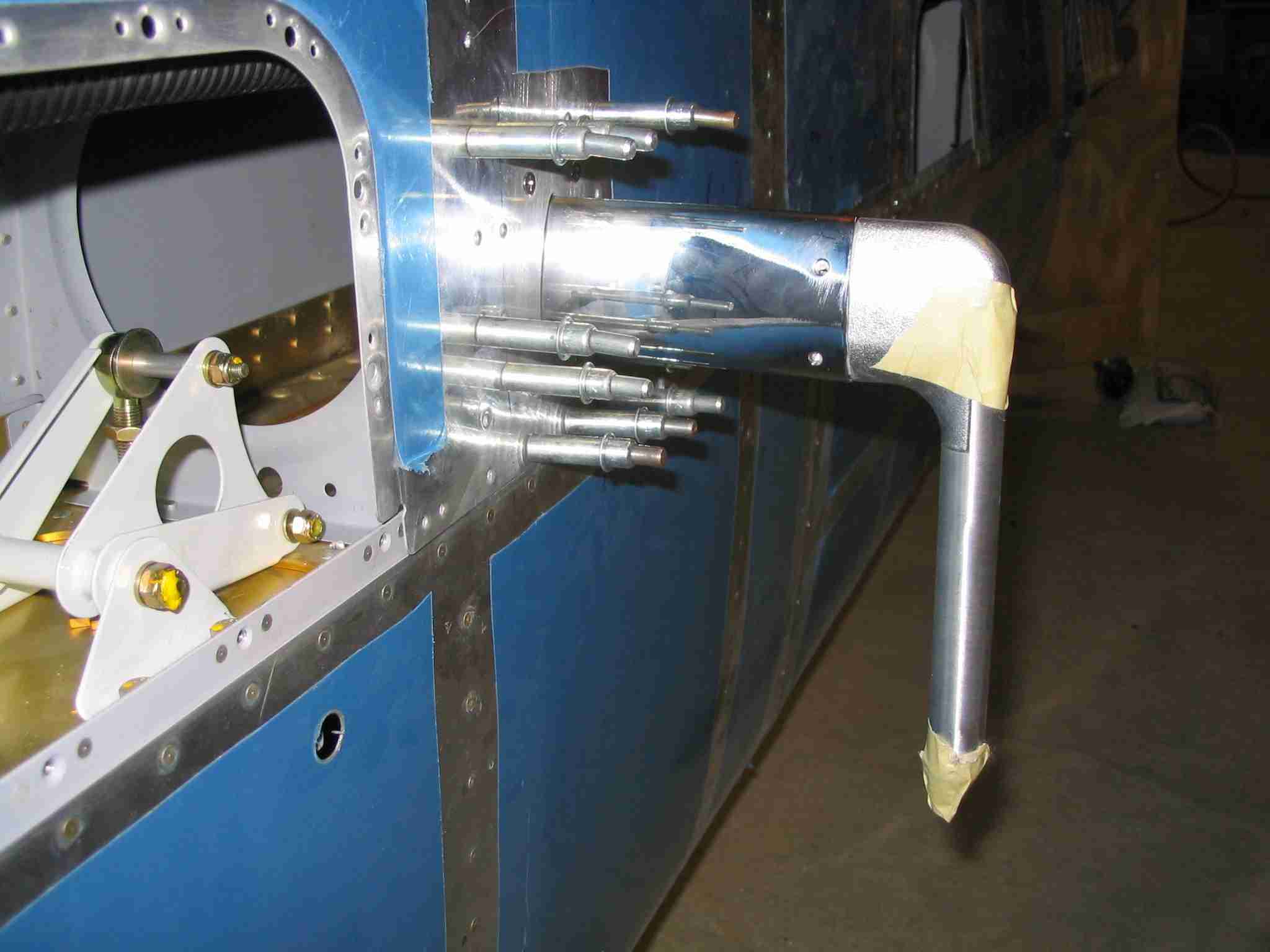
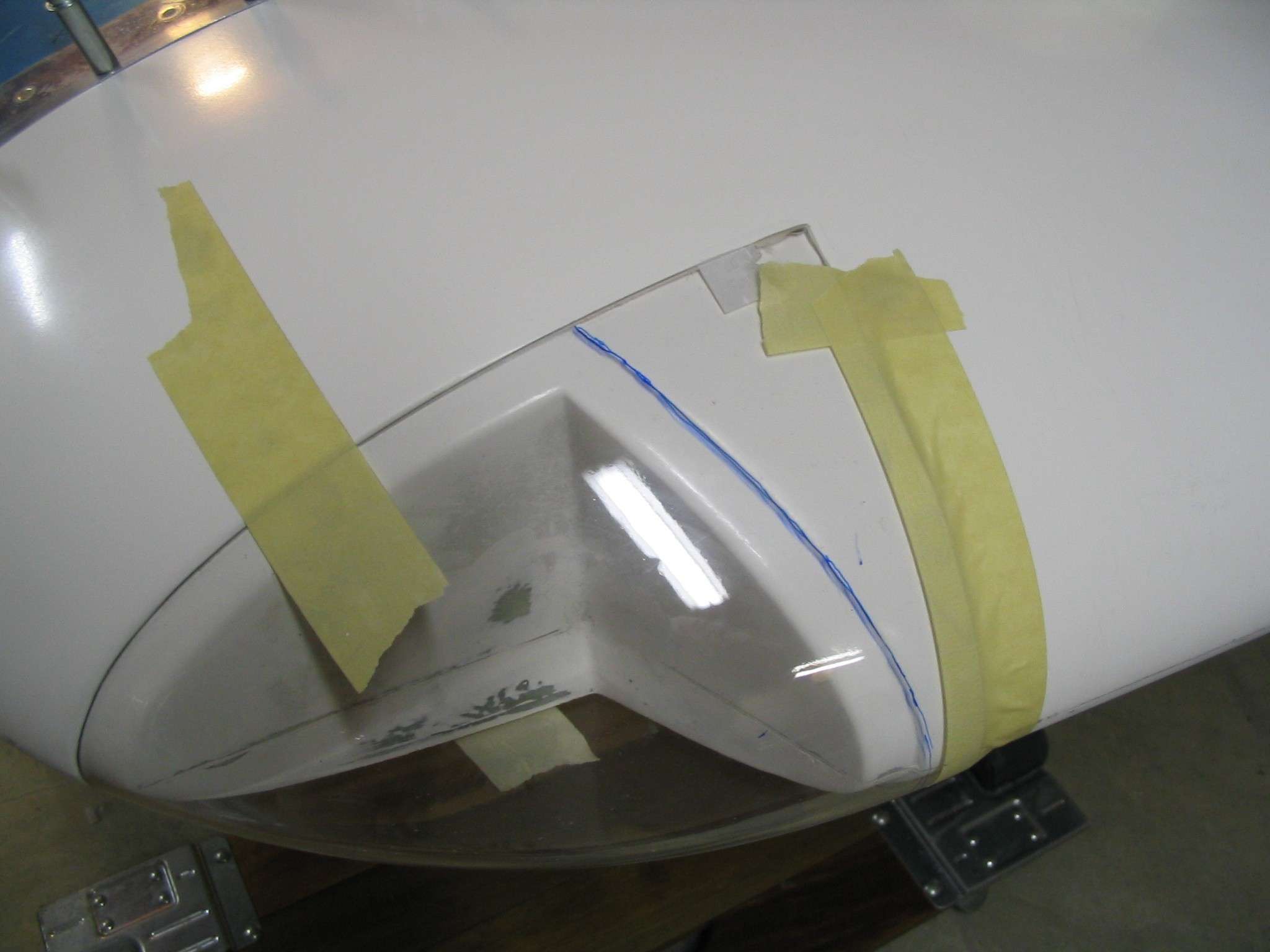
Last weekend
was spent cutting the left wing skin and fitting the Gretz
pitot tube mast, which is supposed to hold the Dynon pitot
tube. This pitot tube is configured to feed AOA information
to my future Dynon EFIS system. After cutting the wing skin,
drilling holes for the AOA line, etc. I test fitted the mast
and all looked good until I slid the pitot tube down the mast
and found the pre-drilled holes in the mast that are to hold
the pitot in place wouldn't leave any room for proper edge
distance on the pitot tube. I'm currently talking to both
Dynon and Warren Gretz about a solution. BTW, both the Gretz
mount and the Dynon unit seem to be top quality items and I do
expect there will be an easy resolution. (I smudged the
chrome pitot tube bracket so the flash wouldn't wash it out
.) (09/25/04) |
| |
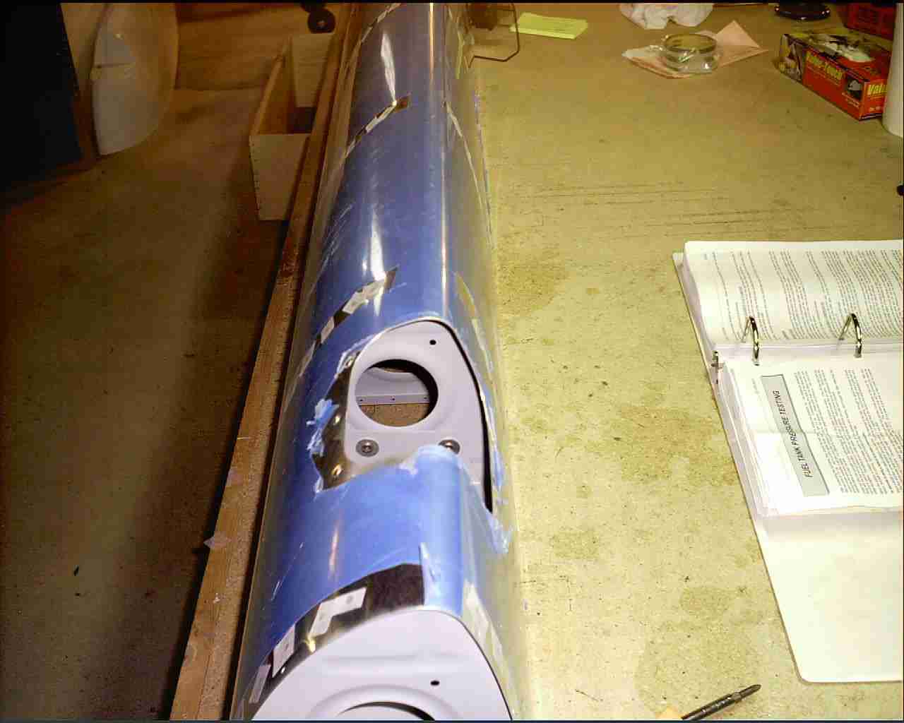
 E
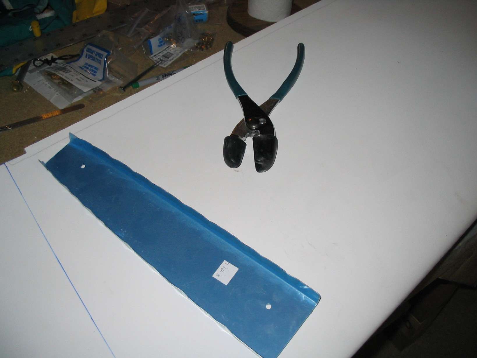
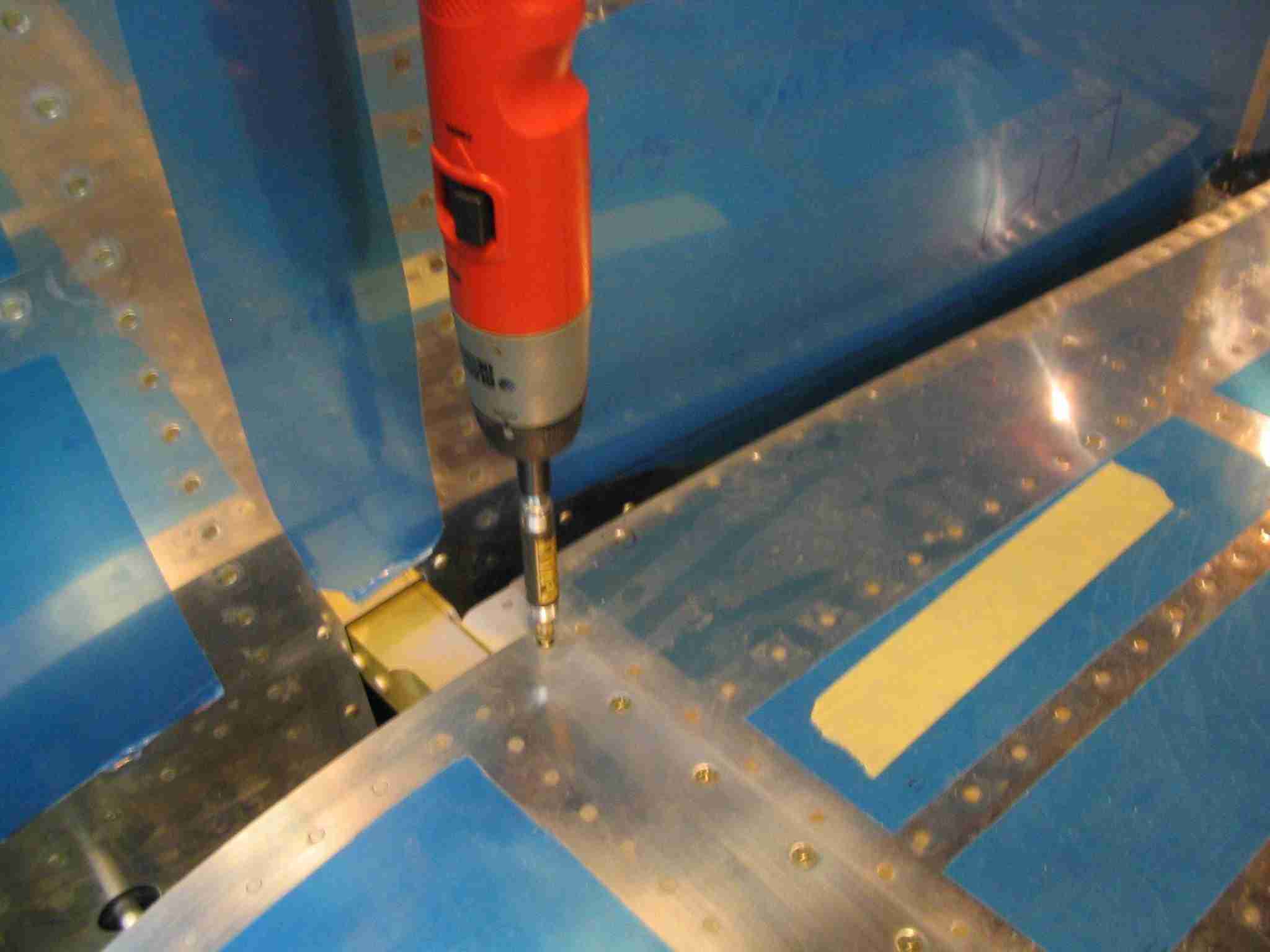
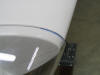
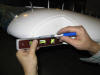
It has been a while since I've worked on the plane. Nora
and I were still wrapping up wedding commitments which has
left no time for other things. Anyway, I finally had a
chance to test fit the pitot tube. (The tape is to keep
bugs from taking up residence in the pitot system until it is
actually used.) (10/26/04) E
It has been a while since I've worked on the plane. Nora
and I were still wrapping up wedding commitments which has
left no time for other things. Anyway, I finally had a
chance to test fit the pitot tube. (The tape is to keep
bugs from taking up residence in the pitot system until it is
actually used.) (10/26/04) |
| |
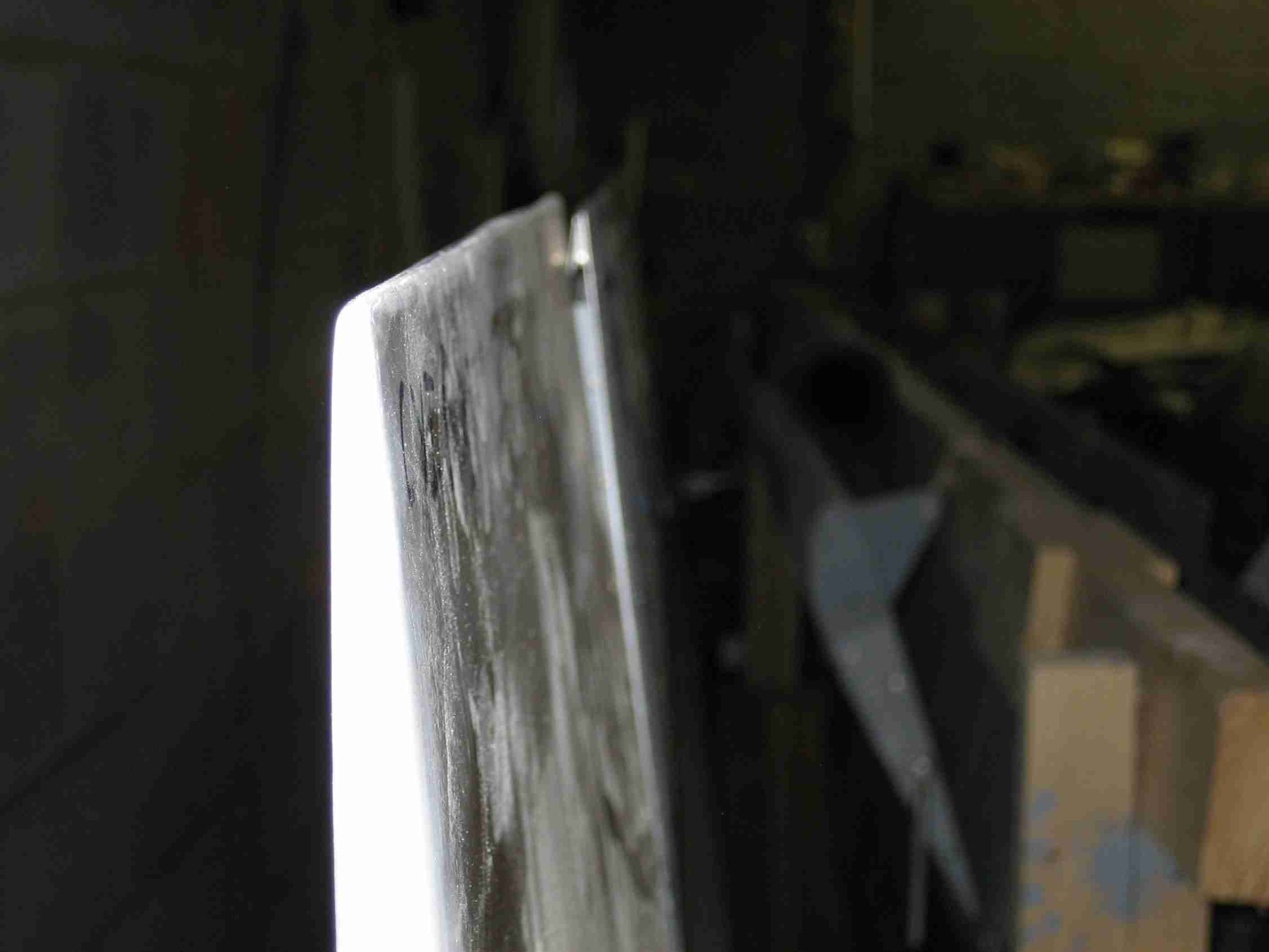
 F
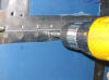
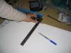
One other reason for the delay was the Dynon pitot tube had to
be modified by filing down the neck so it would fit into the
Gretz mount far enough that the #6 screws used to secure it
would have enough edge space. Some careful work on the
belt sander, followed by hand filing did the trick.
(10/26/04) F
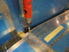
One other reason for the delay was the Dynon pitot tube had to
be modified by filing down the neck so it would fit into the
Gretz mount far enough that the #6 screws used to secure it
would have enough edge space. Some careful work on the
belt sander, followed by hand filing did the trick.
(10/26/04) |
| |
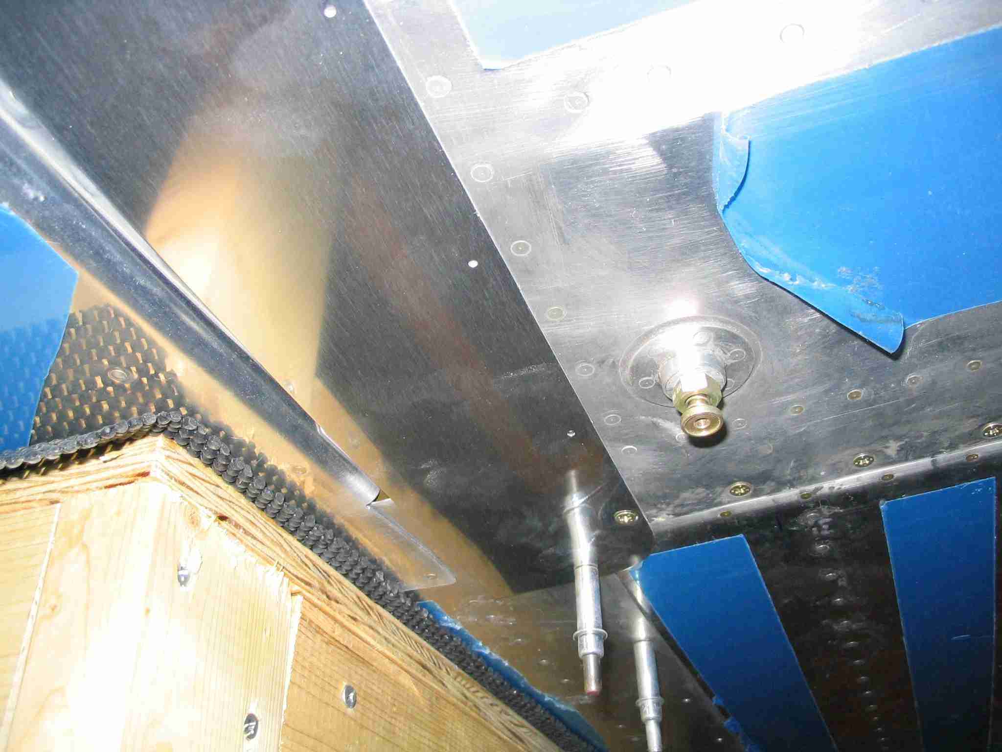
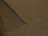
 E
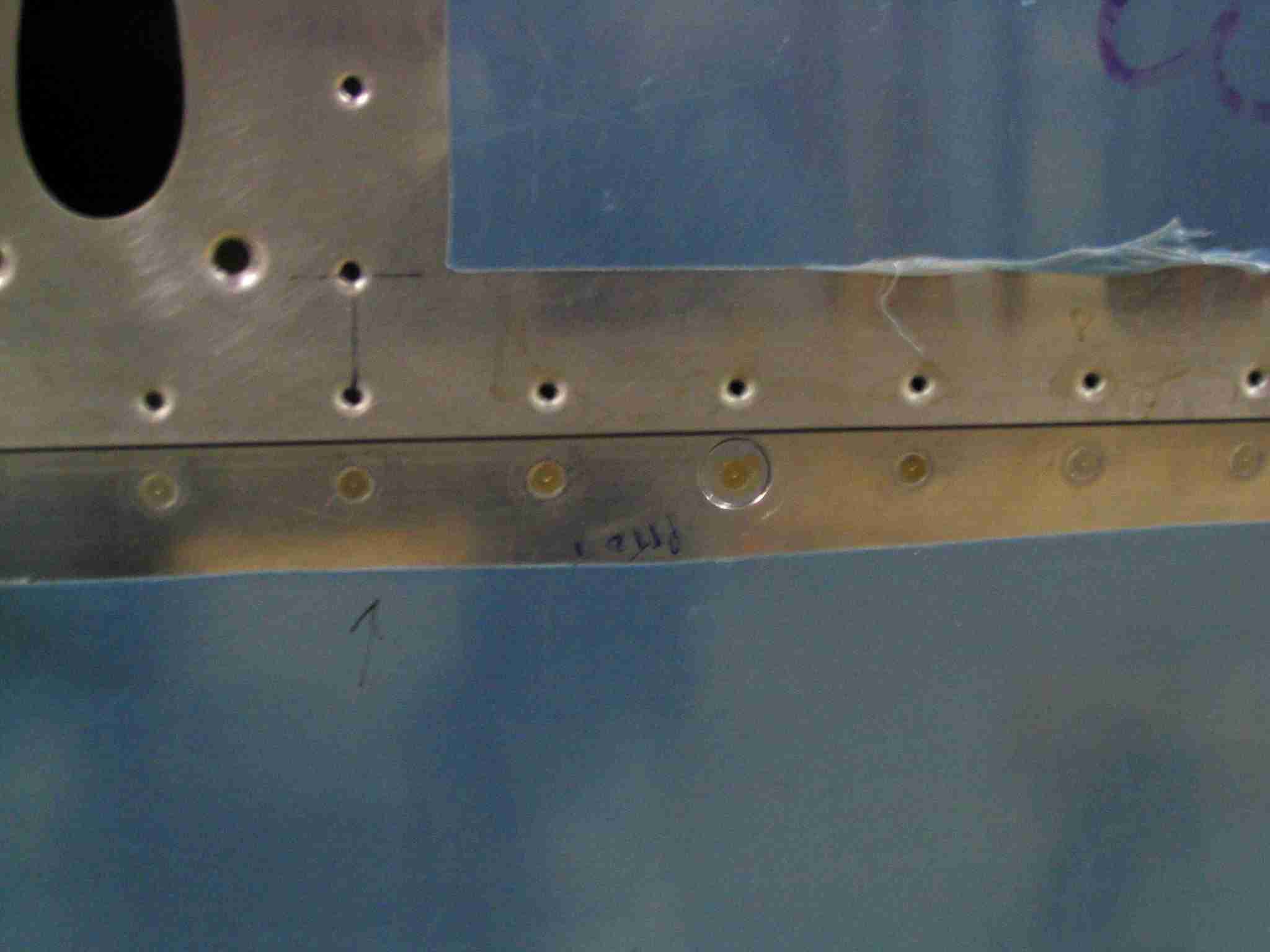
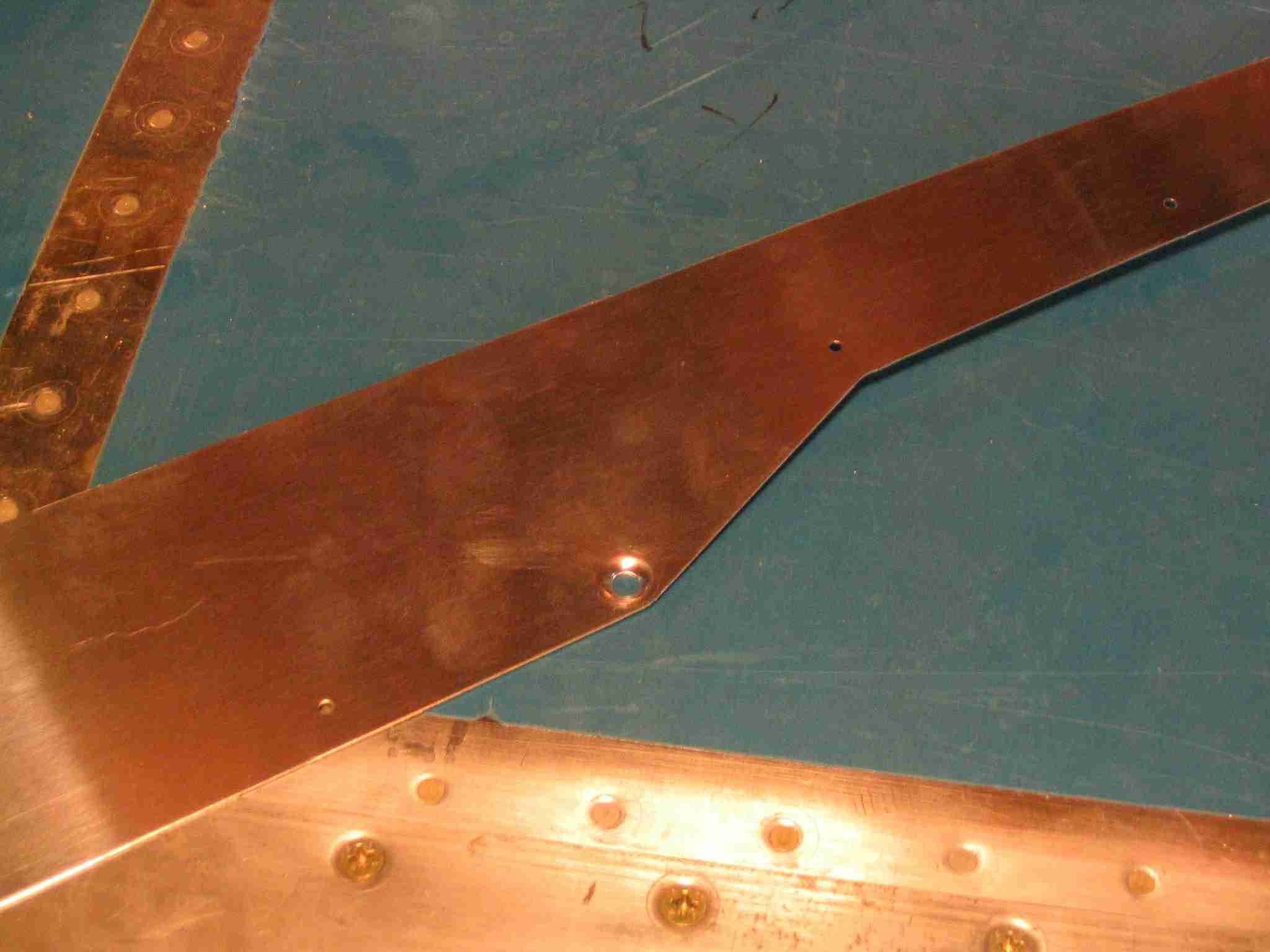
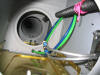
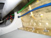
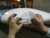
Here
is how the pitot tube and AOA lines will look inside the
wing. They will be tie-wrapped to the black wire conduit at
the top of the picture. Remember, the aileron push tube has
to go occupy this space as well as the lines. The pink string
will remain in place in case I ever wish to install a heated
pitot tube and need to pull a wire for it. E
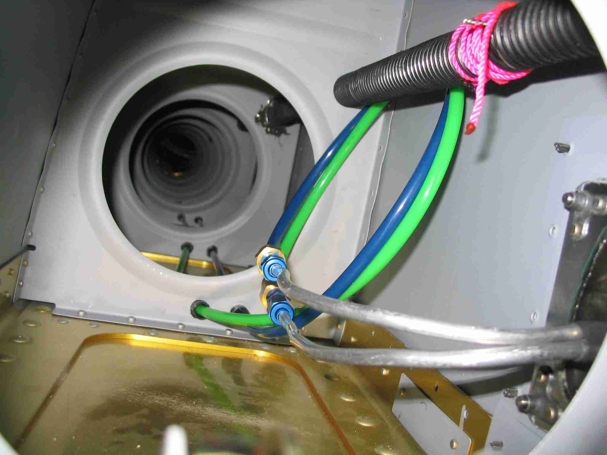
Here
is how the pitot tube and AOA lines will look inside the
wing. They will be tie-wrapped to the black wire conduit at
the top of the picture. Remember, the aileron push tube has
to go occupy this space as well as the lines. The pink string
will remain in place in case I ever wish to install a heated
pitot tube and need to pull a wire for it.
Update: July 15, 2007
 E After
installing the wings, pitot, etc. at the airport and after the
VFR transponder and pitot/static check I found the connections
above leaked like the Titanic. On the advice of the
Avionics Technician who inspected my plane, I changed the
connection by cutting off the AN fittings and removed the
quick connect. I suspect it was the "quick
connect" that leaked, not the AN fitting. They were
replaced with a section of vacuum hose and some tie wraps.
E After
installing the wings, pitot, etc. at the airport and after the
VFR transponder and pitot/static check I found the connections
above leaked like the Titanic. On the advice of the
Avionics Technician who inspected my plane, I changed the
connection by cutting off the AN fittings and removed the
quick connect. I suspect it was the "quick
connect" that leaked, not the AN fitting. They were
replaced with a section of vacuum hose and some tie wraps. |
| |
 F
Every married builder soon realizes that at some point in the
project their wonderful and understanding wife asks for a
favor. It is at that point the builder had better jump on it,
get it done, and make the wife happy so they can get back to
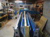
building. My little task was to finish carpeting a cat tree
that I had built some time before. The problem was where I
should store the flaps while I work on the cat tree. It
dawned on me I could build a rack on the wing cradle to hold
and protect them. (2/13/05) F
Every married builder soon realizes that at some point in the
project their wonderful and understanding wife asks for a
favor. It is at that point the builder had better jump on it,
get it done, and make the wife happy so they can get back to
building. My little task was to finish carpeting a cat tree
that I had built some time before. The problem was where I
should store the flaps while I work on the cat tree. It
dawned on me I could build a rack on the wing cradle to hold
and protect them. (2/13/05) |
| |
 E
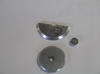
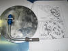
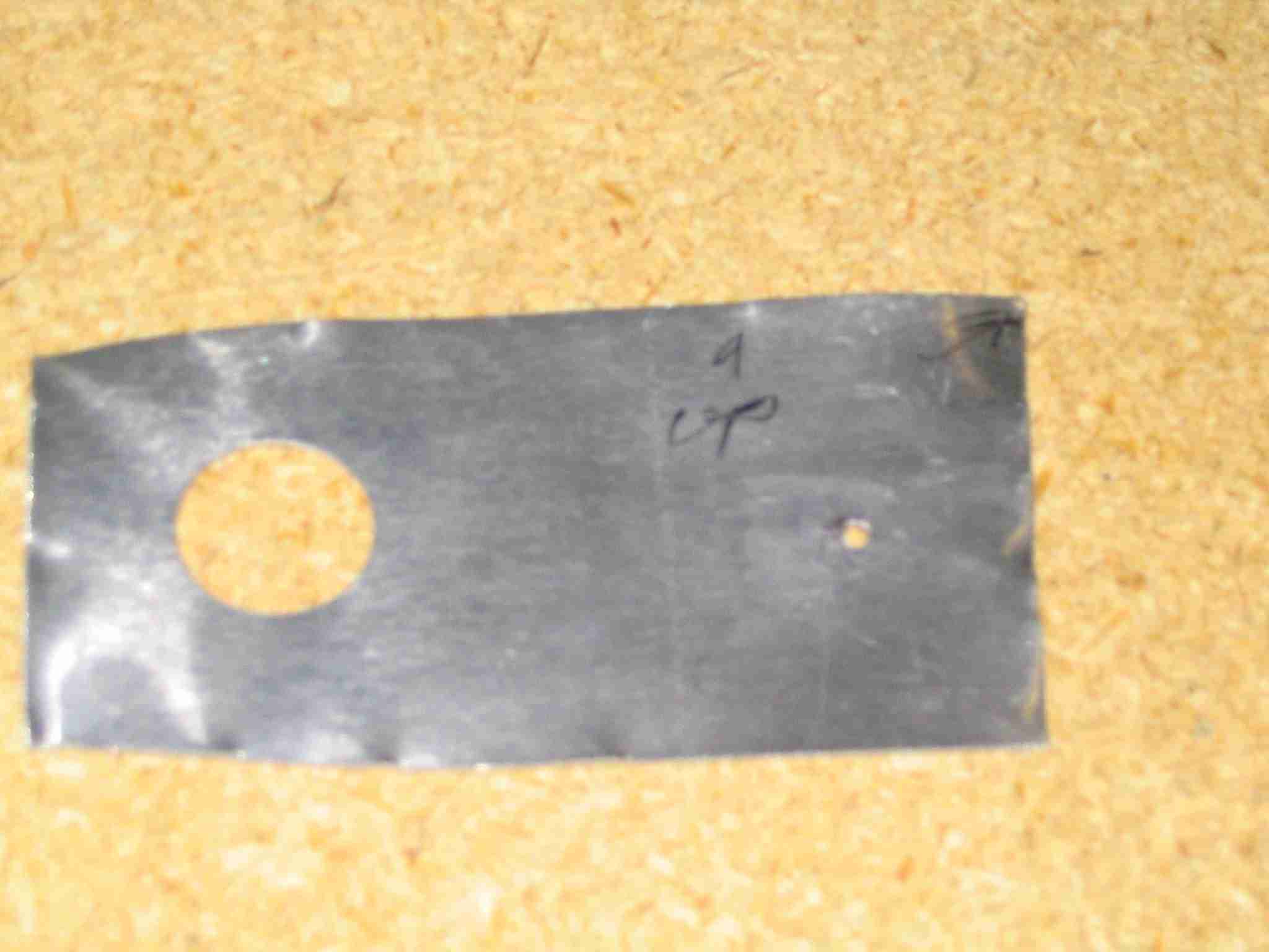
I finally got around to plugging the hole I drilled in the
bottom of the left wing for Van's pitot tube. I drew a
circle on scrape aluminum I had laying around, in my case it
was the disks I cut out of the VS stiffener for the lightening
holes. After drilling a center hole and countersinking
it for the rivet I cut, sanded, and filed the plug until it
fit in the hole. The rivets on either side of the pitot
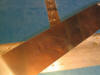
tube hole were drilled out and a strap made from some scrap
064 aluminum was cut to bridge the three holes. The
strap was riveted in place leaving a pocket where the pitot
tube was supposed to go. E
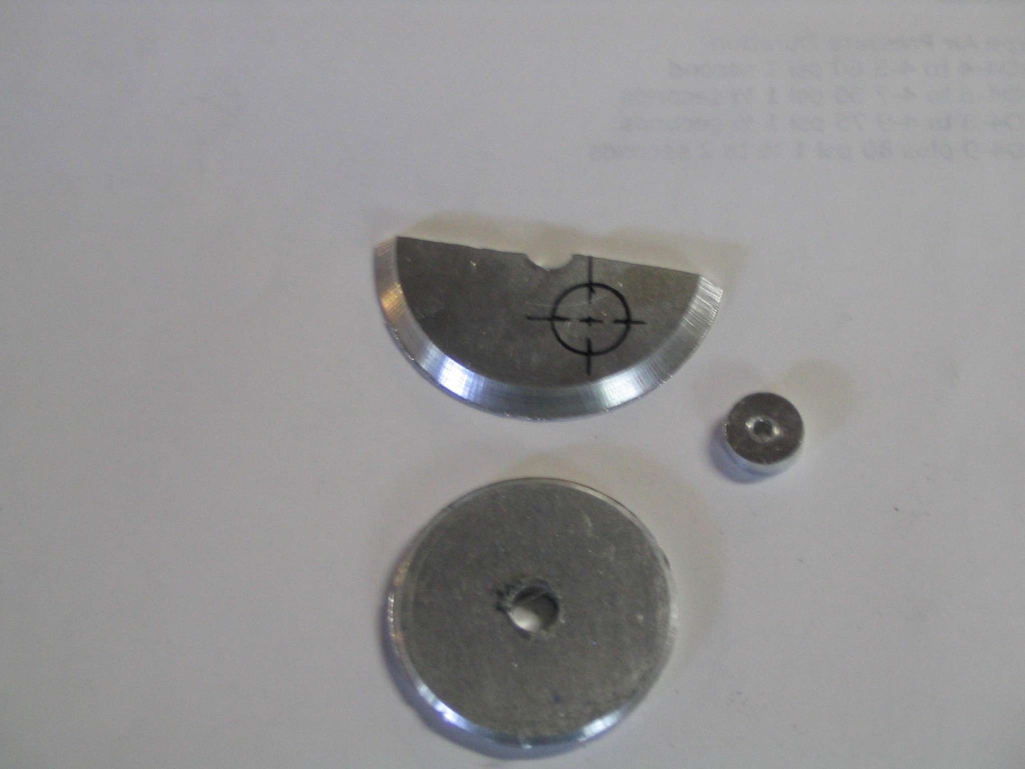
I finally got around to plugging the hole I drilled in the
bottom of the left wing for Van's pitot tube. I drew a
circle on scrape aluminum I had laying around, in my case it
was the disks I cut out of the VS stiffener for the lightening
holes. After drilling a center hole and countersinking
it for the rivet I cut, sanded, and filed the plug until it
fit in the hole. The rivets on either side of the pitot
tube hole were drilled out and a strap made from some scrap
064 aluminum was cut to bridge the three holes. The
strap was riveted in place leaving a pocket where the pitot
tube was supposed to go.
 E
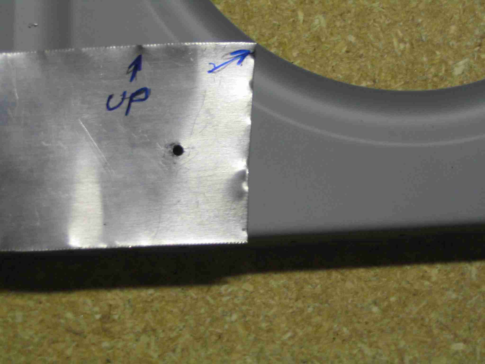
The plug was put in the hole and matched drilled to the newly
installed strap and riveted in place. E
The plug was put in the hole and matched drilled to the newly
installed strap and riveted in place.
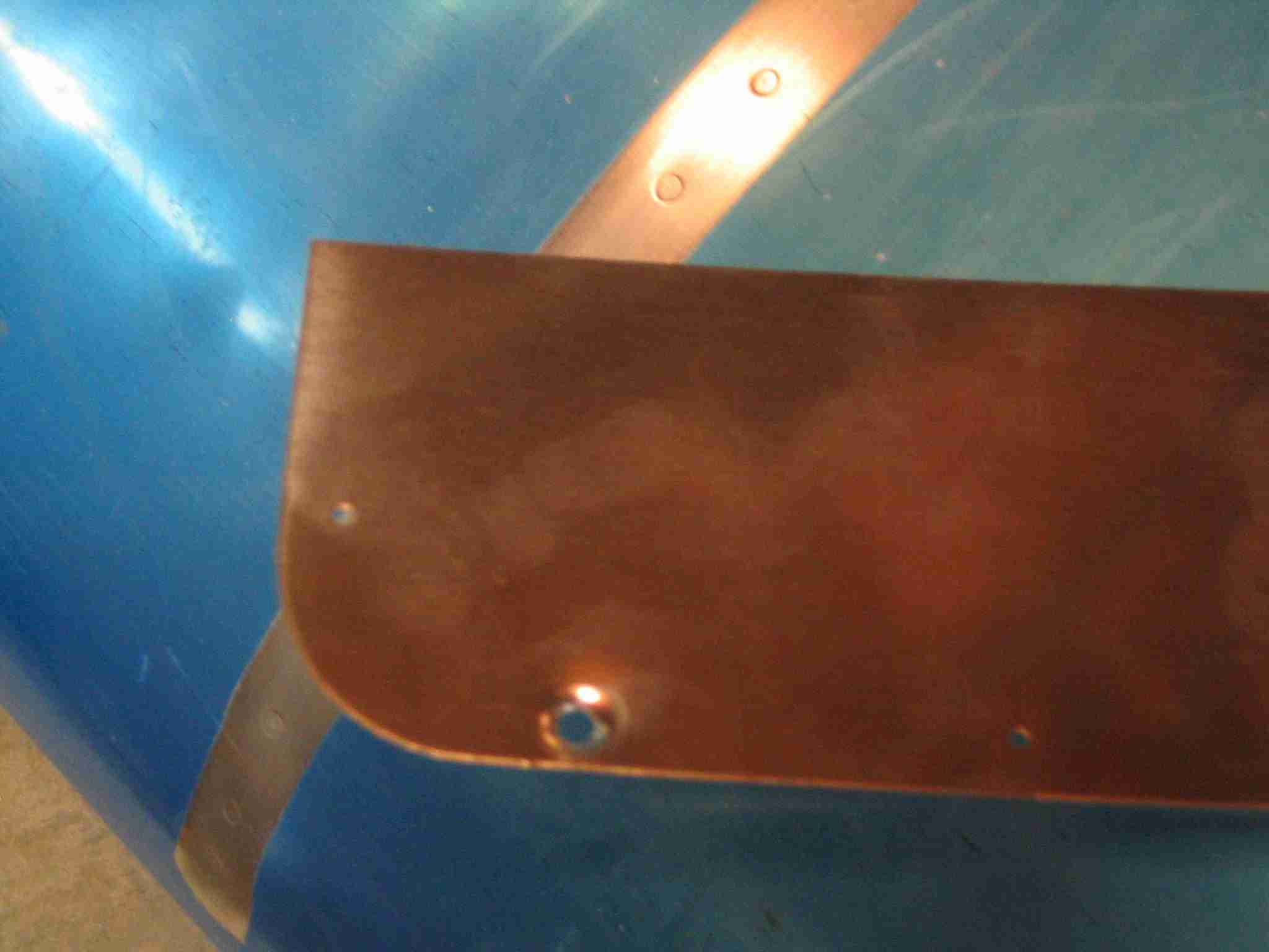
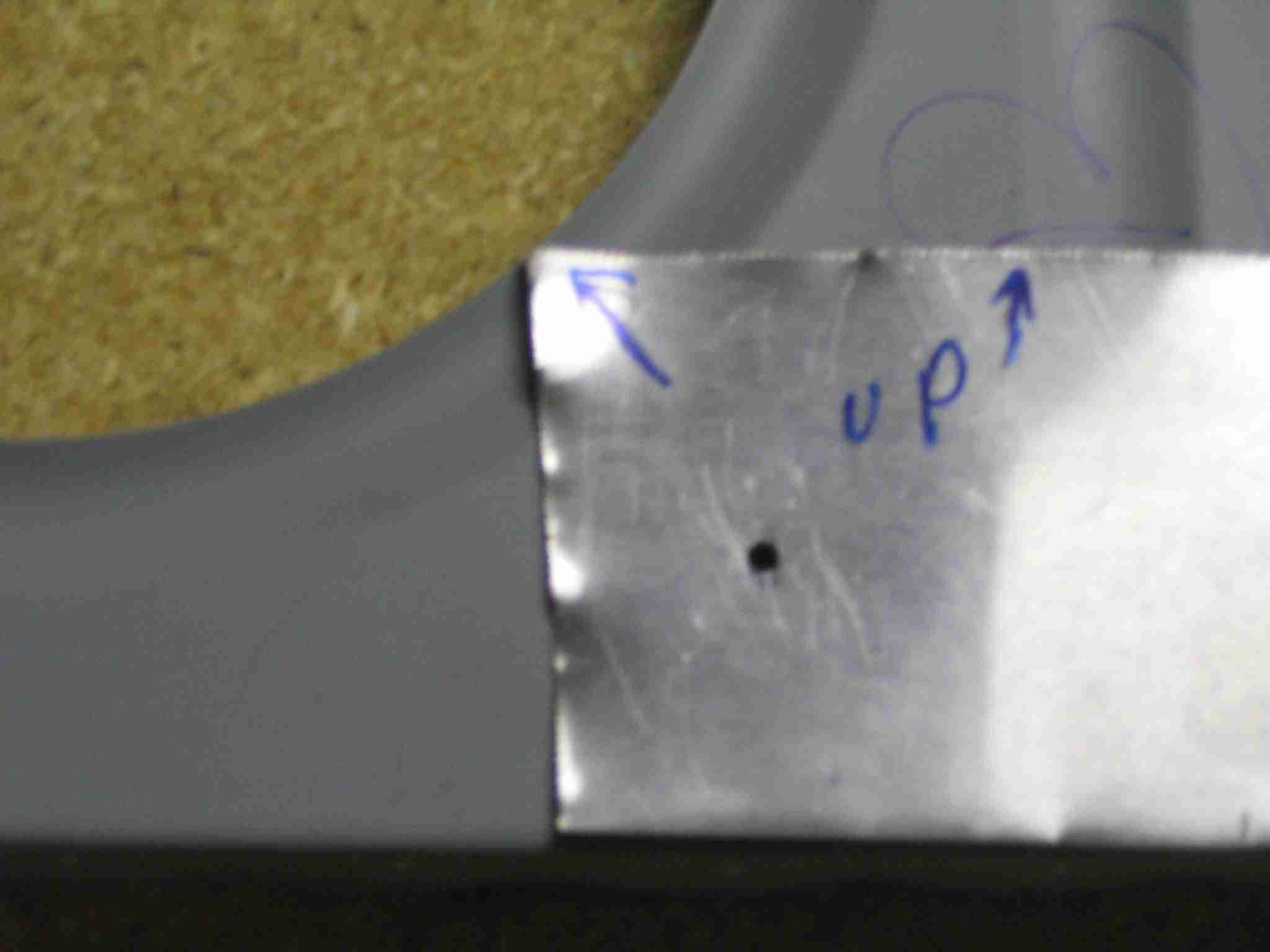
E Here is the finished
product. Not too bad but I sure wish I knew I was going to
use the Dynon pitot before I followed the instructions and
drilled out that hole (4/14/05) |
| |
 F
My in-laws came and spent Labor day weekend with us and
between going to the fantastic NC Zoo and other obligations we
managed to find time to rivet the bottom skin on the left
wing. The pitot tube is ready to install but was left
off to keep it from getting damaged. (9/4/05) F
My in-laws came and spent Labor day weekend with us and
between going to the fantastic NC Zoo and other obligations we
managed to find time to rivet the bottom skin on the left
wing. The pitot tube is ready to install but was left
off to keep it from getting damaged. (9/4/05) |
| |
  E
Fitting the wing tips isn't that difficult. The trick is
to measure the recesses and cut them to fit. The
dimensions are listed on one of the drawings and I'm too lazy
to walk back to the basement to find out which drawing.
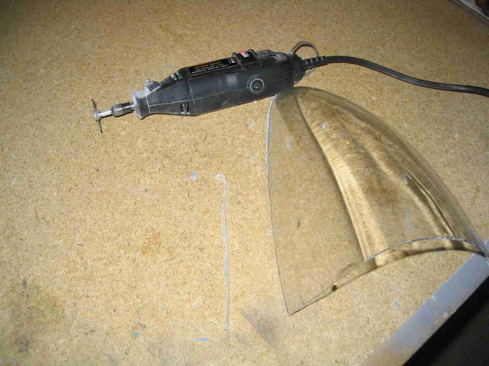
I used a cutoff wheel in my Dremel and it worked great.
I'm sure there are other ways to cut the fiberglass but this
method was recommended to me and it worked. (11/15/05) E
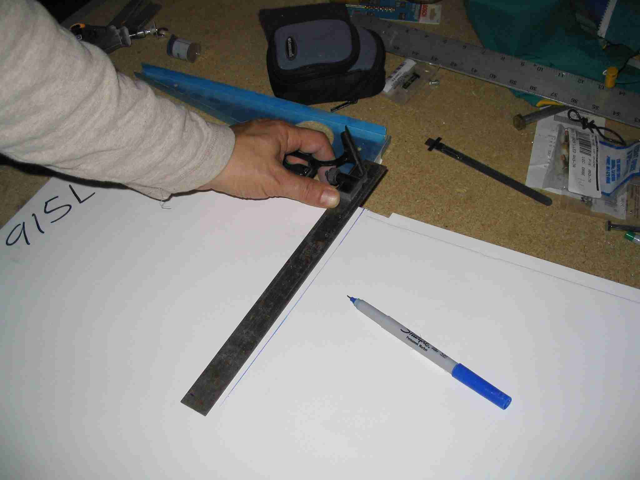
Fitting the wing tips isn't that difficult. The trick is
to measure the recesses and cut them to fit. The
dimensions are listed on one of the drawings and I'm too lazy
to walk back to the basement to find out which drawing.
I used a cutoff wheel in my Dremel and it worked great.
I'm sure there are other ways to cut the fiberglass but this
method was recommended to me and it worked. (11/15/05) |
| |
  F
Next up was fitting the the wing tip ribs. Don't forget
the to flute them. (11/15/05) F
Next up was fitting the the wing tip ribs. Don't forget
the to flute them. (11/15/05) |
| |
  E
After you figured out the correct location for the ribs, mark
the rivet lines on the wing tips, measure and drill the rivet
holes. I did this in a two step process, similar to
drilling the "J" channels. First I drilled the holes,
then marked the center of the rib flanges, lined them up and
drilled them, clecoing as I went along. (11/15/05) E
After you figured out the correct location for the ribs, mark
the rivet lines on the wing tips, measure and drill the rivet
holes. I did this in a two step process, similar to
drilling the "J" channels. First I drilled the holes,
then marked the center of the rib flanges, lined them up and
drilled them, clecoing as I went along. (11/15/05) |
| |
  F
The final step was to set the aileron to the correct position.
Remember the aileron alignment tool you made last year?
Time to dust it off. After aligning the aileron I used a
spring clamp between the aileron and the flap to hold it in
place. Since my flaps are in perfect alignment yet they
had to be lowered to match up with the aileron. With the
aileron locked in place, I lined up the wing tip, taped it in
place, and drilled it to the wing. (11/15/05) F
The final step was to set the aileron to the correct position.
Remember the aileron alignment tool you made last year?
Time to dust it off. After aligning the aileron I used a
spring clamp between the aileron and the flap to hold it in
place. Since my flaps are in perfect alignment yet they
had to be lowered to match up with the aileron. With the
aileron locked in place, I lined up the wing tip, taped it in
place, and drilled it to the wing. (11/15/05) |
| |
 E
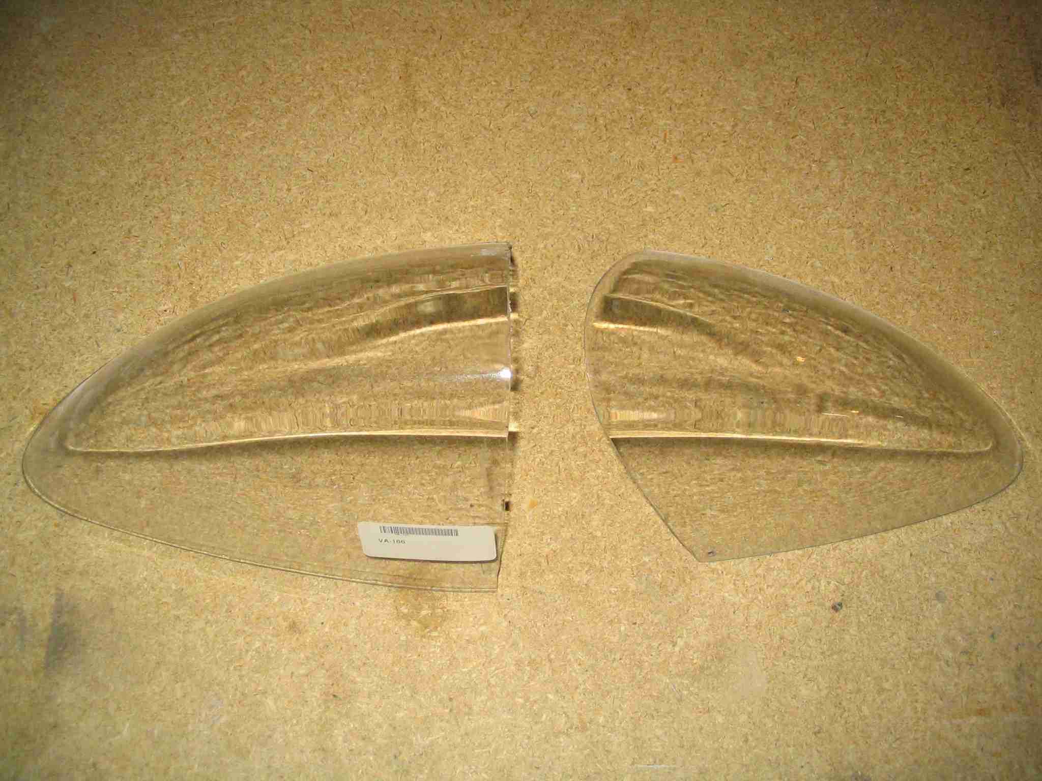
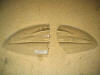
Fitting the lens covers is easy enough, even if a bit time
consuming. They come as one unit and need to be cut in
half. There are some dimples from the molding process.
Just connect the dots and cut along the line. There is
enough extra that will still require trimming you don't have
to worry about the this cut. (11/23/05) E
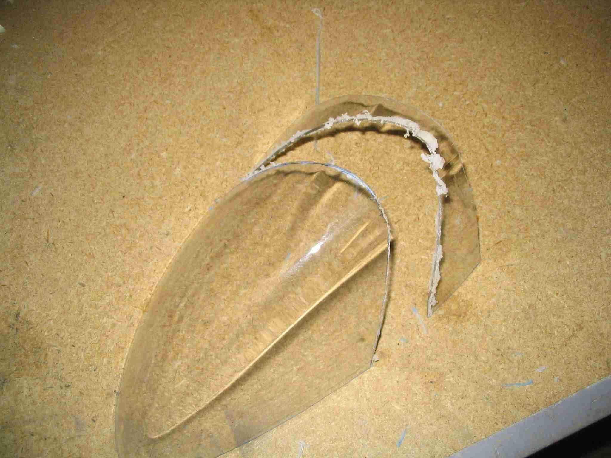
Fitting the lens covers is easy enough, even if a bit time
consuming. They come as one unit and need to be cut in
half. There are some dimples from the molding process.
Just connect the dots and cut along the line. There is
enough extra that will still require trimming you don't have
to worry about the this cut. (11/23/05) |
| |
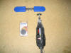 F
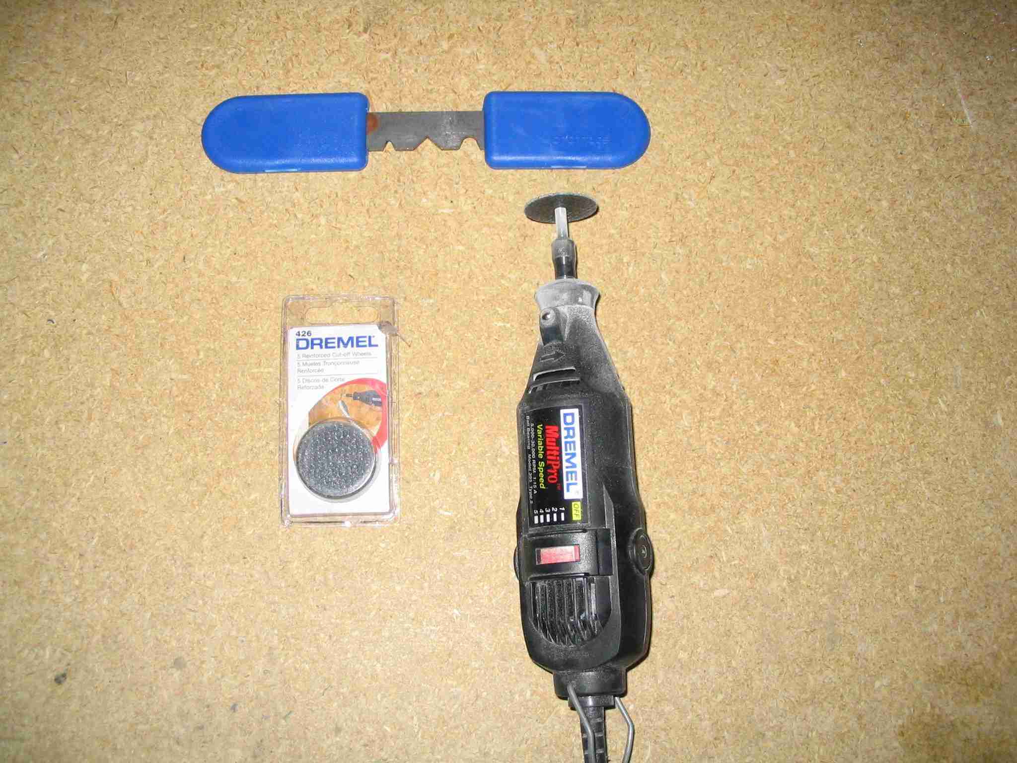
I used my Dremel with 426 reinforced cutoff wheels to cut the
fiberglass wing tips and the lens covers. Do not use
regular cutoff Dremel cutoff wheels, they tend to break off
the arbor and go shooting across your shop. I was lucky
and was never hit by one of those flying wheels. (11/23/05) F
I used my Dremel with 426 reinforced cutoff wheels to cut the
fiberglass wing tips and the lens covers. Do not use
regular cutoff Dremel cutoff wheels, they tend to break off
the arbor and go shooting across your shop. I was lucky
and was never hit by one of those flying wheels. (11/23/05) |
| |
 E
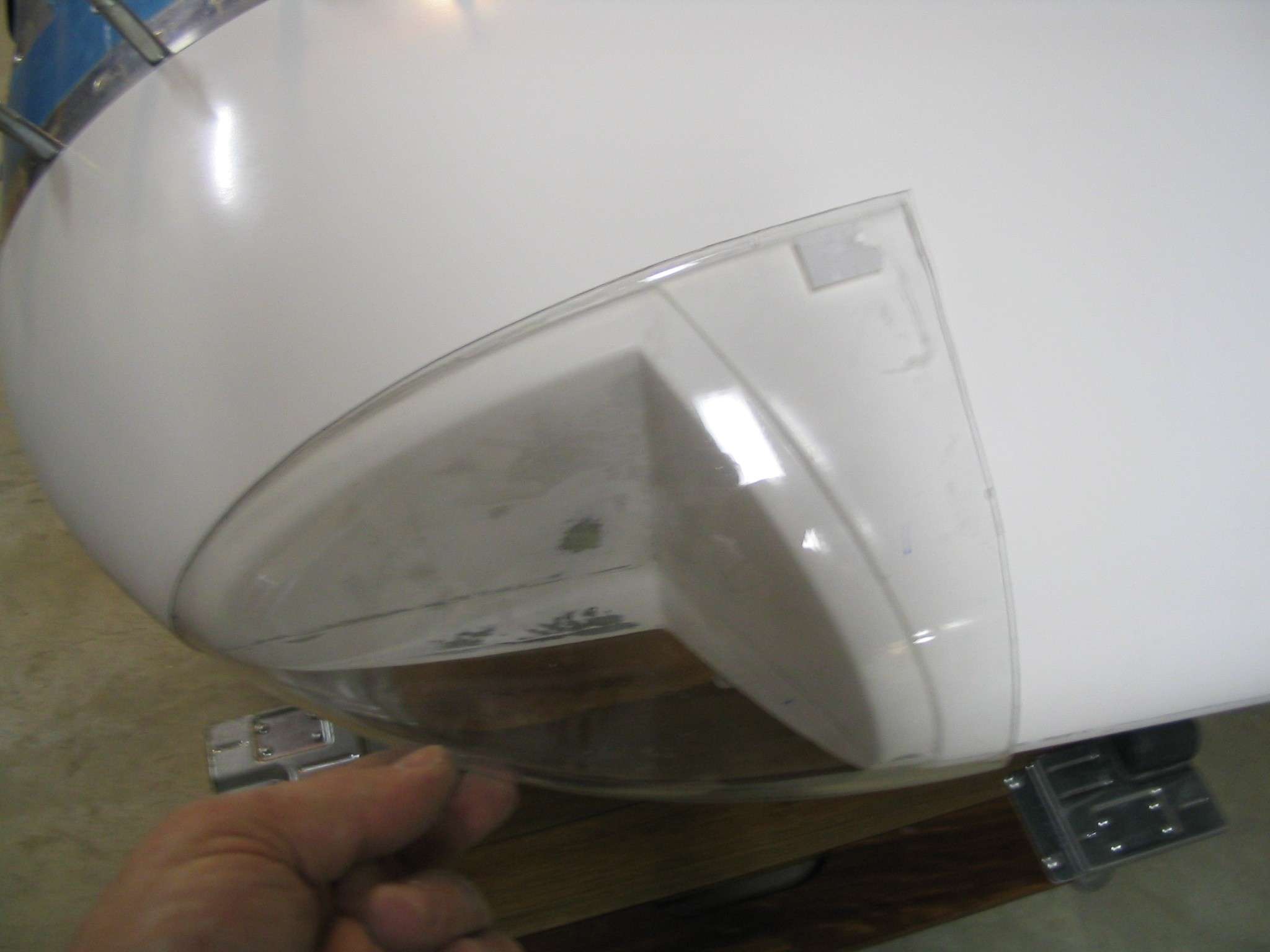
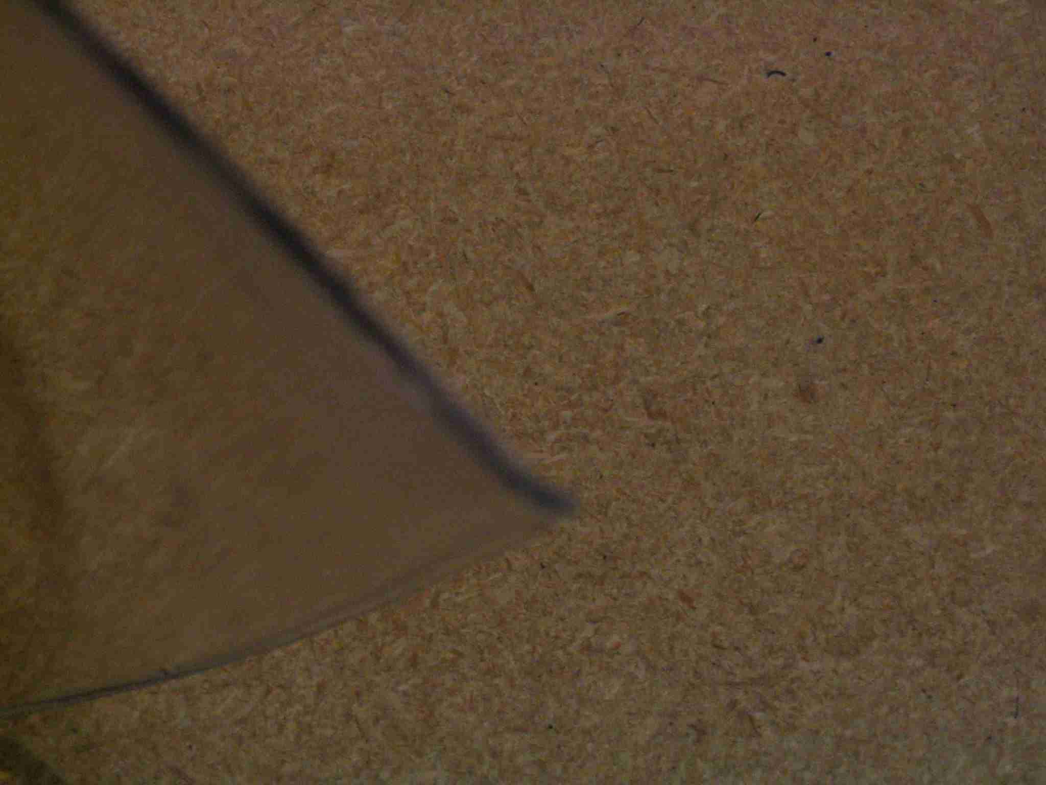
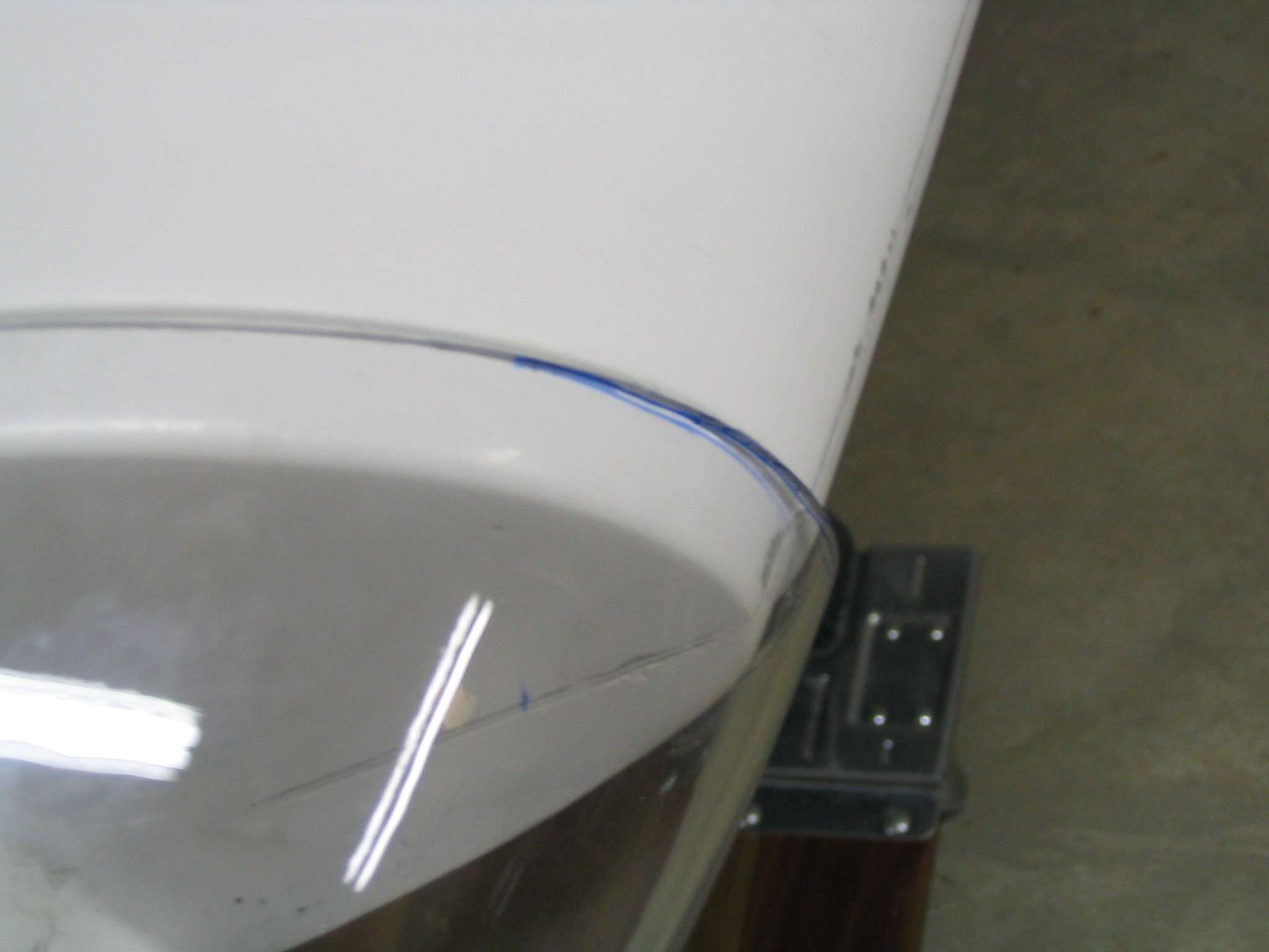
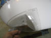
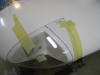
Here is the first trial fit of the lens cover, as you can see,
there is a good bit to trim. (11/23/05) E
Here is the first trial fit of the lens cover, as you can see,
there is a good bit to trim. (11/23/05) |
| |
  F
The lens has a small lip as result of the molding process.
This needs to be trimmed. Be careful not to slip with
the Dremel or you will be buying a new lens. (11/23/05) F
The lens has a small lip as result of the molding process.
This needs to be trimmed. Be careful not to slip with
the Dremel or you will be buying a new lens. (11/23/05) |
| |
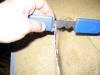  E
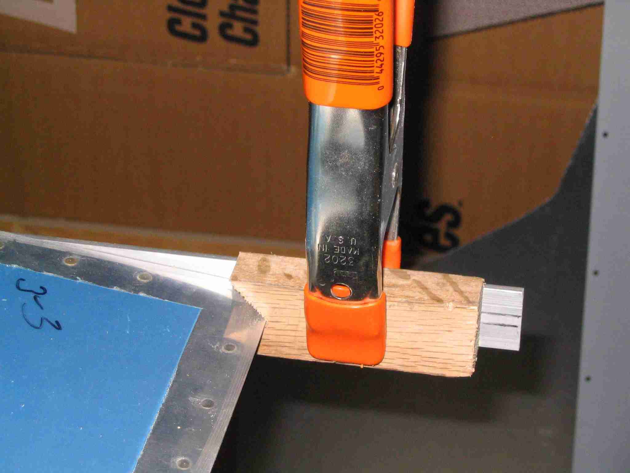
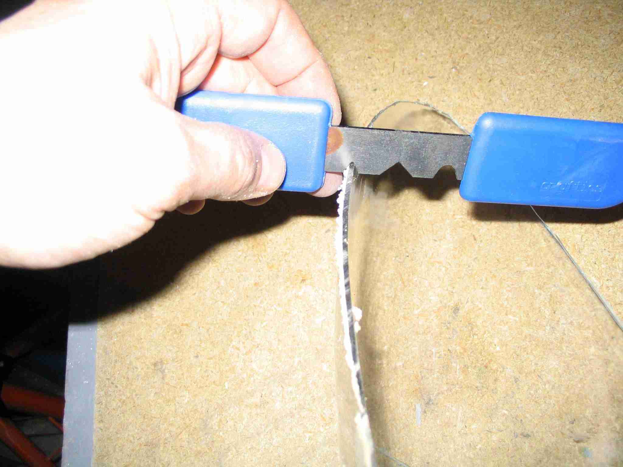
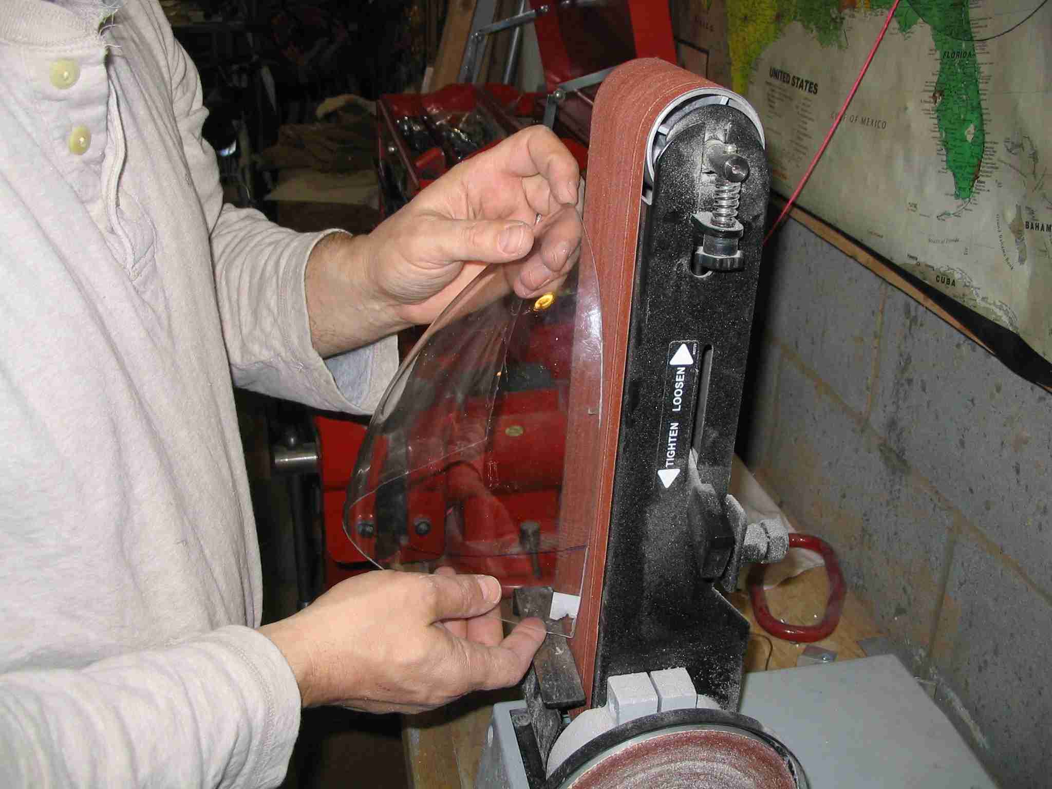
After cutting the lens the edge has to be "dressed" to keep it
from cracking. The scraper in the left most picture is
from Avery's and works well for removing the bigger "boogers"
left over from trimming. I used 120 grit sandpaper in
the belt sander and used this to finish "dress" the Plexiglas
lens. (11/23/05) E
After cutting the lens the edge has to be "dressed" to keep it
from cracking. The scraper in the left most picture is
from Avery's and works well for removing the bigger "boogers"
left over from trimming. I used 120 grit sandpaper in
the belt sander and used this to finish "dress" the Plexiglas
lens. (11/23/05) |
| |
 F
After trimming, tape the cover in place and mark it for final
trimming. You might have to repeat this process a few
times until you get a "perfect" (good enough?) fit. (11/23/05) F
After trimming, tape the cover in place and mark it for final
trimming. You might have to repeat this process a few
times until you get a "perfect" (good enough?) fit. (11/23/05) |
| |
 E
After trimming, tape the cover in place and mark it for final
trimming. You might have to repeat this process a few
times until you get a "perfect" (good enough?) fit. (11/23/05) E
After trimming, tape the cover in place and mark it for final
trimming. You might have to repeat this process a few
times until you get a "perfect" (good enough?) fit. (11/23/05) |
| |
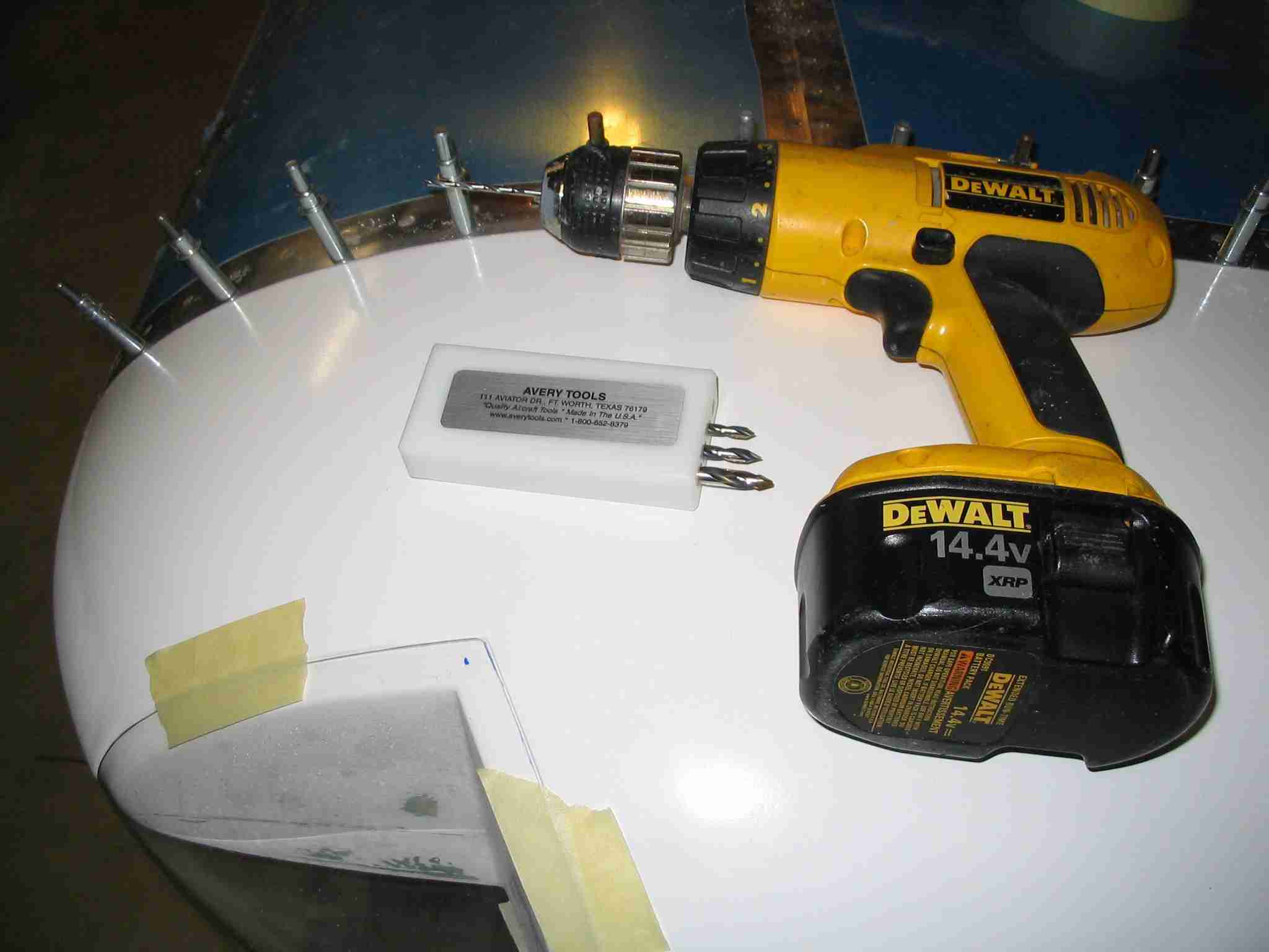
 F
Once the lens is properly fitted, tape it in place, mark the
location for the screw and drill a hole on the top and one on
the bottom. Make sure you use drill bits designed for
Plexiglas. (11/23/05) F
Once the lens is properly fitted, tape it in place, mark the
location for the screw and drill a hole on the top and one on
the bottom. Make sure you use drill bits designed for
Plexiglas. (11/23/05) |
| |
 E
Once drilled, the lens may be clecoed in place. Next up
will be countersinking the holes for machine screws and
installing the platenuts in the wing tip. (11/23/05) E
Once drilled, the lens may be clecoed in place. Next up
will be countersinking the holes for machine screws and
installing the platenuts in the wing tip. (11/23/05) |
| |
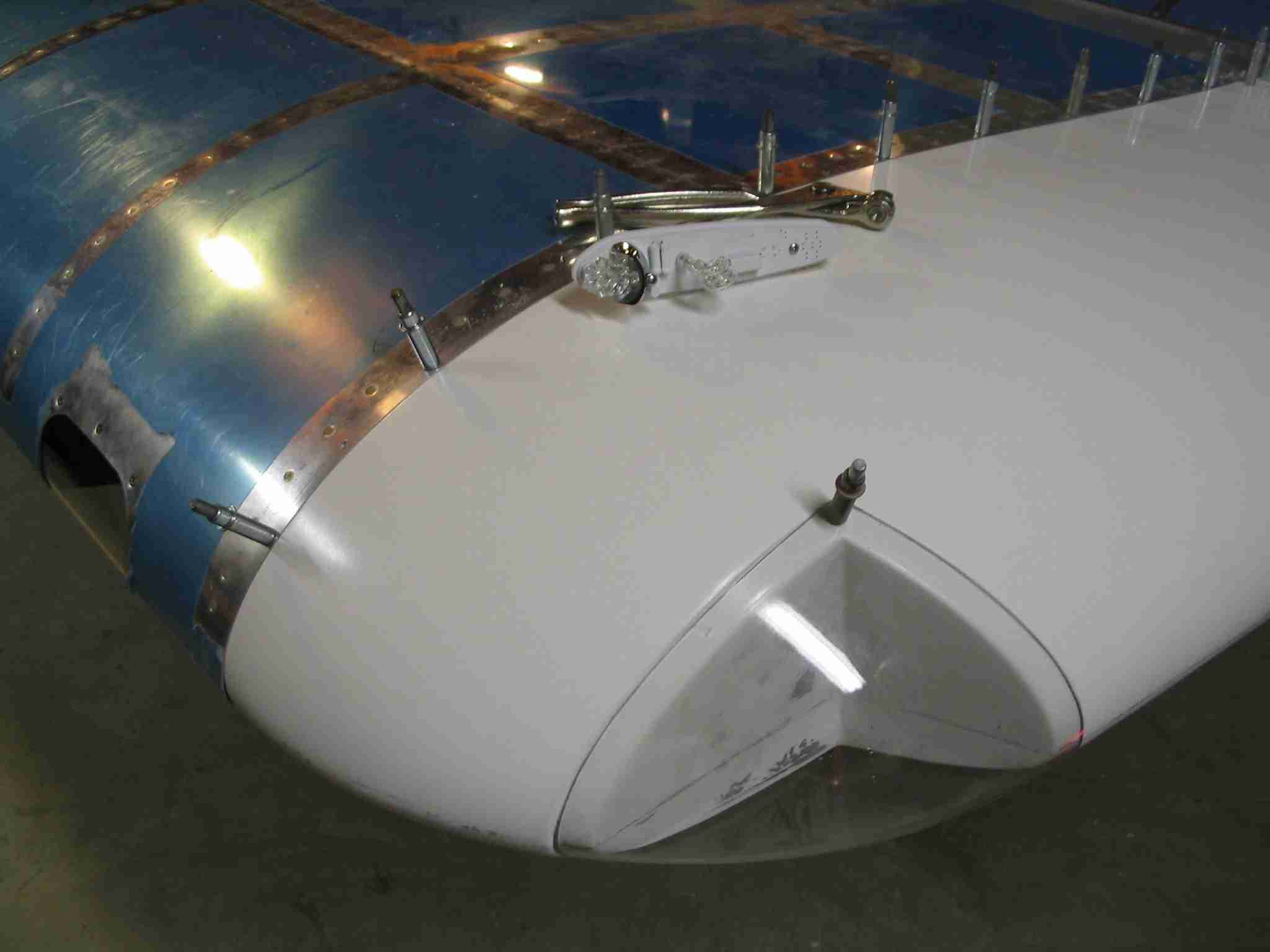
 F
Installing the the position /
strobe lights on the wing tip was fairly straight forward.
First up was taking a look at the lights. I went with
Airplane
Gear's Skybright Strobes & Lights and was surprised at how
bright the lights are. Of course, I still need to add
the wiring and try out the strobes but if they are half as
bright as the position lights my little RV-9 will be light up
like a 747. These lights use fewer LED's than some other
product available for the homebuilt market but they make up
for that by using a reflector to improve the light dispersion. (11/26/05) F
Installing the the position /
strobe lights on the wing tip was fairly straight forward.
First up was taking a look at the lights. I went with
Airplane
Gear's Skybright Strobes & Lights and was surprised at how
bright the lights are. Of course, I still need to add
the wiring and try out the strobes but if they are half as
bright as the position lights my little RV-9 will be light up
like a 747. These lights use fewer LED's than some other
product available for the homebuilt market but they make up
for that by using a reflector to improve the light dispersion. (11/26/05) |
| |
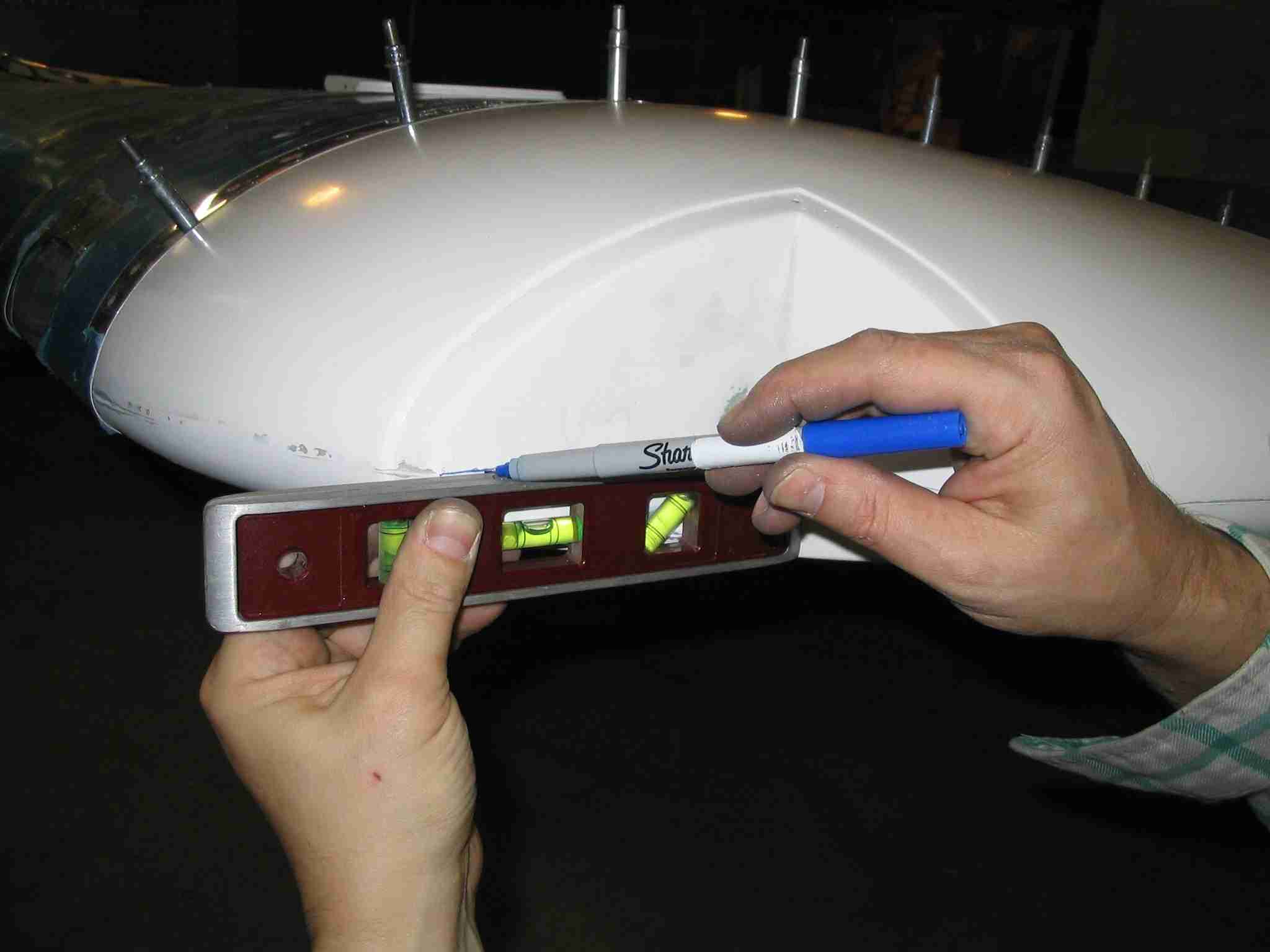
  E
The first thing I did was to make sure the wing was level.
Then I drew a "level" line in the cut out for the light.
The parting line on the fiberglass tips from Van's are close
to level but not exact. (11/26/05) E
The first thing I did was to make sure the wing was level.
Then I drew a "level" line in the cut out for the light.
The parting line on the fiberglass tips from Van's are close
to level but not exact. (11/26/05) |
| |
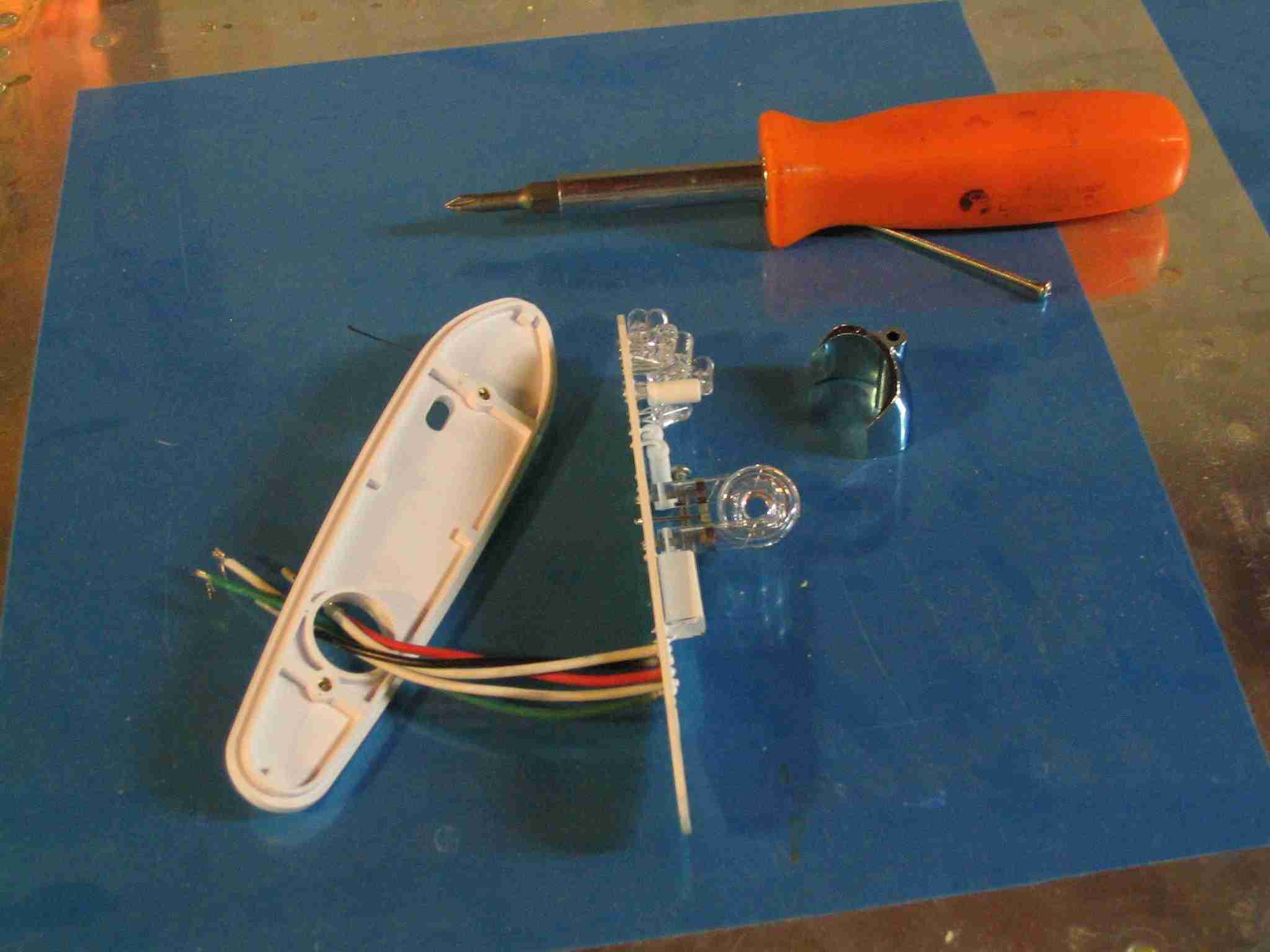
 F
Next up, disassemble the lights. Since the cutout in the
RV wingtip would shield an aft facing white light I ordered
these lights w/o the white tail light. There is a
separate white tail light / strobe that is fitted to the
rudder bottom on the new RV kits. (11/26/05) F
Next up, disassemble the lights. Since the cutout in the
RV wingtip would shield an aft facing white light I ordered
these lights w/o the white tail light. There is a
separate white tail light / strobe that is fitted to the
rudder bottom on the new RV kits. (11/26/05) |
| |
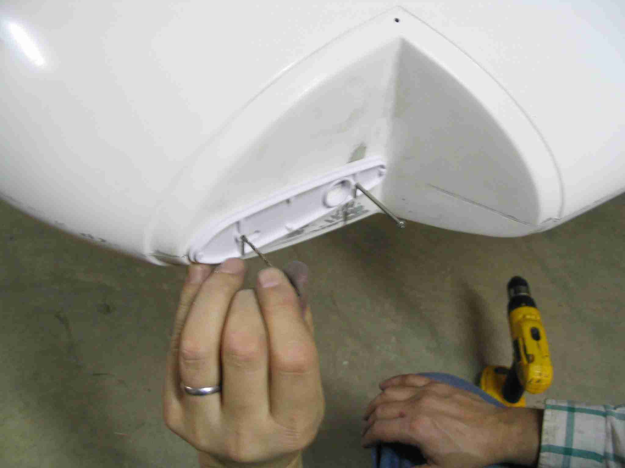
 E
The bottom plate of the light fixtures has a threaded brass
insert to hold the unit together. Using a drill bit that
just fits inside the brass fitting line up the backing plate
and turn the drill bit by hand just enough to mark the line.
Take down the plage and finish drill the hole with a power
drill. (11/26/05) E
The bottom plate of the light fixtures has a threaded brass
insert to hold the unit together. Using a drill bit that
just fits inside the brass fitting line up the backing plate
and turn the drill bit by hand just enough to mark the line.
Take down the plage and finish drill the hole with a power
drill. (11/26/05) |
| |
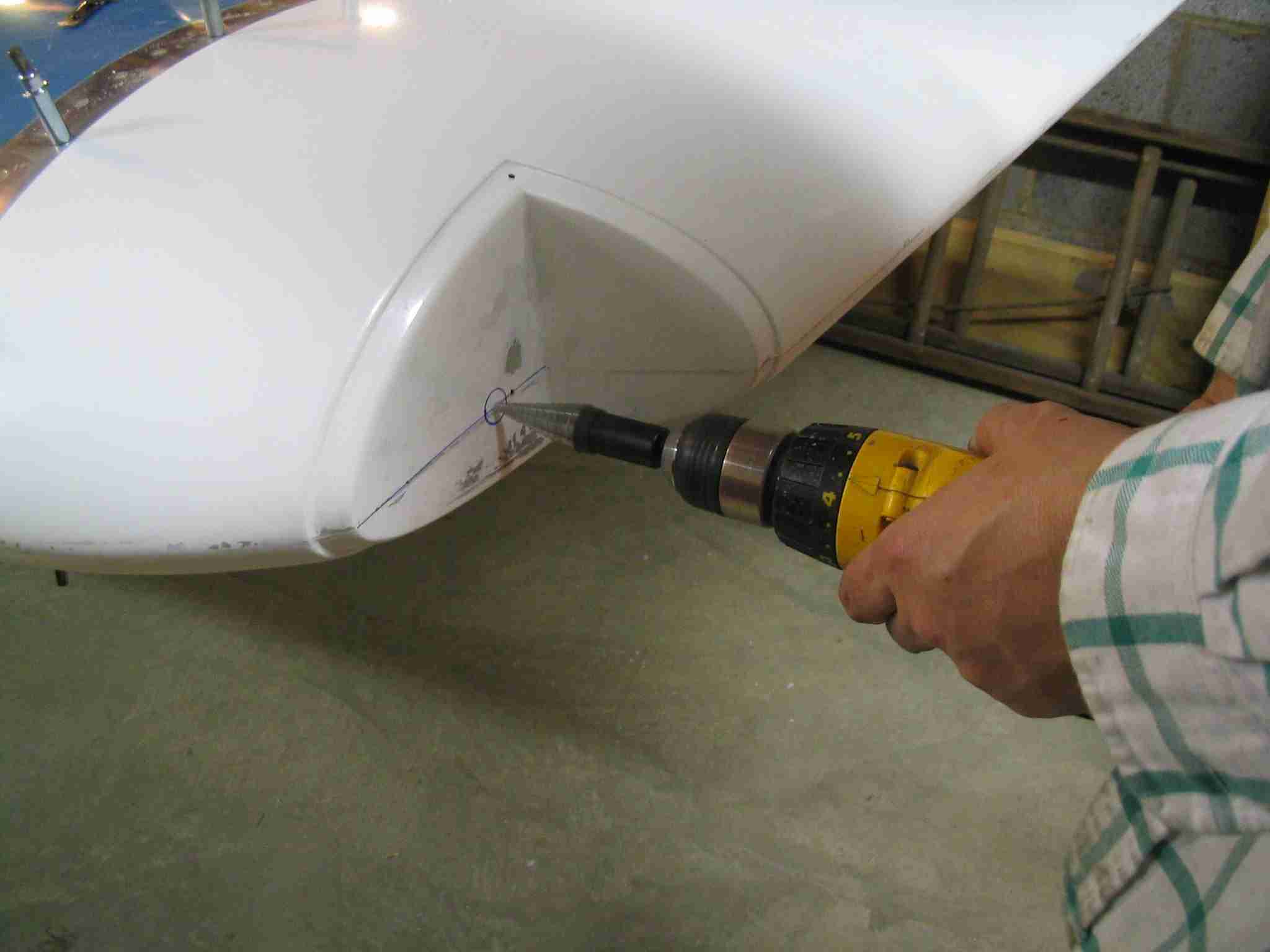
 F
With the aft screw inserted to hold the plate in place lined
it up with the level line and turn the drill bit by hand to
mark the location of the second hole. As before, remove
the backing plate and finish drill the hole. To allow
the room for the bolts, enlarge both holes with a #40 drill
bit. (11/26/05) F
With the aft screw inserted to hold the plate in place lined
it up with the level line and turn the drill bit by hand to
mark the location of the second hole. As before, remove
the backing plate and finish drill the hole. To allow
the room for the bolts, enlarge both holes with a #40 drill
bit. (11/26/05) |
| |
 E
Once both bolt holes are drilled reinstall the the plate and
mark the wire hole. Remove the plate, and drill the wire
hole to size using a uni-bit. (11/26/05) E
Once both bolt holes are drilled reinstall the the plate and
mark the wire hole. Remove the plate, and drill the wire
hole to size using a uni-bit. (11/26/05) |
| |
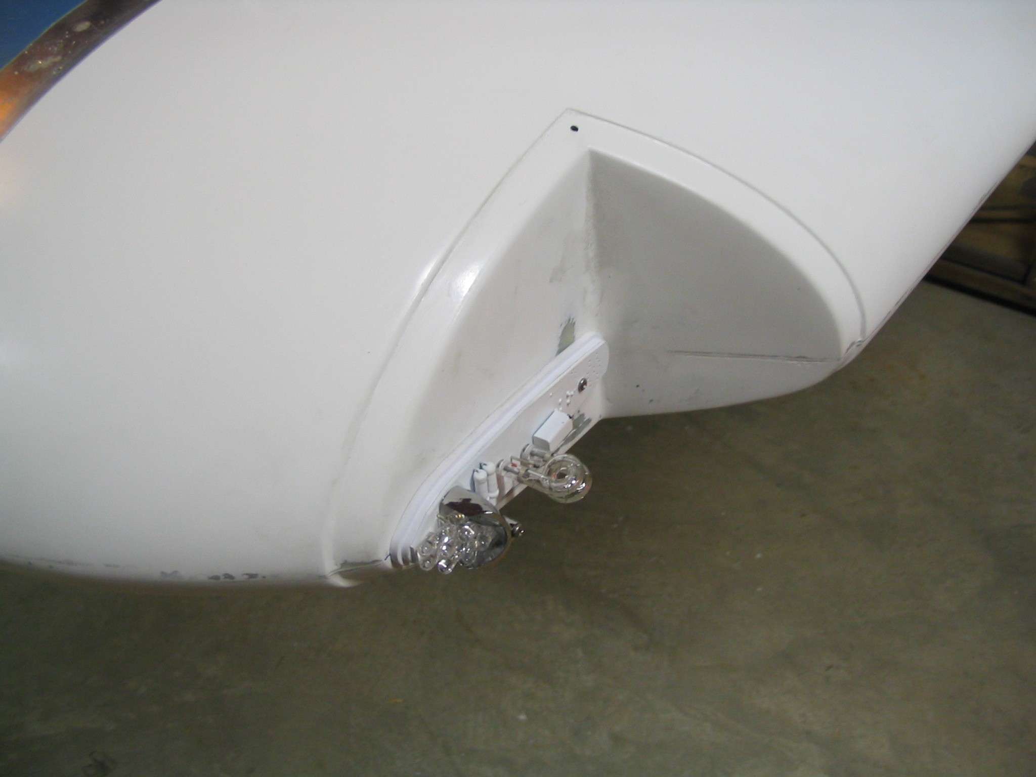
  F
After fitting and installing the first light, the results were
very pleasing. It wasn't until the lens over was fitted
that we realized the LED's and their reflector stuck out too
far and interfered with the cover. The solution was
fairly straight forward. Since this light did not
include the rear white lights, the section aft of the rear
bolt hole could be cut off w/o impact the function of the
light / strobe fixture. A few seconds on the band saw,
new holes were drilled and the light was installed. (11/26/05) F
After fitting and installing the first light, the results were
very pleasing. It wasn't until the lens over was fitted
that we realized the LED's and their reflector stuck out too
far and interfered with the cover. The solution was
fairly straight forward. Since this light did not
include the rear white lights, the section aft of the rear
bolt hole could be cut off w/o impact the function of the
light / strobe fixture. A few seconds on the band saw,
new holes were drilled and the light was installed. (11/26/05) |
| |
 E
Here is the final product. The entire installation took
less than an hour for both wings, including inspecting and
cutting the light after discovering the interference with the
initial fit. (11/26/05) E
Here is the final product. The entire installation took
less than an hour for both wings, including inspecting and
cutting the light after discovering the interference with the
initial fit. (11/26/05) |
| |
 F
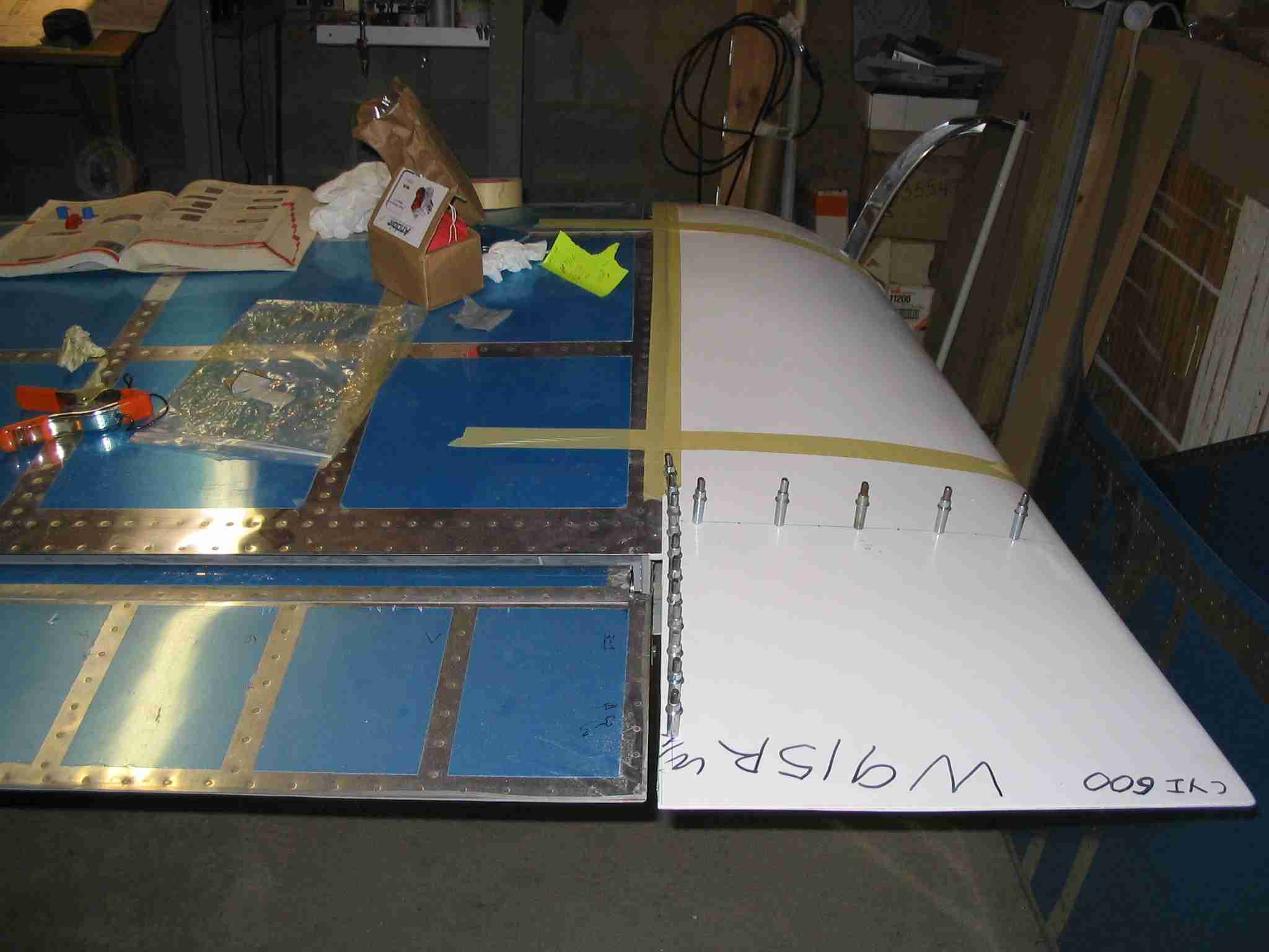
Start fitting the Wing Root Fairings (WRF) by marking them
left and right. They are identical parts right up until
you match drill them. (12/10/05) F
Start fitting the Wing Root Fairings (WRF) by marking them
left and right. They are identical parts right up until
you match drill them. (12/10/05) |
| |
 E
Remove the top and bottom inboard wing tank screws.
These screws will secure the WRF as well as the tank. (12/10/05) E
Remove the top and bottom inboard wing tank screws.
These screws will secure the WRF as well as the tank. (12/10/05) |
| |
  F
Drill, deburr, and dimple the two holes shown in this picture.
Remember to set the dimples in opposite directions on the left
and right WRF. These pictures are from the left WRF.
The inboard tank screws will go through these holes. (12/10/05) F
Drill, deburr, and dimple the two holes shown in this picture.
Remember to set the dimples in opposite directions on the left
and right WRF. These pictures are from the left WRF.
The inboard tank screws will go through these holes. (12/10/05) |
| |
  E
Cleco the WRF in place and install the two fuel tank screws.
Use a thin strip of something (wood is what I used) to set the
edge distance as the WRF wraps around the fuel tank. (12/10/05) E
Cleco the WRF in place and install the two fuel tank screws.
Use a thin strip of something (wood is what I used) to set the
edge distance as the WRF wraps around the fuel tank. (12/10/05) |
| |
 F
Prior to match drilling the holes in the fuel tank skins, mark
them with Sharpie, remove the WRF and check for edge distance.
The kit was so good that I did not have an edge distance
problem so I reinstalled the WRF and match drilled it with a
#40 drill bit. Once all the holes are match drilled I
removed the WRF, enlarged, deburred, and dimpled the holes in
them. When the wings are moved in a few weeks I will
enlarged the those holes and install plate nuts. It took
me awhile to figure this out but the holes on the top of the
wing where the wing walk doublers are get counter sunk and
thus use K1000 plate nuts. All the other holes are
dimpled and use K1100 plate nuts. (12/10/05) F
Prior to match drilling the holes in the fuel tank skins, mark
them with Sharpie, remove the WRF and check for edge distance.
The kit was so good that I did not have an edge distance
problem so I reinstalled the WRF and match drilled it with a
#40 drill bit. Once all the holes are match drilled I
removed the WRF, enlarged, deburred, and dimpled the holes in
them. When the wings are moved in a few weeks I will
enlarged the those holes and install plate nuts. It took
me awhile to figure this out but the holes on the top of the
wing where the wing walk doublers are get counter sunk and
thus use K1000 plate nuts. All the other holes are
dimpled and use K1100 plate nuts. (12/10/05) |
| |
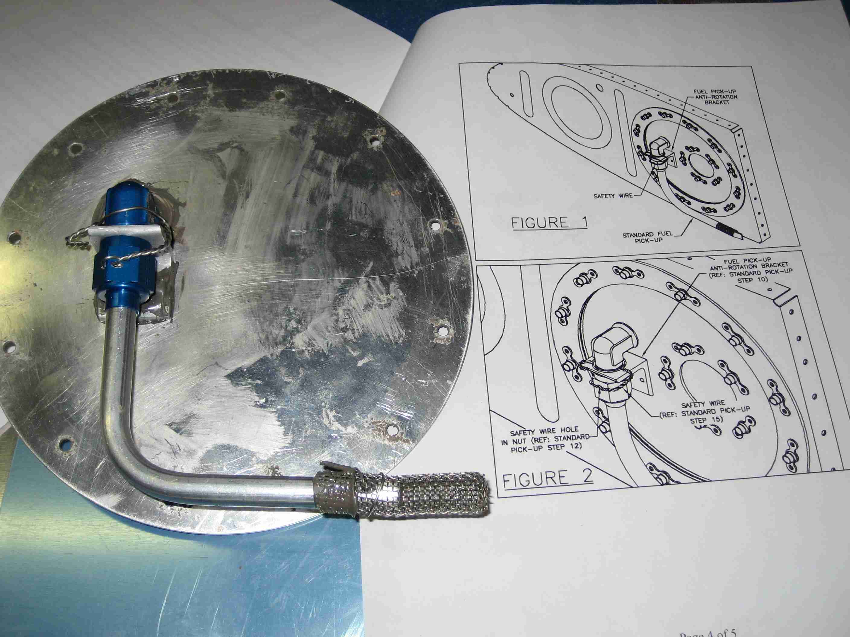
 E
Not much has happened to the wings since they were removed
from the fuselage. Last week the left wing was put on
sawhorses so I could install the plate nuts that hold the wing
root fairing in place. While I was at it I took care of
the service bulletin that requires removing the tank
inspection plate so the nut holding the fuel pickup tube could
be drilled and safety wired. Note the fuel pickup, it is
an options from Van's that not many builders seem to know
about. (03/08/07) E
Not much has happened to the wings since they were removed
from the fuselage. Last week the left wing was put on
sawhorses so I could install the plate nuts that hold the wing
root fairing in place. While I was at it I took care of
the service bulletin that requires removing the tank
inspection plate so the nut holding the fuel pickup tube could
be drilled and safety wired. Note the fuel pickup, it is
an options from Van's that not many builders seem to know
about. (03/08/07) |
| |
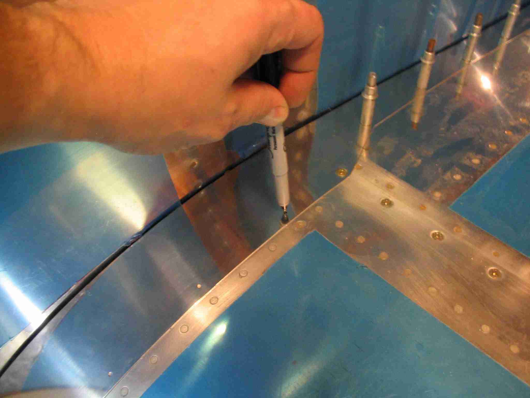
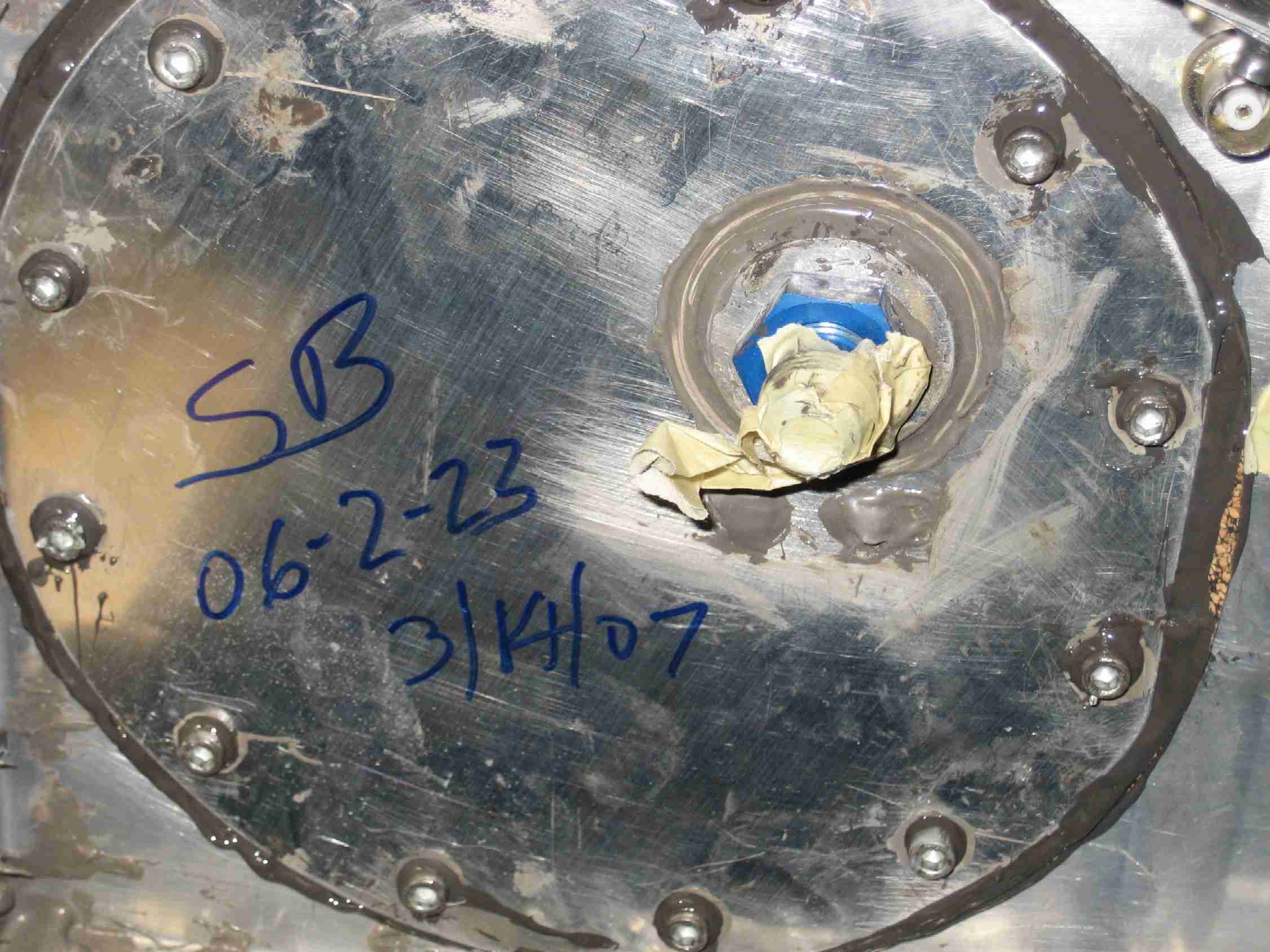
 F
The fuel pickup tube service bulletin is complete.
Another local builder wrote the SB number and date of
compliance on the tank cover, which I thought was a great idea. (03/14/07) F
The fuel pickup tube service bulletin is complete.
Another local builder wrote the SB number and date of
compliance on the tank cover, which I thought was a great idea. (03/14/07) |
| |
 E
With the fuel tank service bulletin complied with, I elected
to fill both tanks with 100LL and calibrate the Dynon D10 EMS.
I do not recommend you play with fuel in an enclosed basement
as there could be ignition sources there. In my case,
there are none, the furnace, hot water heater, etc. are all in
the garage. In addition, I had all the windows and doors
open along with fans to pull the fumes out. Still it
stunk the place up. On the good side, neither tank
leaked and the calibration was easy enough to do. (04/5/07) E
With the fuel tank service bulletin complied with, I elected
to fill both tanks with 100LL and calibrate the Dynon D10 EMS.
I do not recommend you play with fuel in an enclosed basement
as there could be ignition sources there. In my case,
there are none, the furnace, hot water heater, etc. are all in
the garage. In addition, I had all the windows and doors
open along with fans to pull the fumes out. Still it
stunk the place up. On the good side, neither tank
leaked and the calibration was easy enough to do. (04/5/07) |
| |
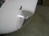
 F
After installing the wing tips I noticed they did not line up
with where the ailerons should be. The solution is to
cut the trailing edge of the wing tip and down the side.
Push it into the correct position and fiberglass it up.
Not a big deal but just another time consuming task. (5/27/07) F
After installing the wing tips I noticed they did not line up
with where the ailerons should be. The solution is to
cut the trailing edge of the wing tip and down the side.
Push it into the correct position and fiberglass it up.
Not a big deal but just another time consuming task. (5/27/07) |
| |

 E
Here I am driving the rivets Nora is bucking. (2/26/04)
E
Here I am driving the rivets Nora is bucking. (2/26/04) F
The weekend of March 21st, 22nd, & 23rd, 2004 Doug Sytsma, my
collage roommate, A&P, and Northwest Airlines Maintenance
Manager came down from Detroit to lend a hand pounding rivets.
In two days we finished riveting the left wing and started on
the right wing. (03/20/04)
F
The weekend of March 21st, 22nd, & 23rd, 2004 Doug Sytsma, my
collage roommate, A&P, and Northwest Airlines Maintenance
Manager came down from Detroit to lend a hand pounding rivets.
In two days we finished riveting the left wing and started on
the right wing. (03/20/04) E
Here it the left wing off the jig for the first time.
()3/20/04)
E
Here it the left wing off the jig for the first time.
()3/20/04)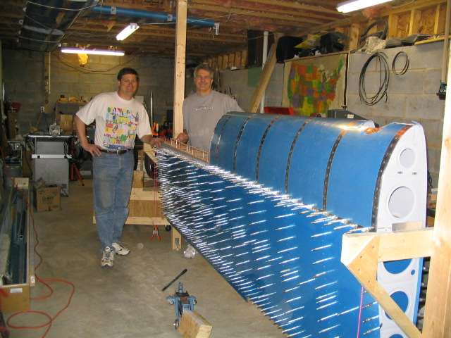 F
We even managed to assemble and match drill the right wing
during Doug's visit. Now all that is left is deburring,
dimpling, priming, and riveting. (03/21/04)
F
We even managed to assemble and match drill the right wing
during Doug's visit. Now all that is left is deburring,
dimpling, priming, and riveting. (03/21/04) E
After a long delay, Nora's Father came by on 07/31/04 to help
buck rivets on the leading edge and top skins of the right
wing. (Sorry no pictures) On August 14th John
Wigney, Europa builder and now flier, came by on short notice
to help me finish riveting the top skins on the right wing.
(08/14/04)
E
After a long delay, Nora's Father came by on 07/31/04 to help
buck rivets on the leading edge and top skins of the right
wing. (Sorry no pictures) On August 14th John
Wigney, Europa builder and now flier, came by on short notice
to help me finish riveting the top skins on the right wing.
(08/14/04)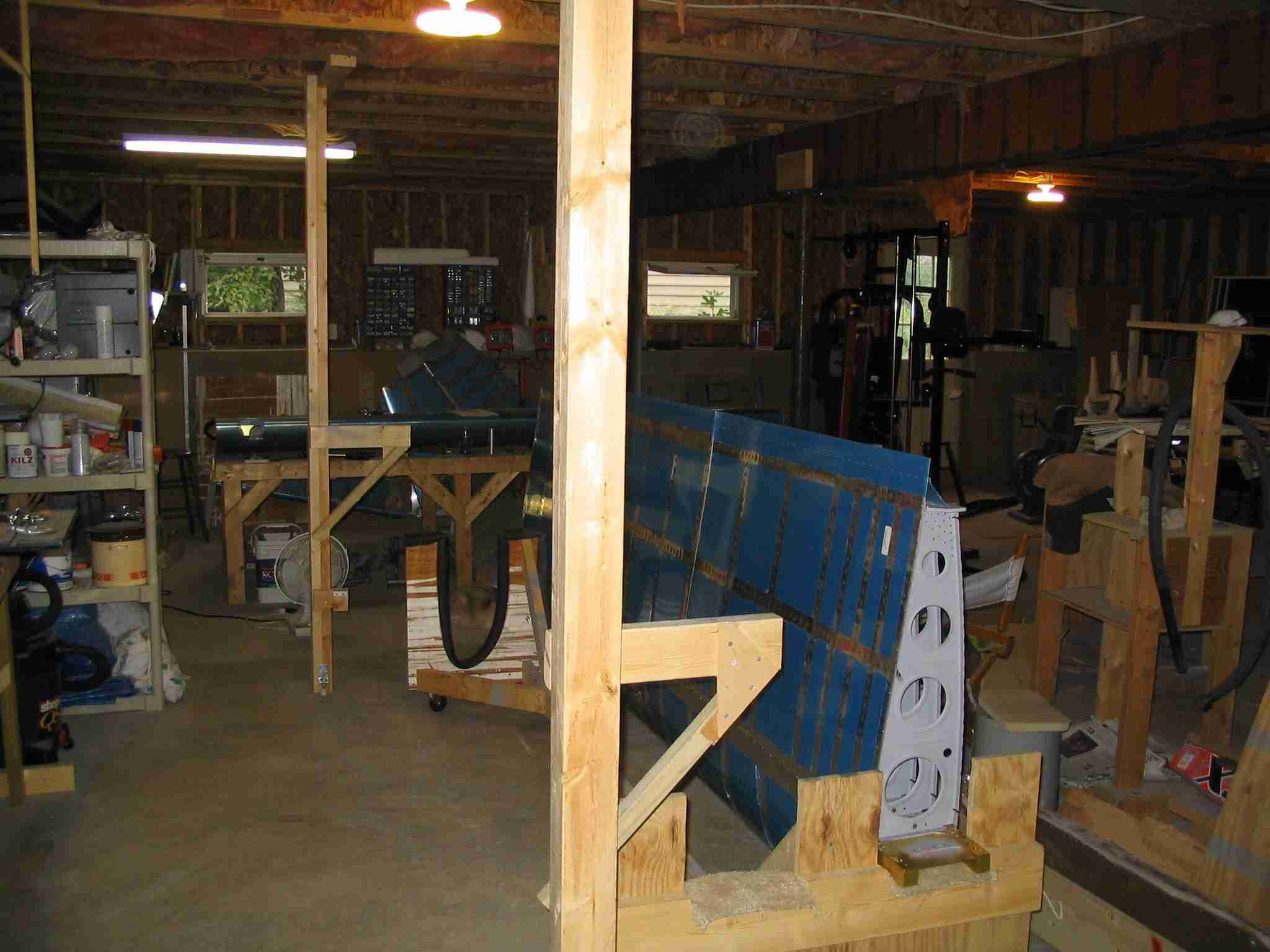 F
Four hours later John helped me lift the wing off the jig and
place it on the cradle. After John left I celebrated by
taking down the wing jig and cleaning the place up. Next
week I order the fuselage kit. (08/14/04)
F
Four hours later John helped me lift the wing off the jig and
place it on the cradle. After John left I celebrated by
taking down the wing jig and cleaning the place up. Next
week I order the fuselage kit. (08/14/04)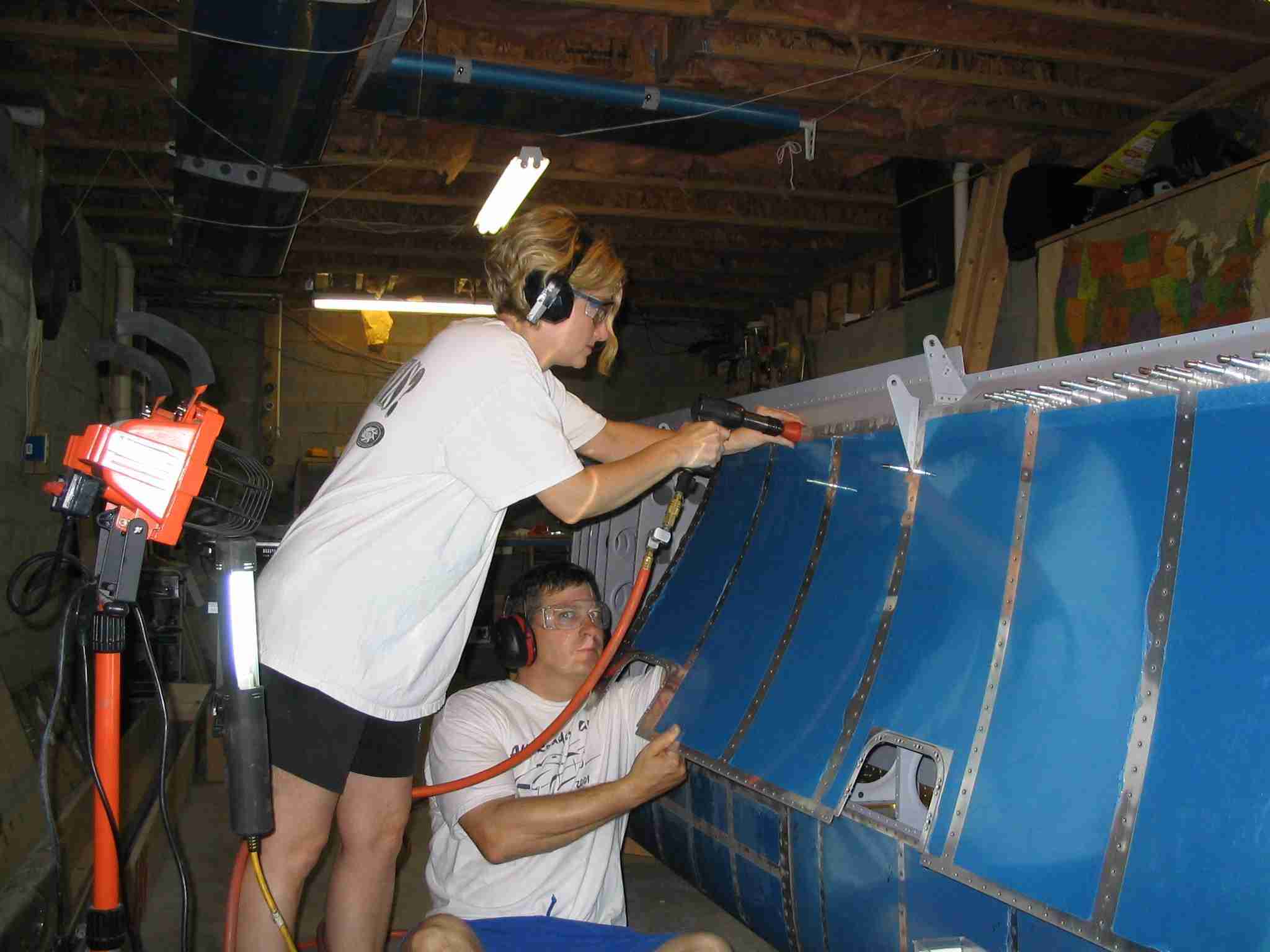 E
Six days before the wedding and here is Nora helping rivet the
bottom skin on the right wing. At least she can't say
she didn't know what she was getting herself into. (09/06/04)
E
Six days before the wedding and here is Nora helping rivet the
bottom skin on the right wing. At least she can't say
she didn't know what she was getting herself into. (09/06/04)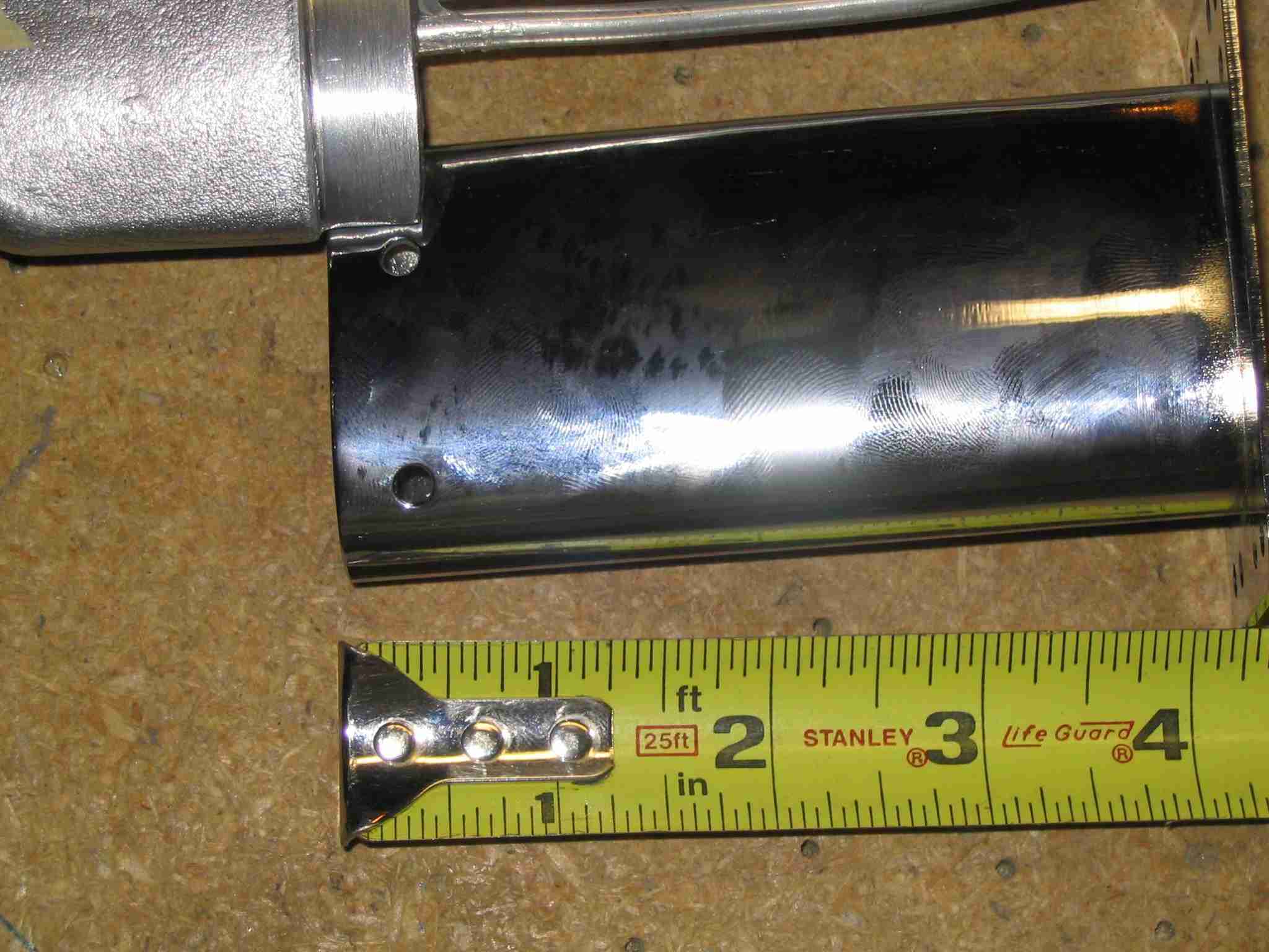 F
Last weekend
was spent cutting the left wing skin and fitting the Gretz
pitot tube mast, which is supposed to hold the Dynon pitot
tube. This pitot tube is configured to feed AOA information
to my future Dynon EFIS system. After cutting the wing skin,
drilling holes for the AOA line, etc. I test fitted the mast
and all looked good until I slid the pitot tube down the mast
and found the pre-drilled holes in the mast that are to hold
the pitot in place wouldn't leave any room for proper edge
distance on the pitot tube. I'm currently talking to both
Dynon and Warren Gretz about a solution. BTW, both the Gretz
mount and the Dynon unit seem to be top quality items and I do
expect there will be an easy resolution. (I smudged the
chrome pitot tube bracket so the flash wouldn't wash it out
.) (09/25/04)
F
Last weekend
was spent cutting the left wing skin and fitting the Gretz
pitot tube mast, which is supposed to hold the Dynon pitot
tube. This pitot tube is configured to feed AOA information
to my future Dynon EFIS system. After cutting the wing skin,
drilling holes for the AOA line, etc. I test fitted the mast
and all looked good until I slid the pitot tube down the mast
and found the pre-drilled holes in the mast that are to hold
the pitot in place wouldn't leave any room for proper edge
distance on the pitot tube. I'm currently talking to both
Dynon and Warren Gretz about a solution. BTW, both the Gretz
mount and the Dynon unit seem to be top quality items and I do
expect there will be an easy resolution. (I smudged the
chrome pitot tube bracket so the flash wouldn't wash it out
.) (09/25/04)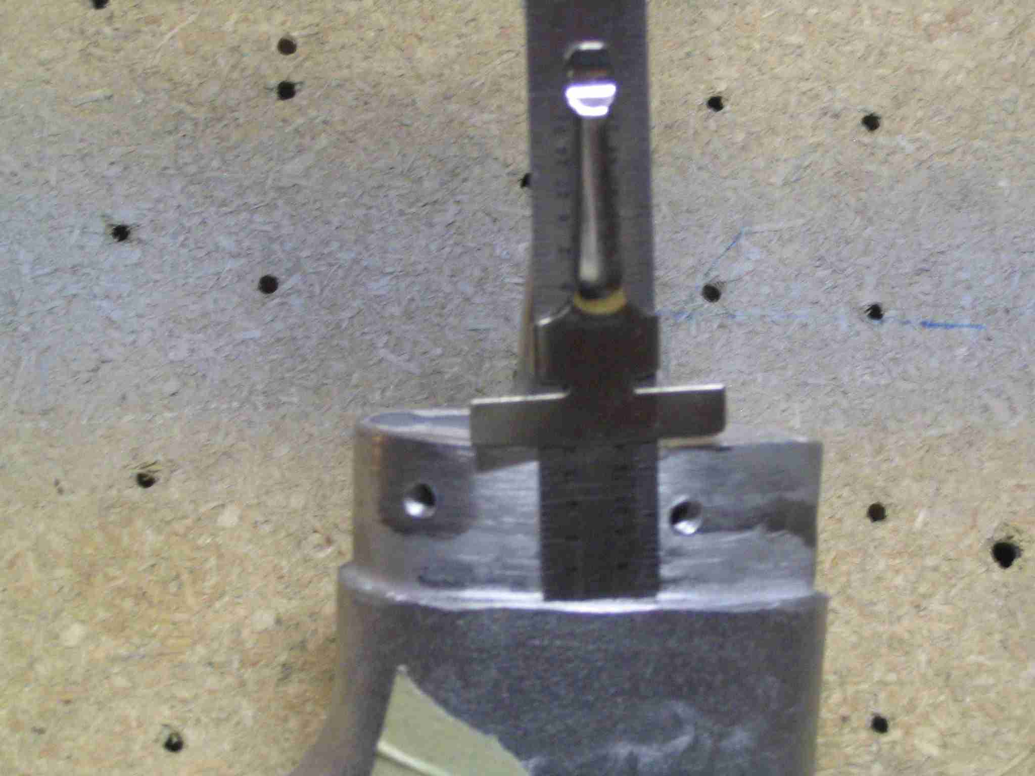 F
One other reason for the delay was the Dynon pitot tube had to
be modified by filing down the neck so it would fit into the
Gretz mount far enough that the #6 screws used to secure it
would have enough edge space. Some careful work on the
belt sander, followed by hand filing did the trick.
(10/26/04)
F
One other reason for the delay was the Dynon pitot tube had to
be modified by filing down the neck so it would fit into the
Gretz mount far enough that the #6 screws used to secure it
would have enough edge space. Some careful work on the
belt sander, followed by hand filing did the trick.
(10/26/04)