|
  _small.jpg) E
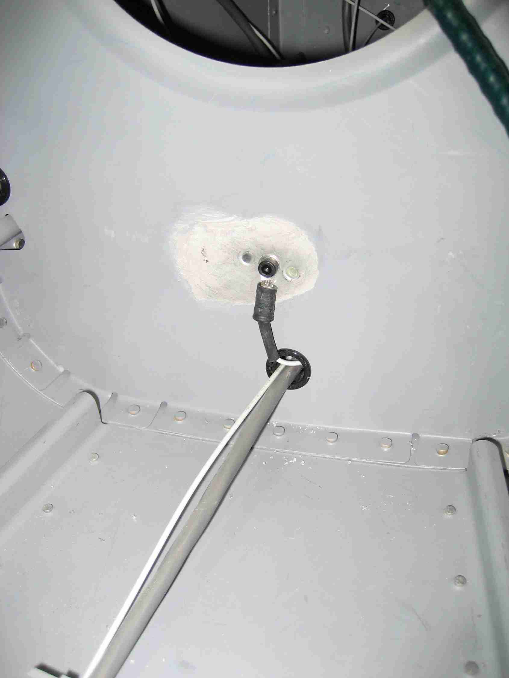
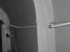
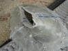
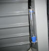
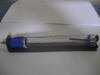
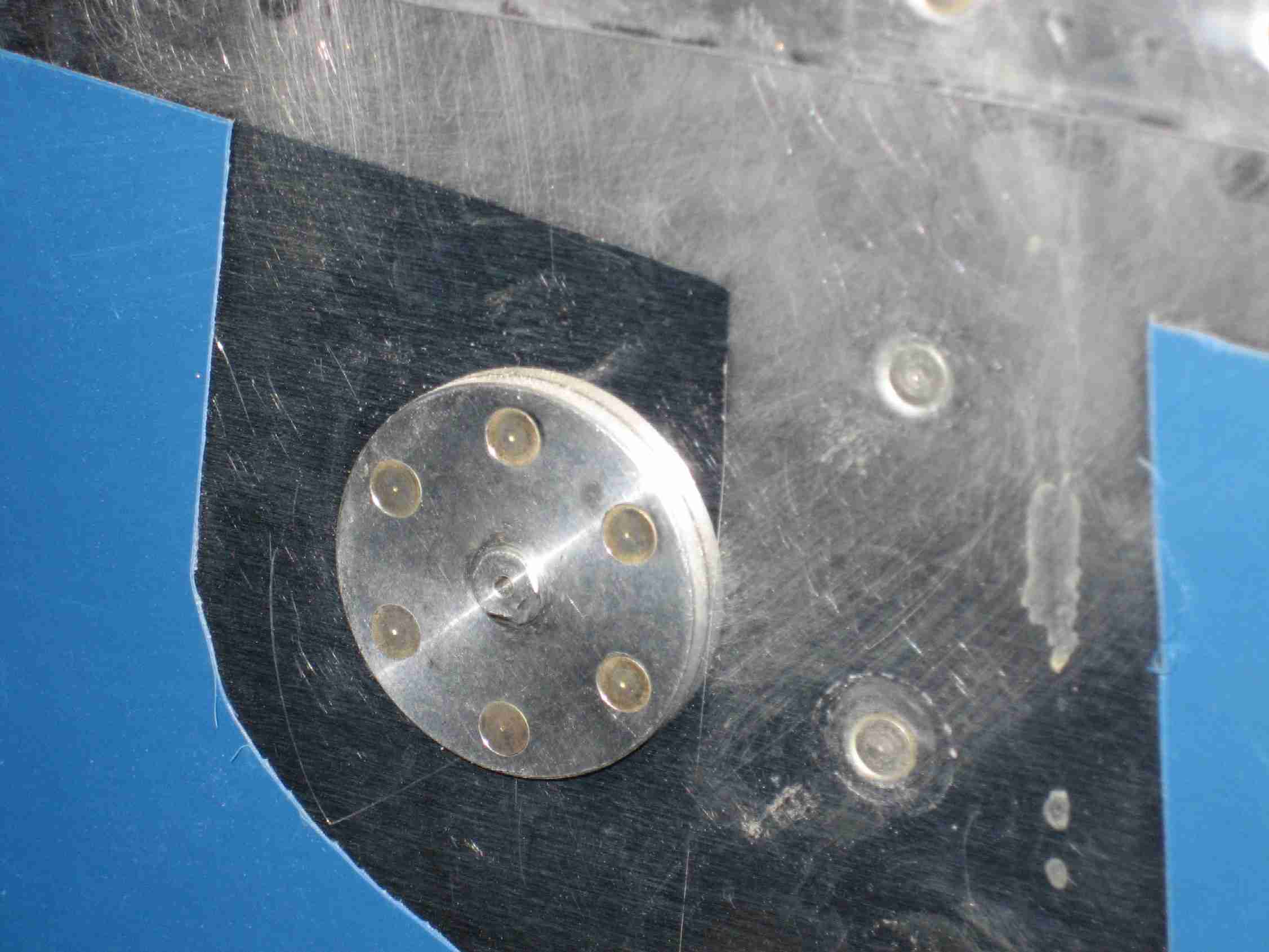
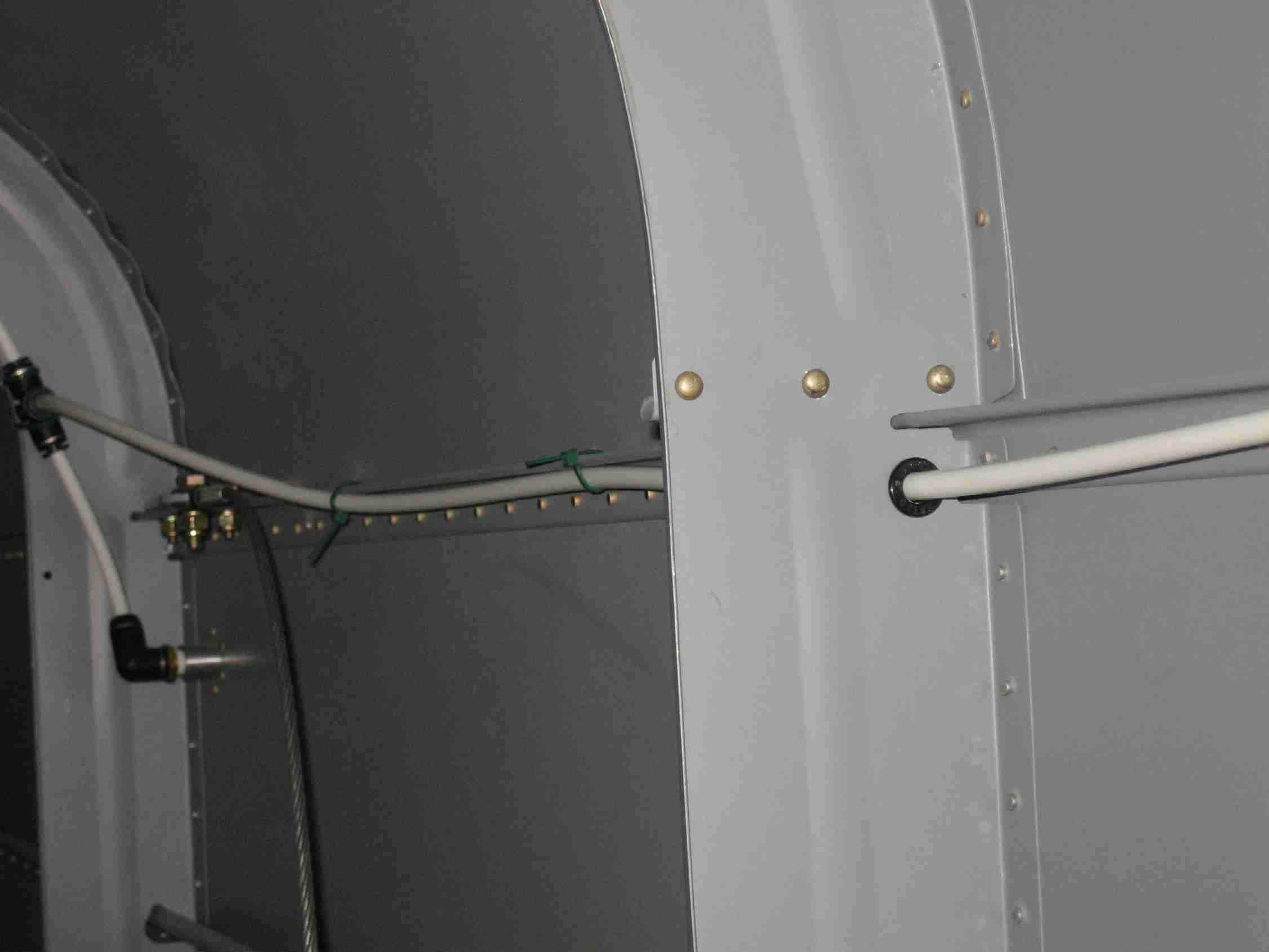
Recently, I was sent an email asking me how about the static
ports I installed and how they were connected. After
reading a good bit on the Van's Air Force forum regarding
static ports I elected to purchase the flush mount static
ports from SafeAir1 and surface mount them. Note the
nipple in the first picture, it is designed to be flush with
the skin. The second and third pictures shows the static
lines running up around one bulkhead and through the second.
In this installation, #30 holes were drilled in the longerons
and then zip-tied in place. Notice how the static line
running to the instruments is well above the static port.
This prevents (I hope!) water from entering the static system.
(2/9/07) E
Recently, I was sent an email asking me how about the static
ports I installed and how they were connected. After
reading a good bit on the Van's Air Force forum regarding
static ports I elected to purchase the flush mount static
ports from SafeAir1 and surface mount them. Note the
nipple in the first picture, it is designed to be flush with
the skin. The second and third pictures shows the static
lines running up around one bulkhead and through the second.
In this installation, #30 holes were drilled in the longerons
and then zip-tied in place. Notice how the static line
running to the instruments is well above the static port.
This prevents (I hope!) water from entering the static system.
(2/9/07) |
| |
|
 F
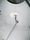
Working down the list of little things to complete before
moving to the airport including finding a ground for the tail
position light. Although all the electrical equipment is
grounded on the firewall with the exception of the stores and
the wing position lights, I thought the tail light could be
grounded locally as well. Only one problem, my fuselage
is complete. What you see in this picture is the forward
side of the F720 bulkhead. I used some acetone to remove
the SEM primer to expose the aluminum so there will be a good
ground. The 16 AWG wire goes aft through the next two
bulkheads and into the rudder bottom. (3/8/07) F
Working down the list of little things to complete before
moving to the airport including finding a ground for the tail
position light. Although all the electrical equipment is
grounded on the firewall with the exception of the stores and
the wing position lights, I thought the tail light could be
grounded locally as well. Only one problem, my fuselage
is complete. What you see in this picture is the forward
side of the F720 bulkhead. I used some acetone to remove
the SEM primer to expose the aluminum so there will be a good
ground. The 16 AWG wire goes aft through the next two
bulkheads and into the rudder bottom. (3/8/07) |
| |
|
  E
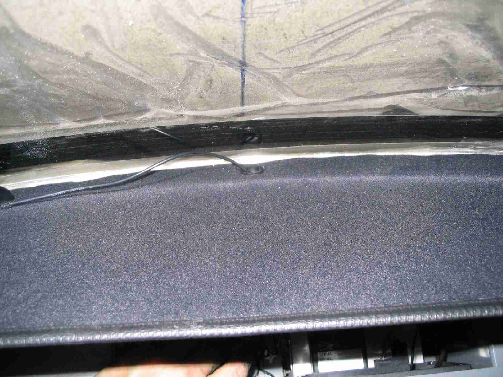
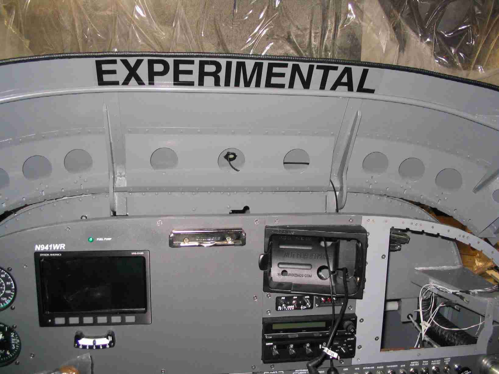
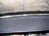
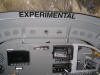
Working just an hour I feel like I accomplished a lot today.
The first picture on the left is the top of the glair shield.
Loop Velcro cloth was glued to the top of the glair shield, a
grommet was installed to protect the GPS and XM radio antennas
that have to pas through it and edge banding was installed to
trim it out nicely. To cap it off, I installed the
"EXPERIMENTAL" sticker on the bottom side of the glair shield.
No missing that when getting in and with the canopy closed,
you won't see it. (3/15/07) E
Working just an hour I feel like I accomplished a lot today.
The first picture on the left is the top of the glair shield.
Loop Velcro cloth was glued to the top of the glair shield, a
grommet was installed to protect the GPS and XM radio antennas
that have to pas through it and edge banding was installed to
trim it out nicely. To cap it off, I installed the
"EXPERIMENTAL" sticker on the bottom side of the glair shield.
No missing that when getting in and with the canopy closed,
you won't see it. (3/15/07) |
| |
| |
|
 F
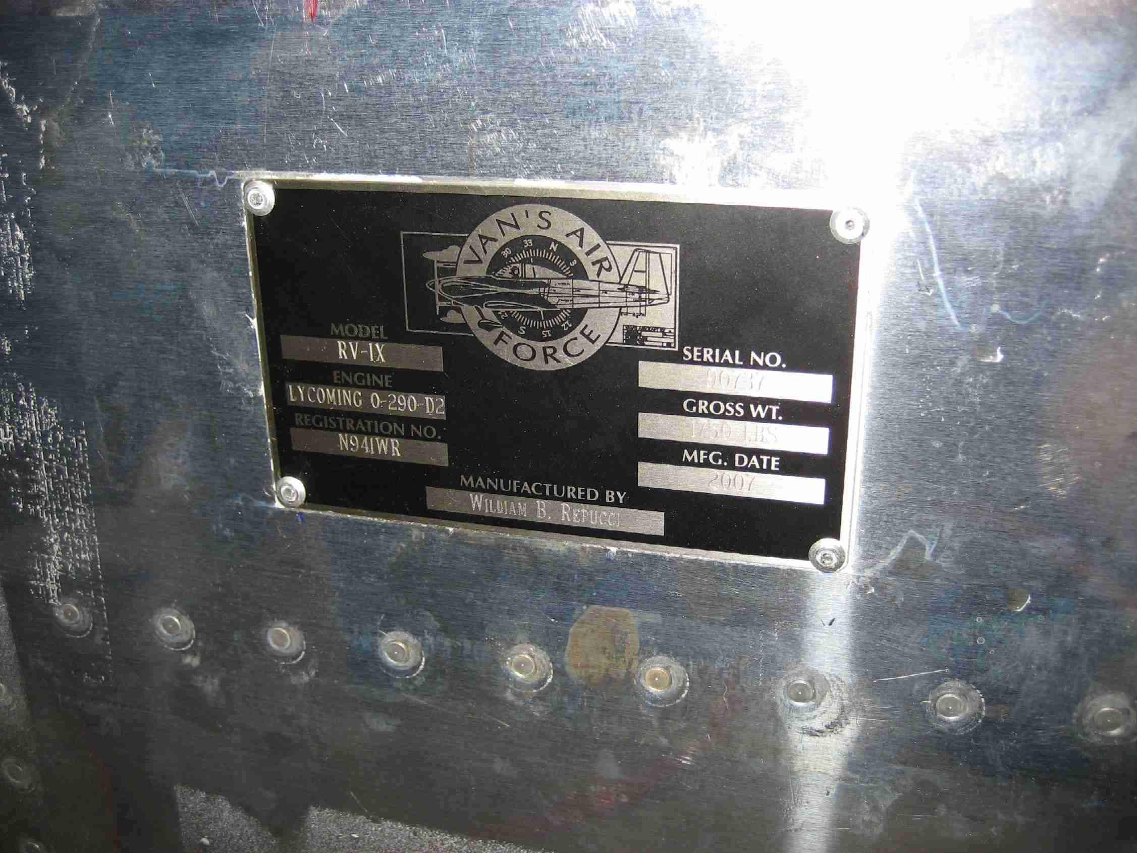
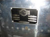
Some times you just have to work with your spouse on some
things. The other night I took Nora out for dinner at
the mall that just happens to have a "Things Remembered" store
in it. So I brought along the Van's data plate and had
it engraved for $41. It took a day but when I got home I
drilled it to the aft left fuselage, under the HS.
Before pop-riveting it in place I etched, alodined, and
painted underneath it. (5/17/07) F
Some times you just have to work with your spouse on some
things. The other night I took Nora out for dinner at
the mall that just happens to have a "Things Remembered" store
in it. So I brought along the Van's data plate and had
it engraved for $41. It took a day but when I got home I
drilled it to the aft left fuselage, under the HS.
Before pop-riveting it in place I etched, alodined, and
painted underneath it. (5/17/07) |
| |
|
 E
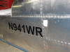
The top forward skin has now been riveted in place and I'm yet
to take a picture of it, maybe tomorrow. Tonight I
cleaned up the adhesive left over from doing fiberglass work
on the tail section and applied the temporary N-number.
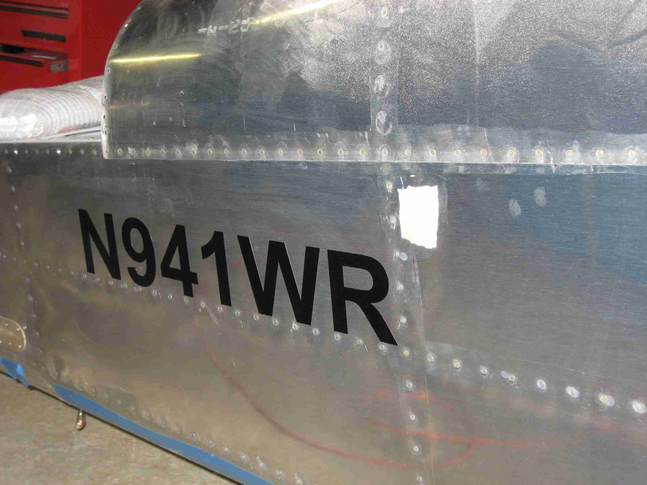
The "list" is getting shorter every day. (5/27/07) E
The top forward skin has now been riveted in place and I'm yet
to take a picture of it, maybe tomorrow. Tonight I
cleaned up the adhesive left over from doing fiberglass work
on the tail section and applied the temporary N-number.
The "list" is getting shorter every day. (5/27/07) |
| |
|
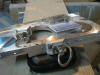
 F
Doug Bell makes these drop in replacement tail wheels for
around $200, money well spent, IMHO. The real advantage
to this type of tail wheel is that it presents the face of the
wheel to any pothole the tail might drop into. This will
allow the wheel to climb up out of the hole. Van's
standard tail wheel works more like a tail hook and has been
known to catch on things, like if you dropped the tail off the
edge of a concrete pad, and pull the aft two bulkheads out.
The other thing to notice is the Eye-bolts used to attach the
steering spring. A similar arrangement is put on the
bottom of the rudder horn. The advantage here is the
spring is almost horizontal and should be out of the way of
the rudder bottom. In addition, when the spring starts
wearing away at the attachment points, the Eye-bolts are easy to
replace. This
was not my idea, it was in one of the OLD RVaitors, which are
good reading.
(Parts List, four of each are required:
Eye
Bold Drilled AN42B-5, Cable Shackles AN115-21, Bolt AN3-6
(Drilled shank), Washer AN960-10, Castle nut AN310-3, Cotter
pins as needed) F
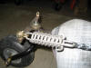
Doug Bell makes these drop in replacement tail wheels for
around $200, money well spent, IMHO. The real advantage
to this type of tail wheel is that it presents the face of the
wheel to any pothole the tail might drop into. This will
allow the wheel to climb up out of the hole. Van's
standard tail wheel works more like a tail hook and has been
known to catch on things, like if you dropped the tail off the
edge of a concrete pad, and pull the aft two bulkheads out.
The other thing to notice is the Eye-bolts used to attach the
steering spring. A similar arrangement is put on the
bottom of the rudder horn. The advantage here is the
spring is almost horizontal and should be out of the way of
the rudder bottom. In addition, when the spring starts
wearing away at the attachment points, the Eye-bolts are easy to
replace. This
was not my idea, it was in one of the OLD RVaitors, which are
good reading.
(Parts List, four of each are required:
Eye
Bold Drilled AN42B-5, Cable Shackles AN115-21, Bolt AN3-6
(Drilled shank), Washer AN960-10, Castle nut AN310-3, Cotter
pins as needed)
The wheel bolt is long and bushed out on
purpose so a Cessna tow bar may be used on the tail wheel.
(The white bag is 20 lbs of OO buck shot. It is helping
hold the tail down with the engine mounted and no tail or
wings installed.) (5/27/07) |
| |
|
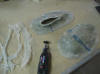
 E
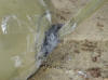
Most RV builders don't enjoy working with fiberglass.
Yes, it can be a itchy and you MUST protect yourself from it
but I find the ease at which you can make unusual shapes just
amazing. The first step it align the gear leg fairings
so the plane flies straight. (The upper intersection
fairings on my plane are RV-7 parts from Van's and were good
enough to line up the gear leg fairings. They aren't
pretty and I will clean them up in the weeks to come.)
Everything was taped off so the fiberglass would not stick to
the leg fairings or wheel pants. Modeling clay to shape the
fairing. This picture was taken midway through the
forming process. (5/17/08) E
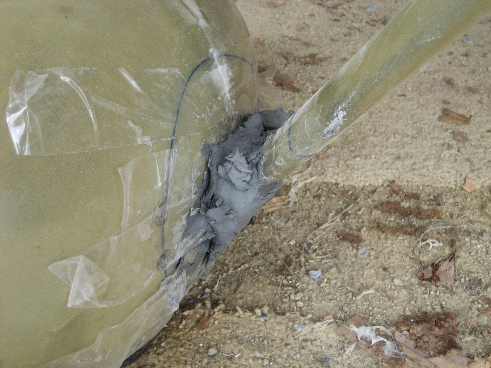
Most RV builders don't enjoy working with fiberglass.
Yes, it can be a itchy and you MUST protect yourself from it
but I find the ease at which you can make unusual shapes just
amazing. The first step it align the gear leg fairings
so the plane flies straight. (The upper intersection
fairings on my plane are RV-7 parts from Van's and were good
enough to line up the gear leg fairings. They aren't
pretty and I will clean them up in the weeks to come.)
Everything was taped off so the fiberglass would not stick to
the leg fairings or wheel pants. Modeling clay to shape the
fairing. This picture was taken midway through the
forming process. (5/17/08) |
| |
|
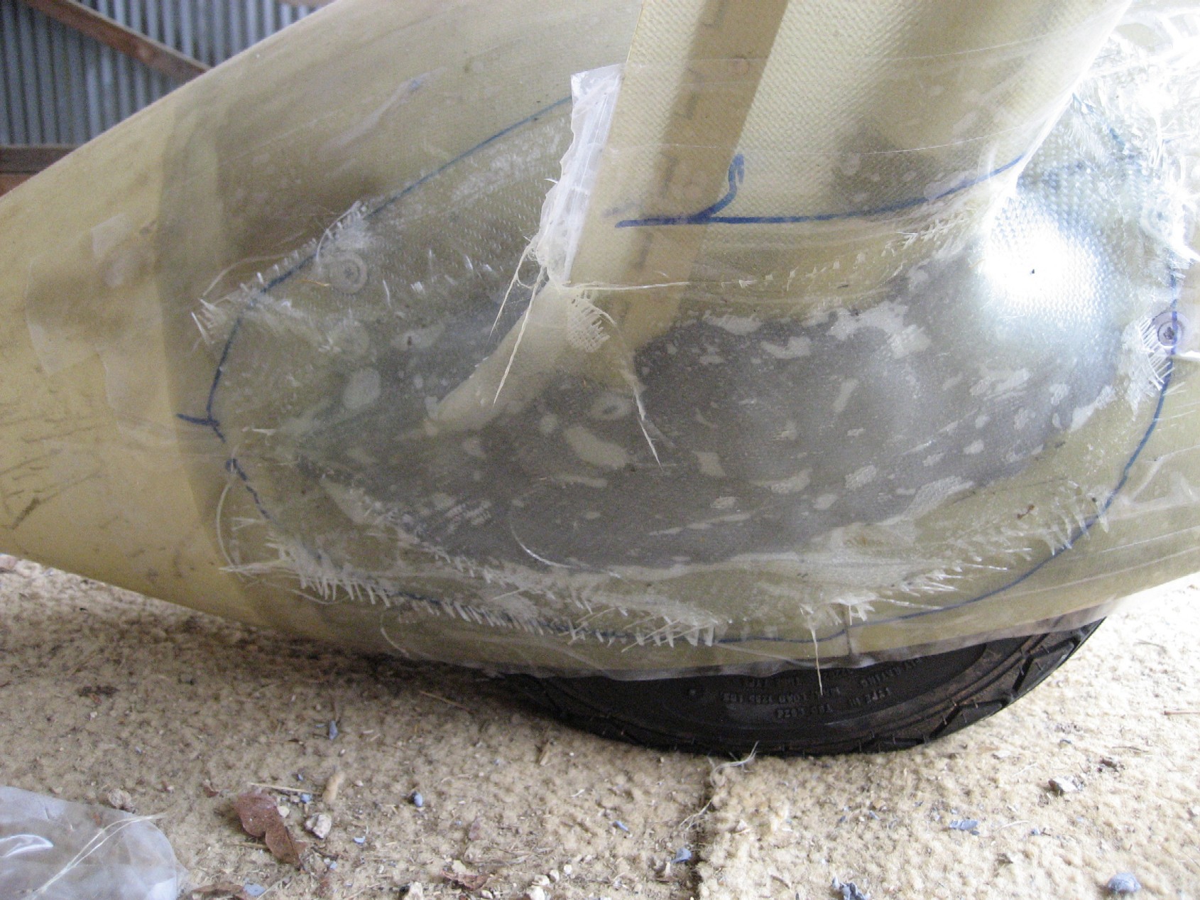
 F
Once the clay is the shape you want it, lay some fiberglass
over it. In this case I put two layers of bi-directional
cloth on it. One helpful tip, draw on the wheel pant how
far you want the fiberglass to extend past the clay.
(5/17/08) F
Once the clay is the shape you want it, lay some fiberglass
over it. In this case I put two layers of bi-directional
cloth on it. One helpful tip, draw on the wheel pant how
far you want the fiberglass to extend past the clay.
(5/17/08) |
|
|
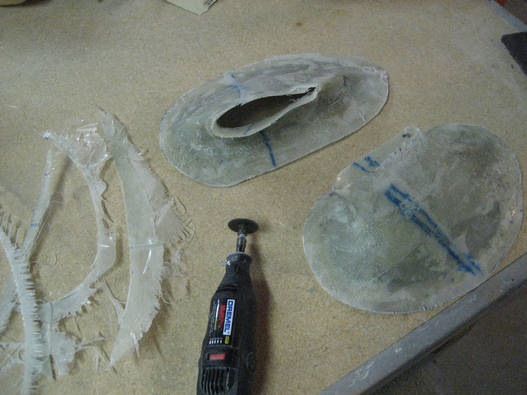
 E After the FG hardened, a
metal putty knife was slid between the new FG and the packing
tape. This popped the fairing loose without any
problems. To remove the fairing I drew a line from the
wheel pant part line to the widest part of the gear leg
fairing on both the upper and lower part of the fairing.
A Dremal was then used to cut the split line on the lower
fairing which facilitated its removal. (5/17/08)
E After the FG hardened, a
metal putty knife was slid between the new FG and the packing
tape. This popped the fairing loose without any
problems. To remove the fairing I drew a line from the
wheel pant part line to the widest part of the gear leg
fairing on both the upper and lower part of the fairing.
A Dremal was then used to cut the split line on the lower
fairing which facilitated its removal. (5/17/08) |
| |
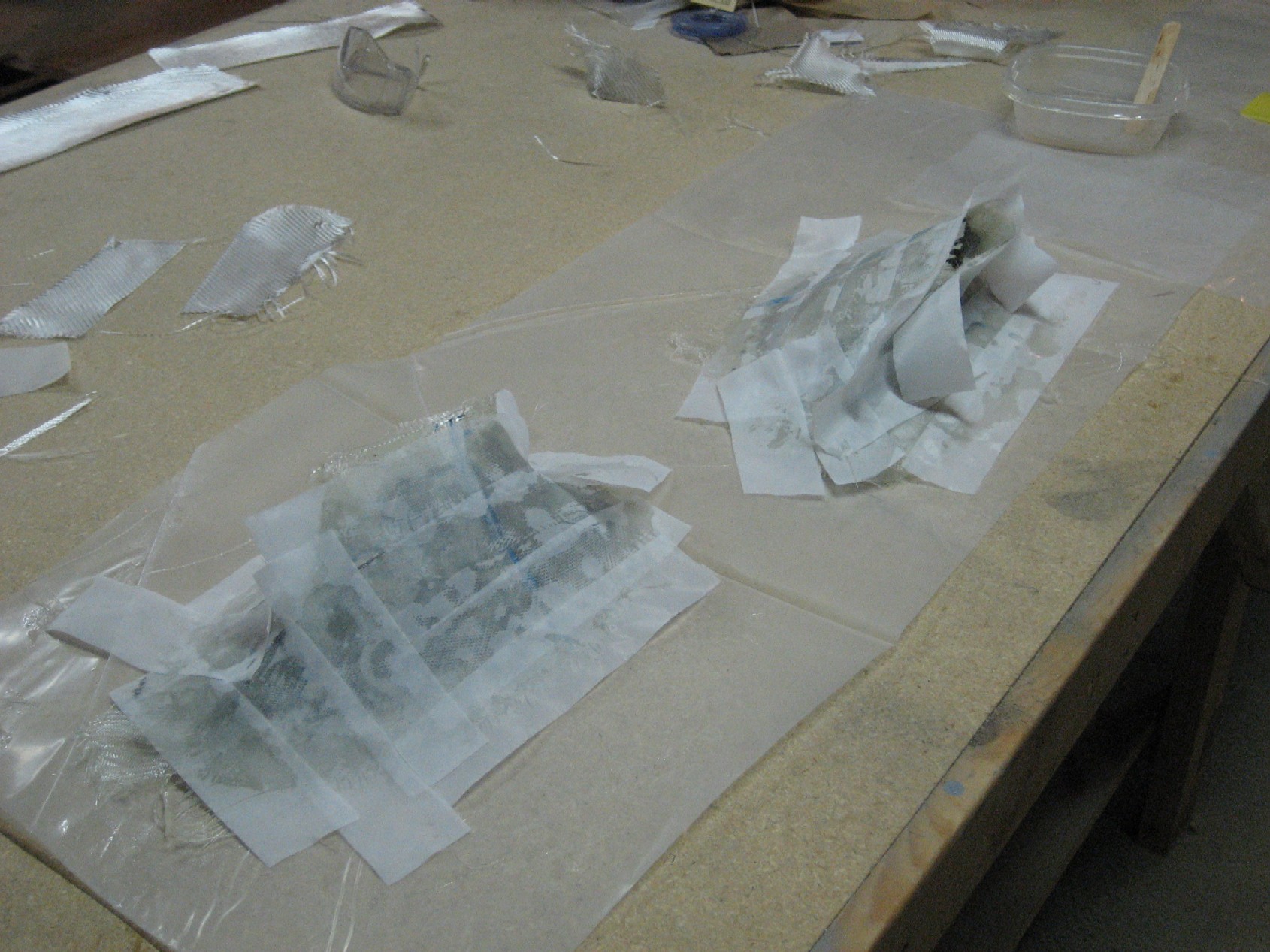
  F
With the fairing back at my shop it was easy enough to trim
and split the rest of the way. However, prior to
splitting them, a second layer of fiberglass was laid up and
this time peel-ply was used to help smooth the surface.
(5/17/08) F
With the fairing back at my shop it was easy enough to trim
and split the rest of the way. However, prior to
splitting them, a second layer of fiberglass was laid up and
this time peel-ply was used to help smooth the surface.
(5/17/08) |
| |
|
[Sorry, no picture available] E
After the fairings were trimmed the wheel pants were installed
back on the plane. With the fairings positioned properly they
were drilled to the wheel pants and held in place with cleco's.
(Dipping the cleco's in Vaseline keeps the fiberglass from
sticking to them. A mix of flox and epoxy was used to
glue them to the wheel pants. Once that hardened, I
sanded down the edge of the intersection fairing and laid on
two more layers of fiberglass over the edge and wheel pants.
These strips were no wider than an inch and a half. This
may be overkill but I figure the wheel pants take one heck of
a beating, especially on grass fields. (5/17/08) |
| |
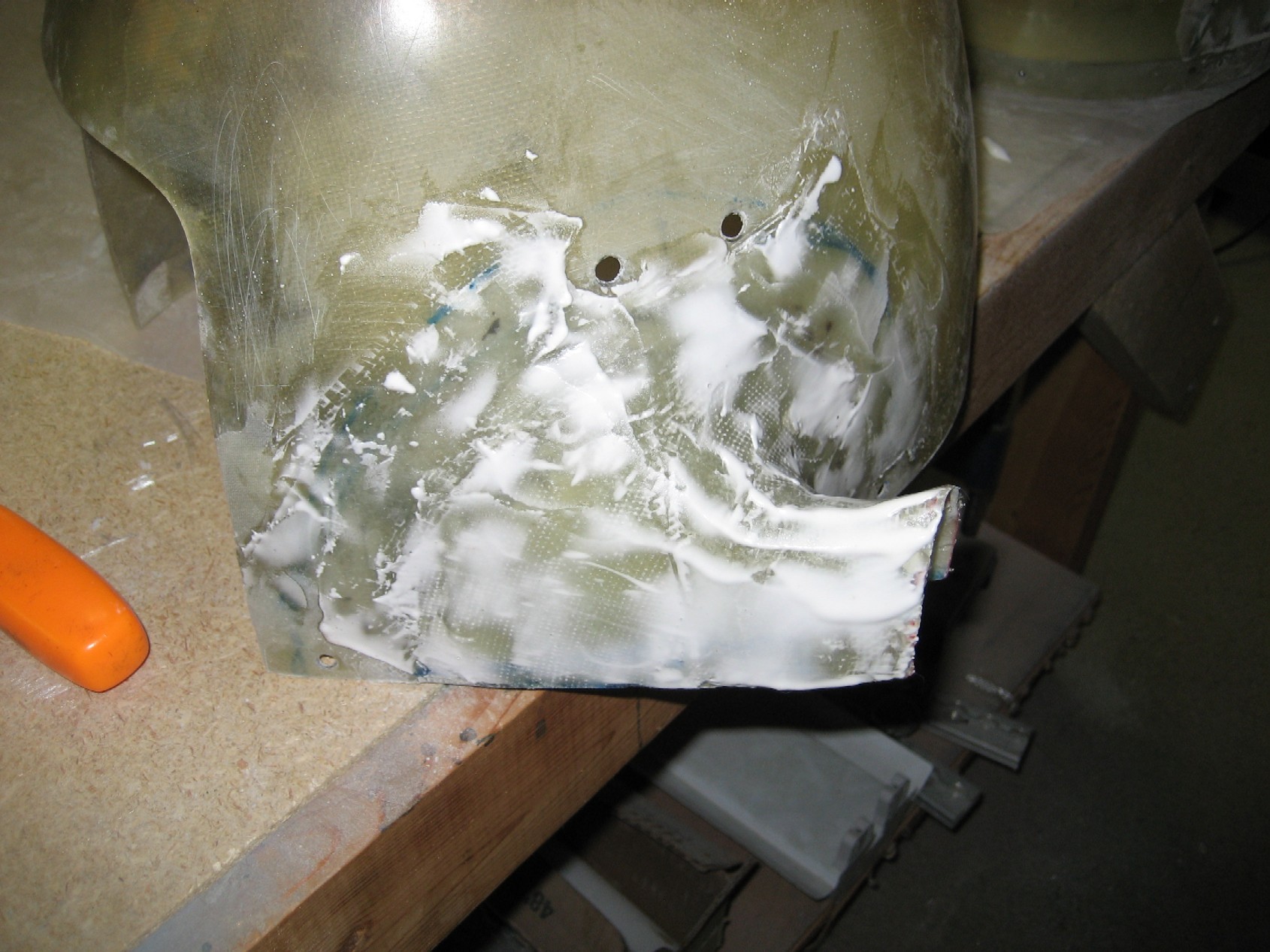
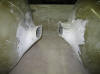
 F With all that work done, it
was time to sand the fiberglass and use micro-balloons and
epoxy to start filling the imperfections in the fairing.
(5/17/08)
F With all that work done, it
was time to sand the fiberglass and use micro-balloons and
epoxy to start filling the imperfections in the fairing.
(5/17/08) |
| |
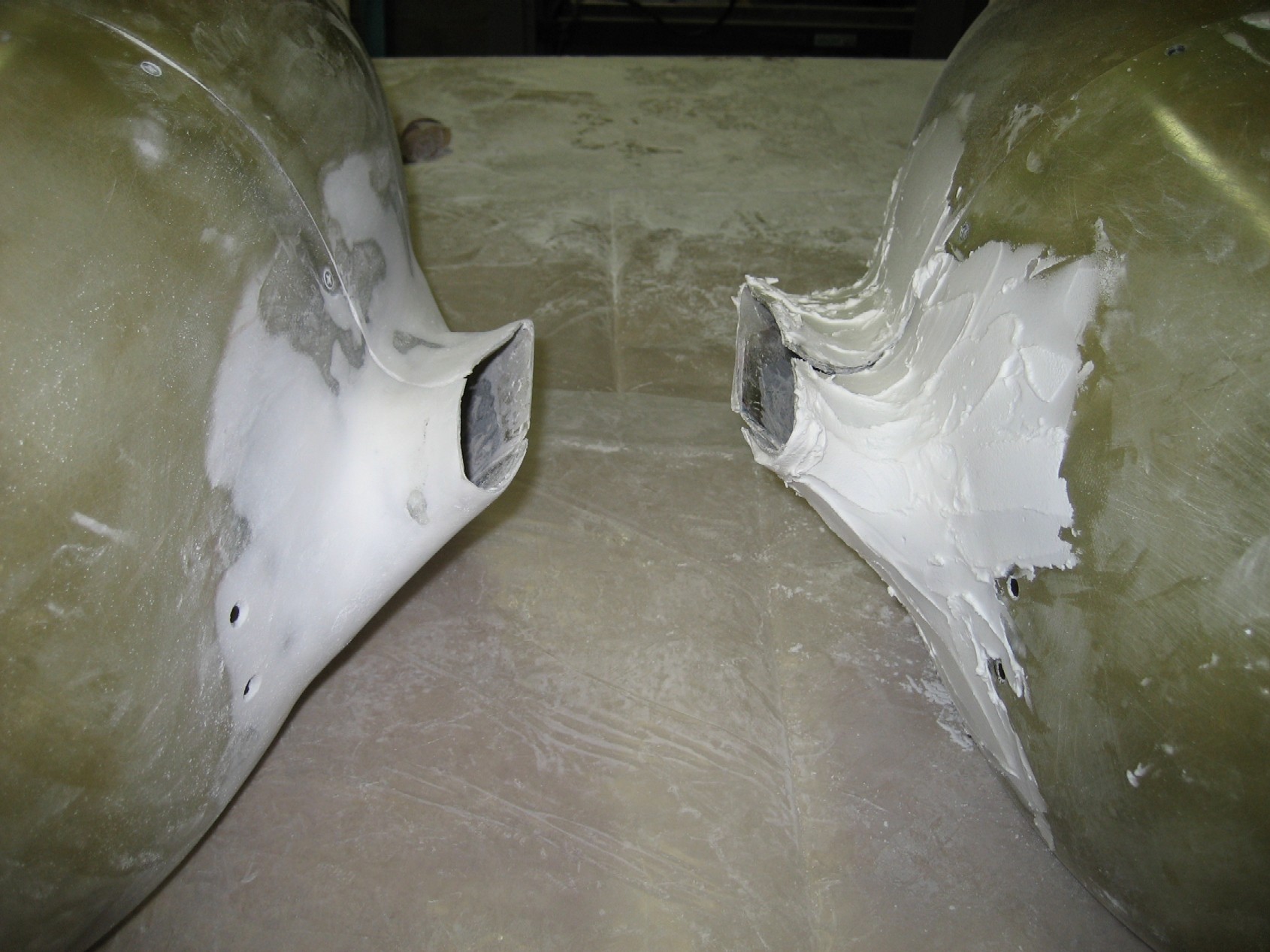
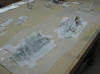
 E
The best way to fill all the voids in the fiberglass is to mix
up a very thick batch of epoxy and micro balloons. It
should be at thick as cake icing so it doesn't sag when you
butter it on. I used two pumps of West System's epoxy
for each wheel pant. When mixed with the micro balloons
this was just enough to cover the front and back of one wheel
pant. Once the stuff hardens I used sand paper wrapped
around a section of old ax handle and a flat sander to sand it
smooth. One wheel pant took about an hour and a half to
get it to the stage you see in this photo. Once sanded
they will be covered in straight epoxy to fill any pin holes
and make them ready for painting. (5/28/08) E
The best way to fill all the voids in the fiberglass is to mix
up a very thick batch of epoxy and micro balloons. It
should be at thick as cake icing so it doesn't sag when you
butter it on. I used two pumps of West System's epoxy
for each wheel pant. When mixed with the micro balloons
this was just enough to cover the front and back of one wheel
pant. Once the stuff hardens I used sand paper wrapped
around a section of old ax handle and a flat sander to sand it
smooth. One wheel pant took about an hour and a half to
get it to the stage you see in this photo. Once sanded
they will be covered in straight epoxy to fill any pin holes
and make them ready for painting. (5/28/08) |
| |
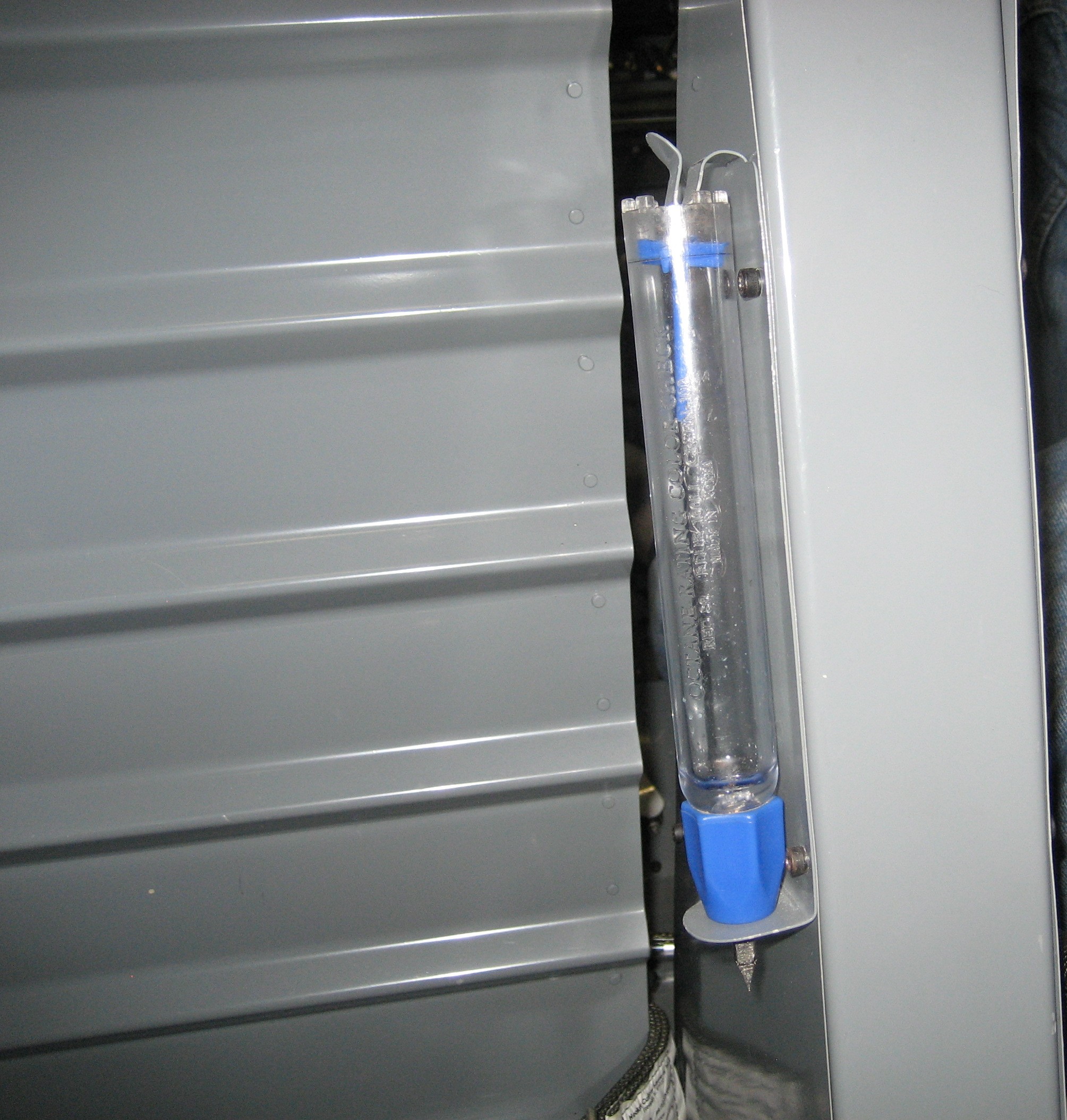
  F In an effort to keep my
plane as light as possible, I never installed pockets of any
type. This worked out great, until I realized that the
only place to store the fuel sampler was in my tool bag.
This was OK but there are just sometimes when I don't want
that in the back. The question came where to store the
fuel sampler, to which the answer was to make a simple bracket
out of some scrap aluminum and screw it to the flap motor
brace, behind the pilot seat. (11/12/08)
F In an effort to keep my
plane as light as possible, I never installed pockets of any
type. This worked out great, until I realized that the
only place to store the fuel sampler was in my tool bag.
This was OK but there are just sometimes when I don't want
that in the back. The question came where to store the
fuel sampler, to which the answer was to make a simple bracket
out of some scrap aluminum and screw it to the flap motor
brace, behind the pilot seat. (11/12/08) |
| |
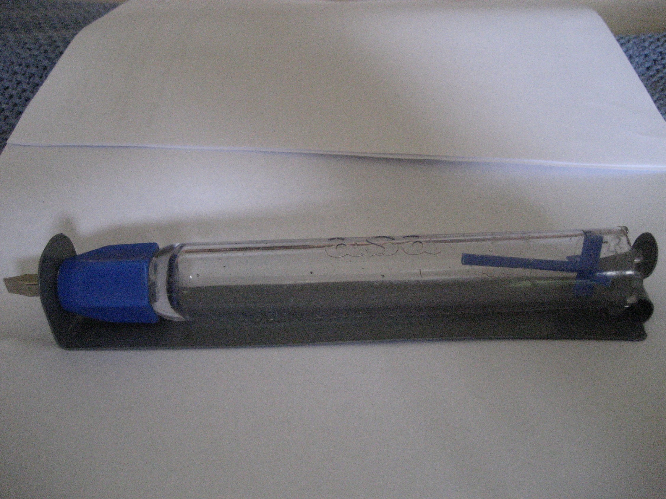
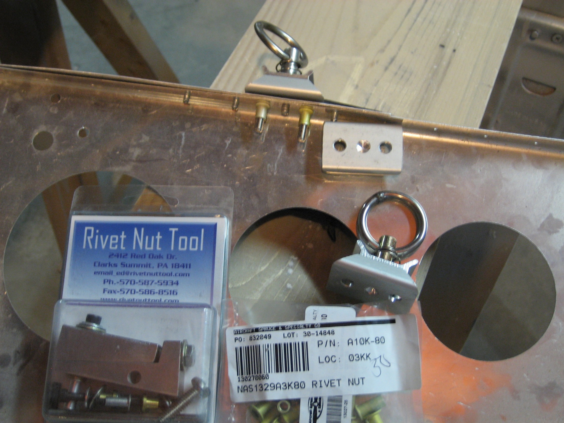
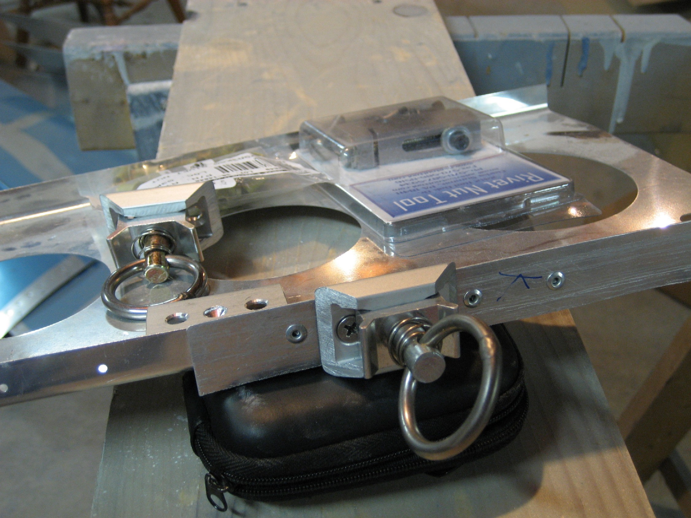
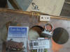  E
After flying for over 200 hours the need has arisen for some
tied downs in the baggage area. I found these little gems
for $7.95 from
Pit Posse. They are designed to hold motorcycles so
they should be strong enough to hold anything in my baggage
compartment. The picture on the left shows the mockup
floor board and rib I made for testing. Because the
rivets are already installed in my plane with pull rivets, I
had to drill a small relief in the bottom of the tie down
base. This allows it to be centered over an existing
rivet. The center to center distance on the base was
close but not an exact match to the rivet spacing, thus I
elected to use the base to space the riv-nuts between existing
rivets. E
After flying for over 200 hours the need has arisen for some
tied downs in the baggage area. I found these little gems
for $7.95 from
Pit Posse. They are designed to hold motorcycles so
they should be strong enough to hold anything in my baggage
compartment. The picture on the left shows the mockup
floor board and rib I made for testing. Because the
rivets are already installed in my plane with pull rivets, I
had to drill a small relief in the bottom of the tie down
base. This allows it to be centered over an existing
rivet. The center to center distance on the base was
close but not an exact match to the rivet spacing, thus I
elected to use the base to space the riv-nuts between existing
rivets.
Once in place, the base can be used as the drill
guide for the 1/4" hole required for the #10 keyed riv-nuts
(Pictured along with the riv-nut tool used to install them.
The pictures should be self explanatory. (11/12/08) |
| |
|
E
Previous Page |
.jpg)