|
  E
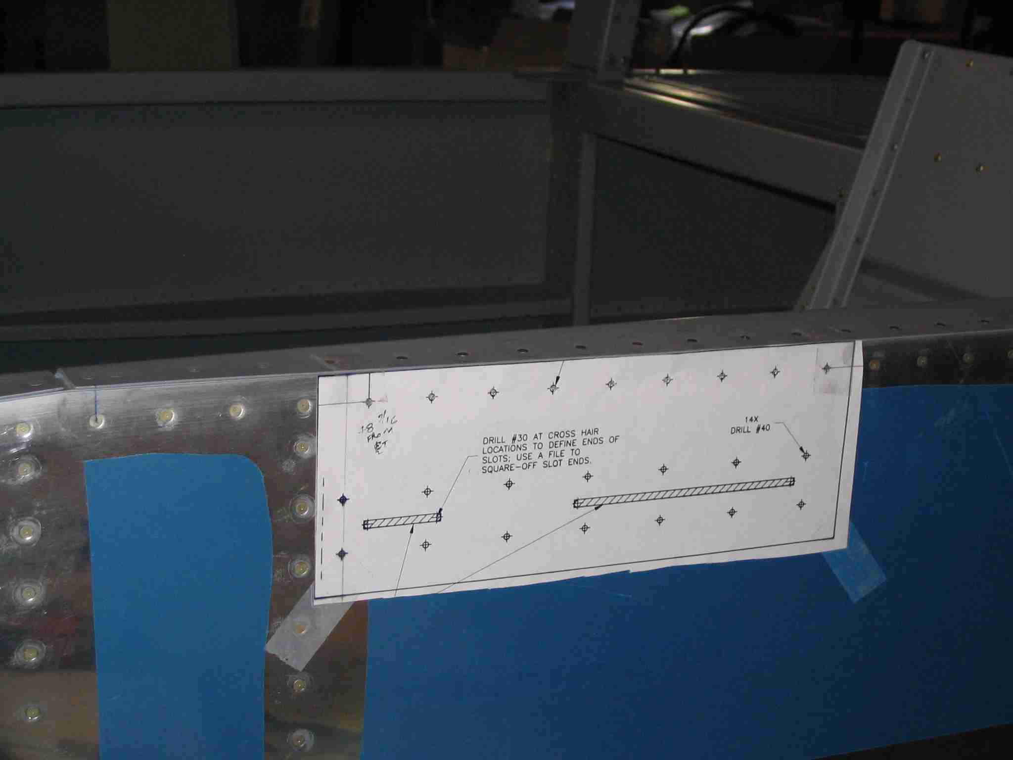
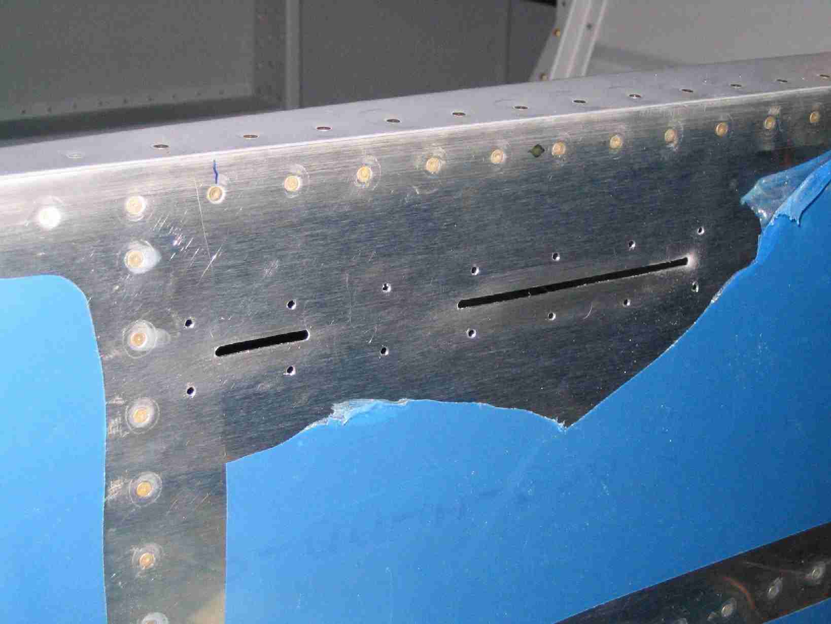
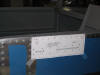
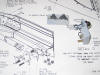
Cutting the slots for the canopy release was easy enough.
Cut the full size template out of the drawing, tape it on the
side of the airplane, center punch the holes, drill and cut.
I am not a big fan of using a Dremel but this was a great
application for it.
(5/1/06) E
Cutting the slots for the canopy release was easy enough.
Cut the full size template out of the drawing, tape it on the
side of the airplane, center punch the holes, drill and cut.
I am not a big fan of using a Dremel but this was a great
application for it.
(5/1/06) |
| |
|
  F
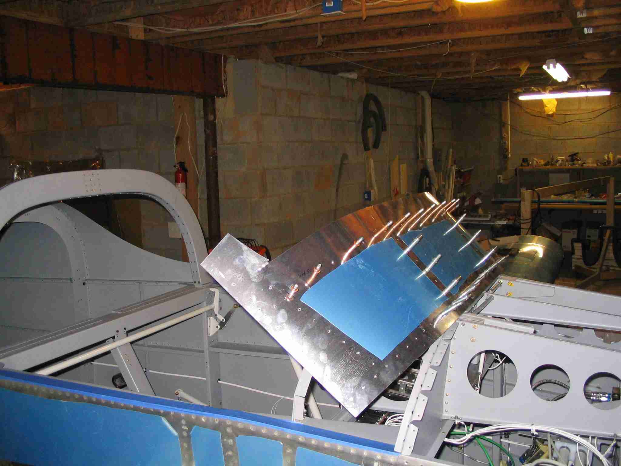
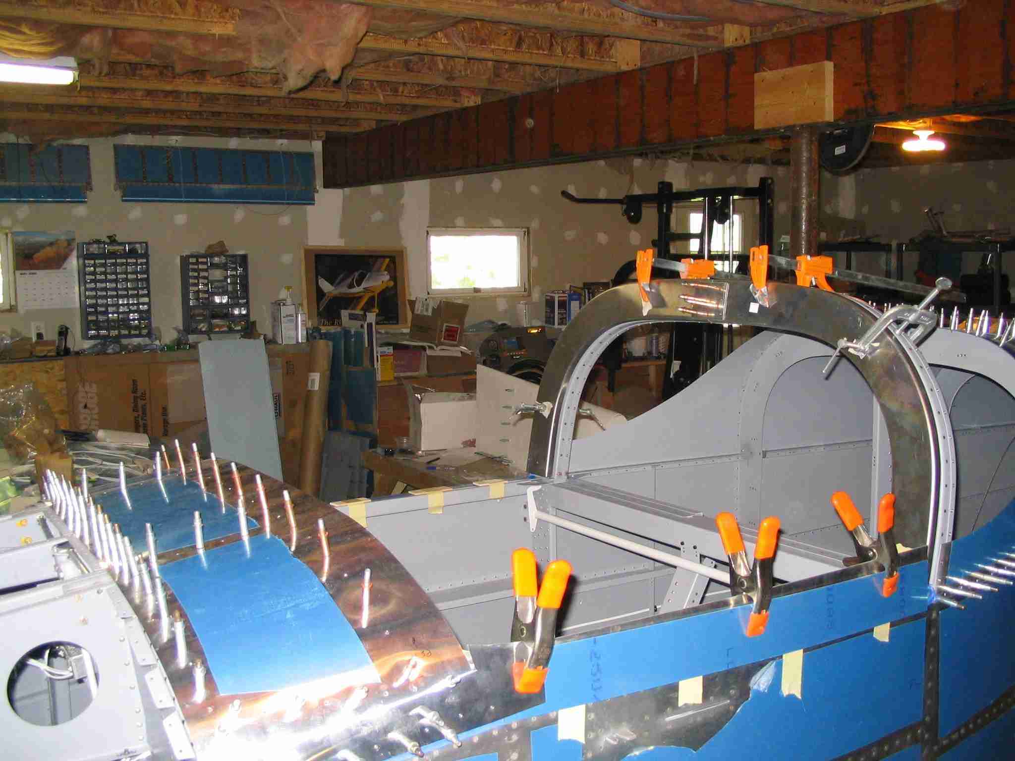
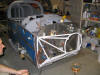
A lot of work has been accomplished since my last post.
The canopy frame is fitted and riveted together. Nothing
difficult here, just follow the directions. Next up will
be to remove the wings and fit the canopy aka "The Big Cut".
Over Memorial Day weekend I helped a friend cut his canopy, ok
I really just watched, and it doesn't look that difficult.
If you hear me scream, you know the thing cracked while
cutting mine. You will also notice that the canopy
release has been cut, fitted, and installed. Once again,
nothing difficult, just follow the instructions.
(5/31/06) F
A lot of work has been accomplished since my last post.
The canopy frame is fitted and riveted together. Nothing
difficult here, just follow the directions. Next up will
be to remove the wings and fit the canopy aka "The Big Cut".
Over Memorial Day weekend I helped a friend cut his canopy, ok
I really just watched, and it doesn't look that difficult.
If you hear me scream, you know the thing cracked while
cutting mine. You will also notice that the canopy
release has been cut, fitted, and installed. Once again,
nothing difficult, just follow the instructions.
(5/31/06) |
| |
|
 E
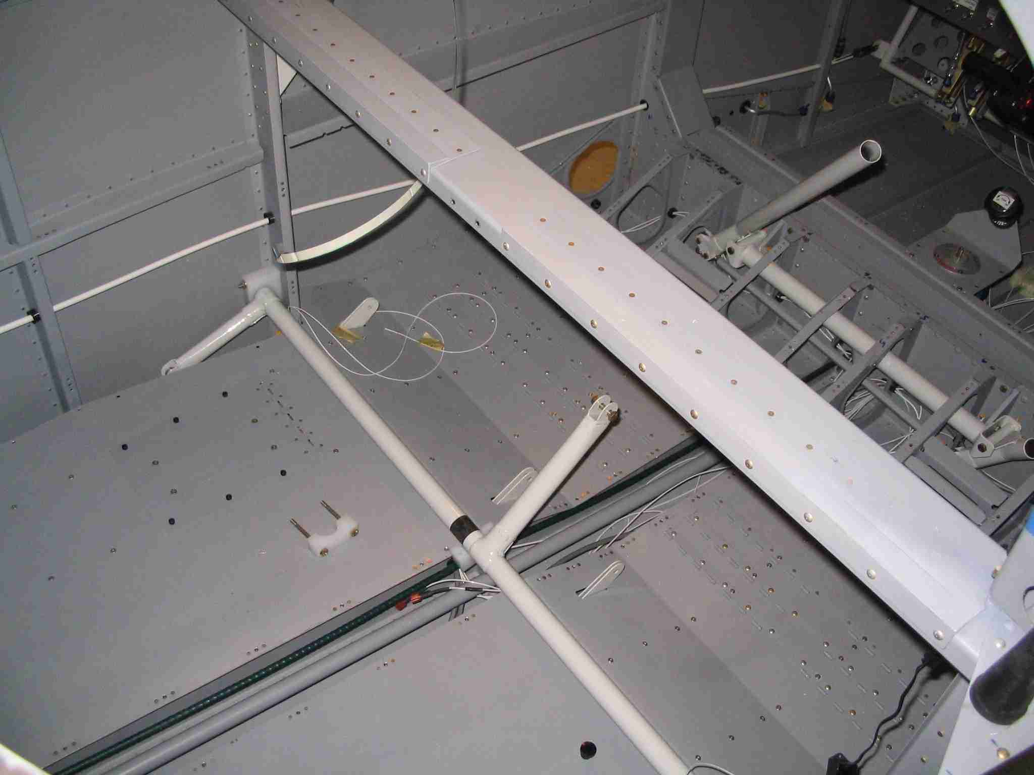
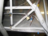
This is a shot of where I placed the Outside Air Temperature
(OAT) probe for the Dynon EFIS. This will be protected
under the empennage fairing.
(6/3/06) E
This is a shot of where I placed the Outside Air Temperature
(OAT) probe for the Dynon EFIS. This will be protected
under the empennage fairing.
(6/3/06) |
| |
|
 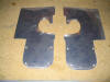 F
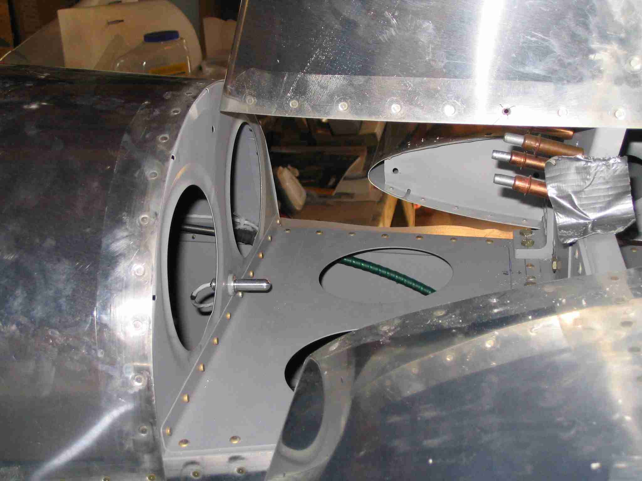
The access plate under the HS is very limited. Jeff
Bordelon came up with the idea of extending the access cover
upward and cutting the fiberglass faring short. There
are some detailed pictures on
Jeff's
site. The picture on the left are the cover plates
and the right picture is the right cover plate installed.
(6/3/06) F
The access plate under the HS is very limited. Jeff
Bordelon came up with the idea of extending the access cover
upward and cutting the fiberglass faring short. There
are some detailed pictures on
Jeff's
site. The picture on the left are the cover plates
and the right picture is the right cover plate installed.
(6/3/06) |
| |
|
  E
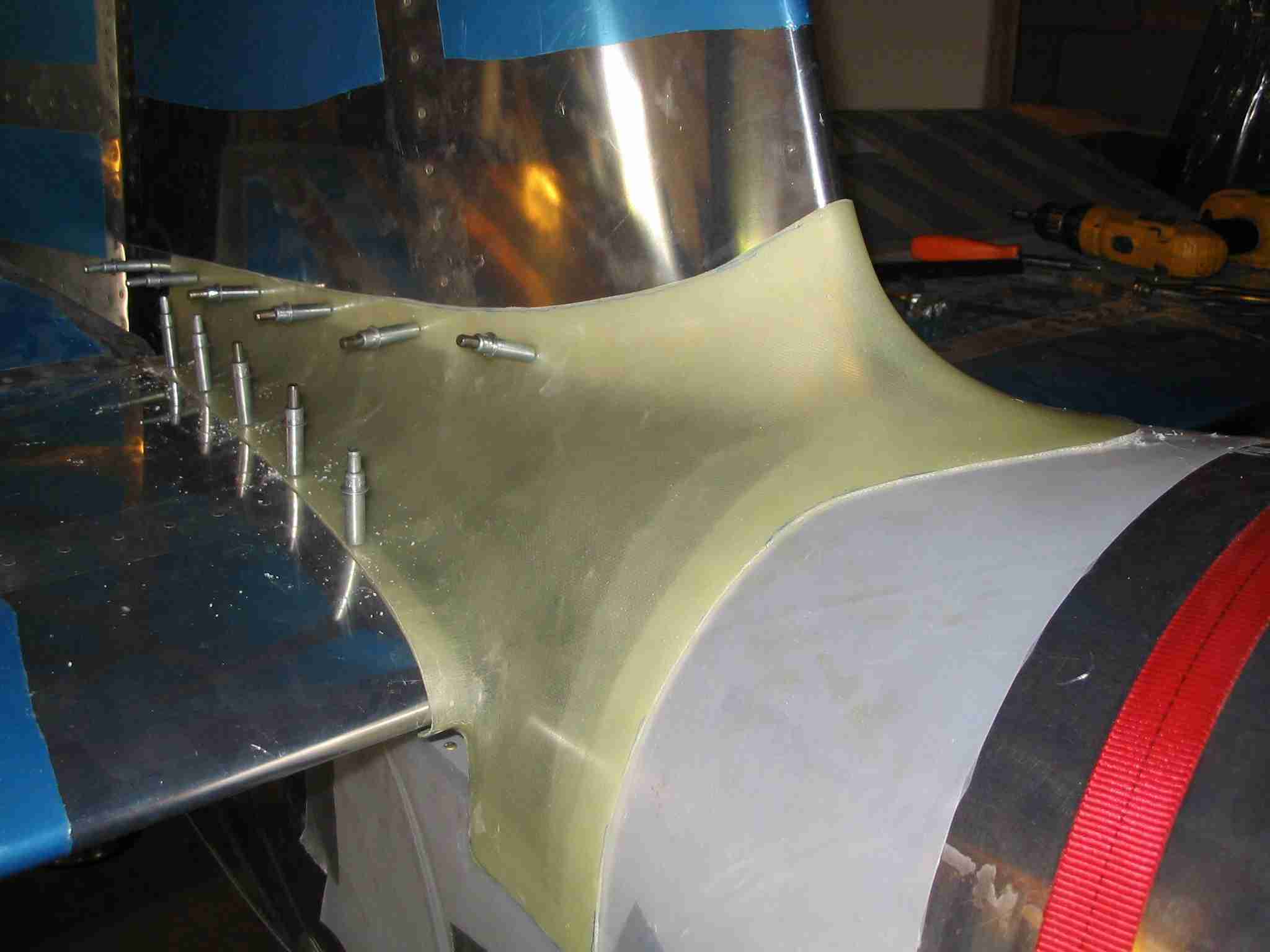
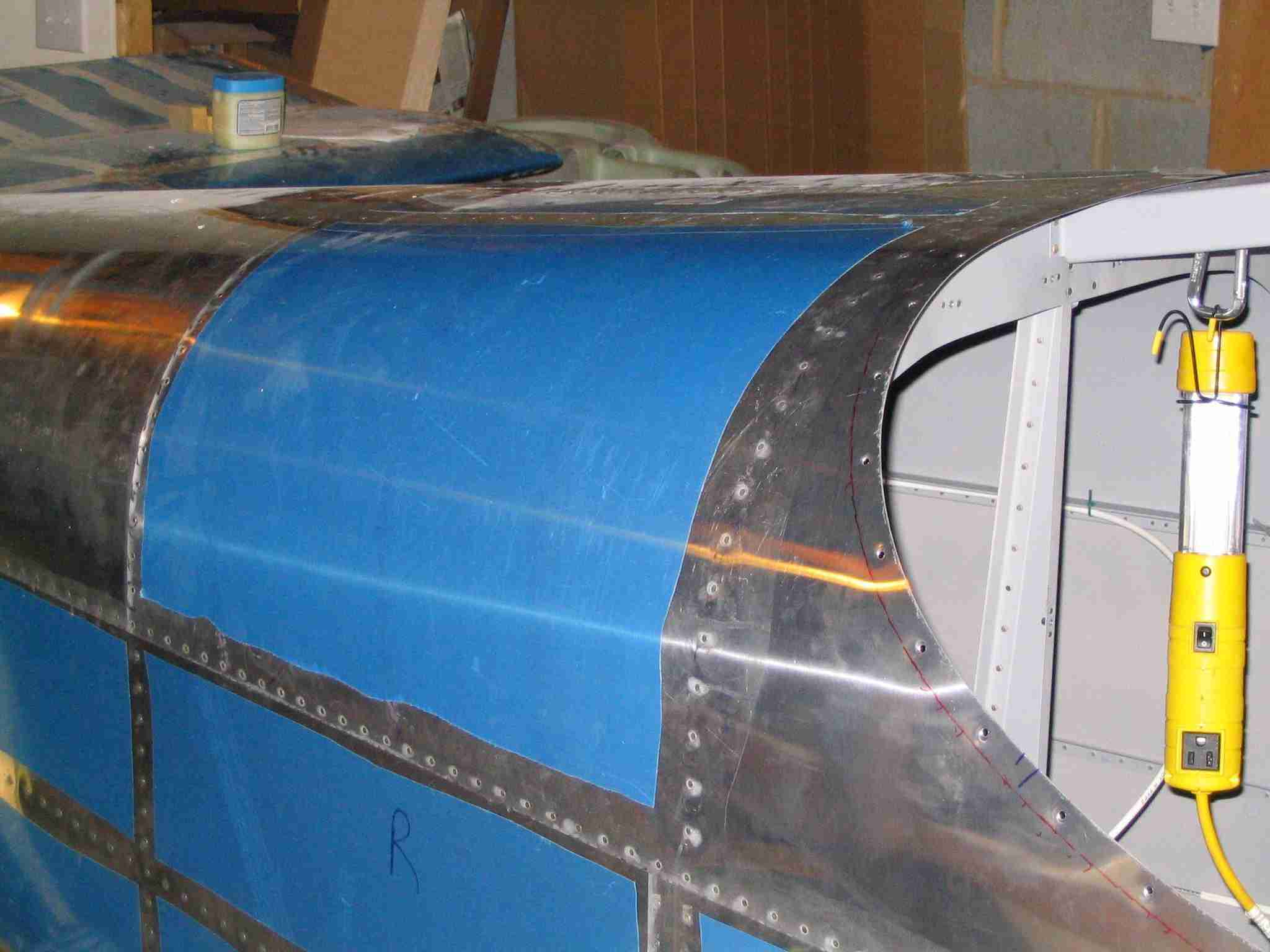
After hearing how poorly the fairings from Van's fit, I was
expecting a good bit of trouble. Once they were trimmed
along the very faint part line, they fit surprisingly well.
(6/3/06) E
After hearing how poorly the fairings from Van's fit, I was
expecting a good bit of trouble. Once they were trimmed
along the very faint part line, they fit surprisingly well.
(6/3/06) |
| |
|
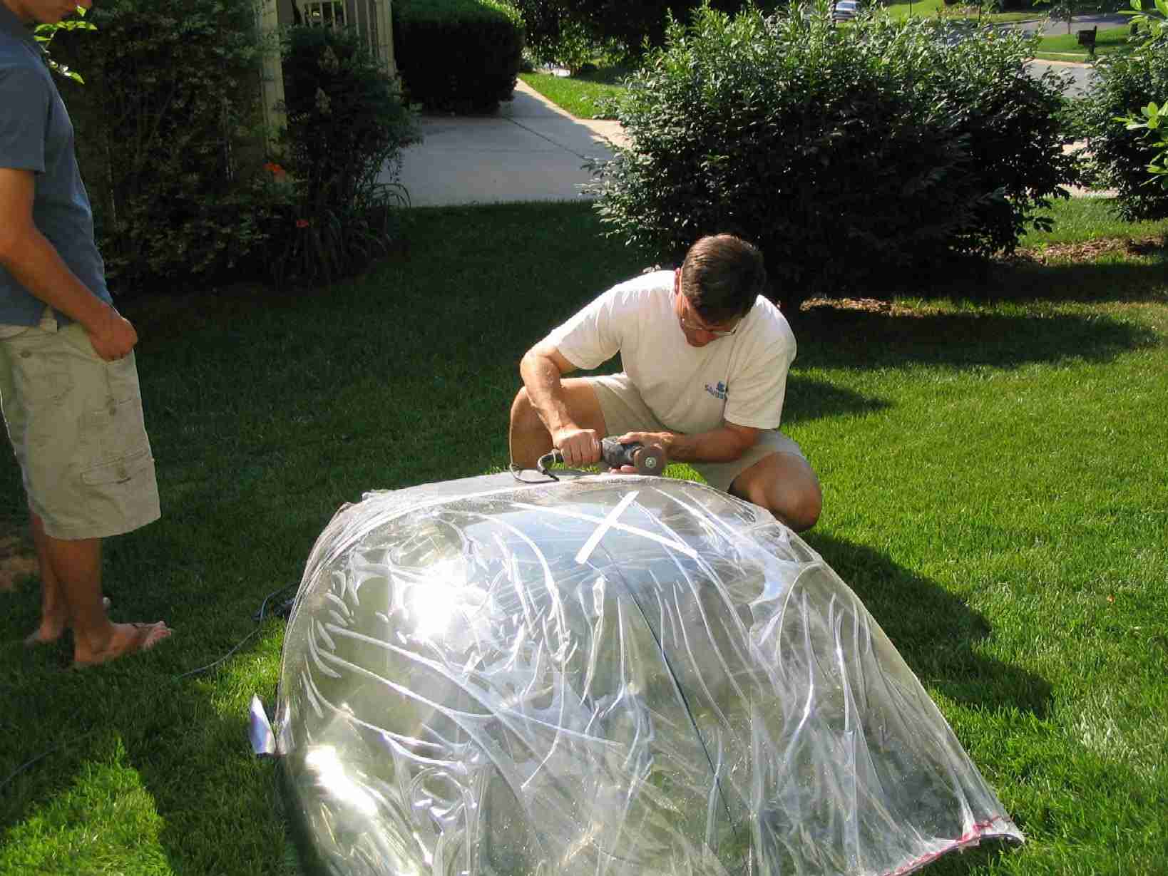
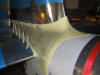
  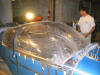 F
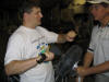
I called Tad Sargent at work around 3pm to talk RV's and
mentioned I was ready to make "The BIG Cut". He was kind
enough to go home, change, and come back with his son and
riveting partner TJ. After measuring and marking the
canopy we took it outside to warm in the sun. An hour
after he arrived we were sipping some bourbon and admiring the
canopy. I owe Tad a big thanks for the help! (6/6/06) F
I called Tad Sargent at work around 3pm to talk RV's and
mentioned I was ready to make "The BIG Cut". He was kind
enough to go home, change, and come back with his son and
riveting partner TJ. After measuring and marking the
canopy we took it outside to warm in the sun. An hour
after he arrived we were sipping some bourbon and admiring the
canopy. I owe Tad a big thanks for the help! (6/6/06) |
| |
|
 E
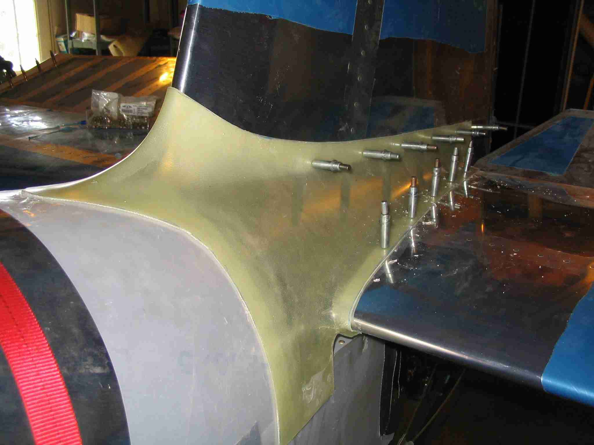
The evening was spent trimming the canopy, as will the next
several nights. However, I peeled the empennage faring
off and set it aside. Now that it has been fitted I will
sand off the excess epoxy to obtain a custom fit.
(6/7/06) E
The evening was spent trimming the canopy, as will the next
several nights. However, I peeled the empennage faring
off and set it aside. Now that it has been fitted I will
sand off the excess epoxy to obtain a custom fit.
(6/7/06) |
| |
|
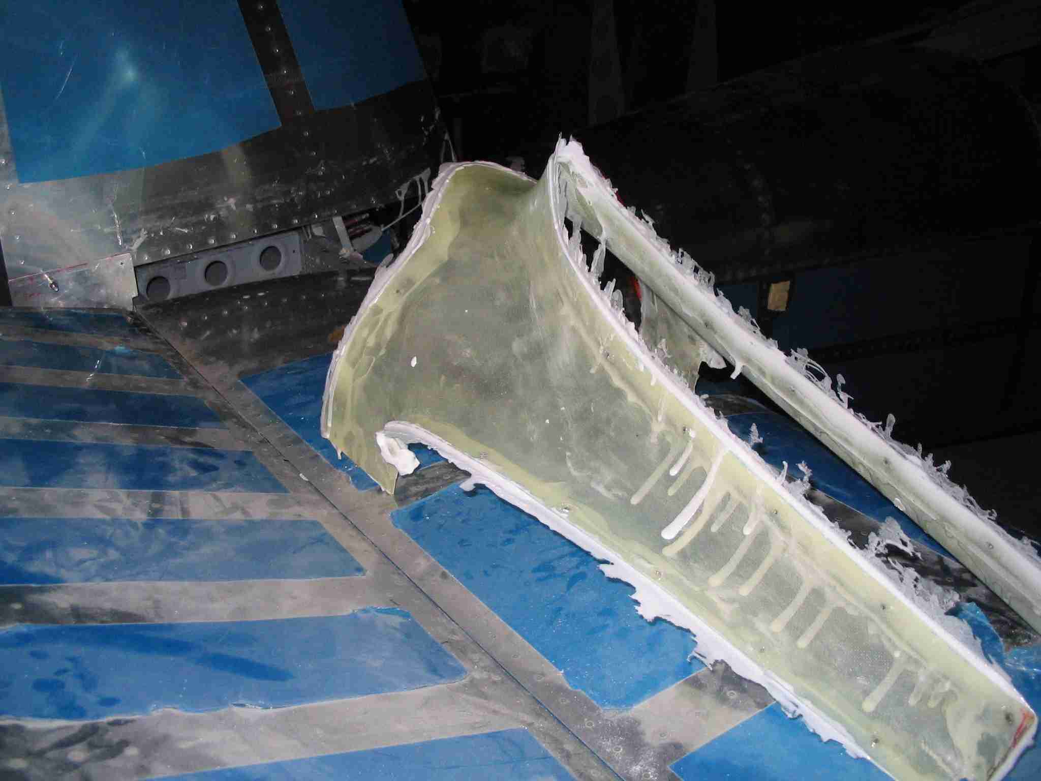
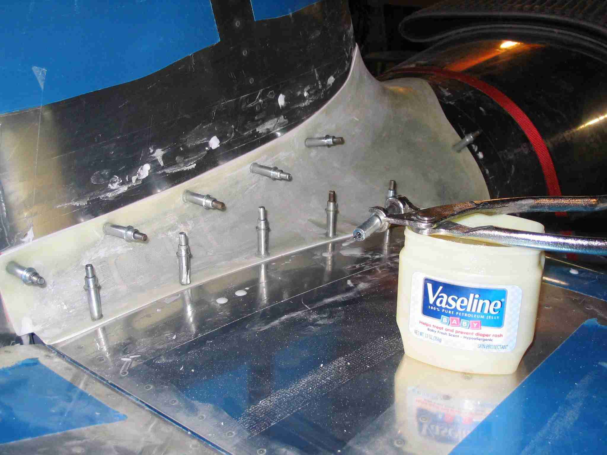
 F
The empennage fairing will be completed tomorrow after I sand
it with some extra fine sand paper, probably around 220 grit.
To keep the epoxy / micro-balloon mix from sticking to the
clecos I dipped them in vaseline. The aluminum was
protected by layers of clear packing tape. I found out
after starting this that the trick is to make the epxoy /
micro-balloon mix as thick as peanut butter and then smear it
between the aluminum and fiberglass faring with your finger.
Once this is done, sanding it is straight forward. Using
100 grit and a rubber sanding block made it go very fast.
Of course the block was not used when sanding the compound
curves. F
The empennage fairing will be completed tomorrow after I sand
it with some extra fine sand paper, probably around 220 grit.
To keep the epoxy / micro-balloon mix from sticking to the
clecos I dipped them in vaseline. The aluminum was
protected by layers of clear packing tape. I found out
after starting this that the trick is to make the epxoy /
micro-balloon mix as thick as peanut butter and then smear it
between the aluminum and fiberglass faring with your finger.
Once this is done, sanding it is straight forward. Using
100 grit and a rubber sanding block made it go very fast.
Of course the block was not used when sanding the compound
curves.
Once the edges were fitted it was
time to fill all the "pin holes" in the fiberglass. In
checking with our EAA chapter's plastic plane builders and
some of the RV builder's forums I came up with the following
ways to accomplish this.
1. Do nothing and just paint the
thing. Let the paint shop fix it.
2. Squeegee on pure epoxy mix and
sand off the high points
3. Squeegee on a mix of epoxy & micro
balloons and sand of the high points
4. Spray on "sandable primer", sand
off, repeat until holes are filled.
5. Mix epoxy 50/50 with Acetone,
brush on and paint over it. Some light sanding may be
required.
6. Fill all the holes with
lightweight aircraft dent filler.
There are advantages and
disadvantages to each of those methods. It will be up to
you to research what will work best for you. Being the
loggerhead that I am, I started with #2 and moved up to #3 and
may progress to #5.
I skipped #4 because of my fear of
compatibility issues with my final paint, whatever that may
be.
So far I have not found working with
fiberglass to be difficult and the best part is if you mess
something up, you can patch it and move on. In that
regard, it is kind of like working with drywall.
Check out the rudder page for some
more tips on working with fiberglass. Note, there are
some very good RV web sites out there that detail what
fiberglass supplies will be required, thus I found no need to
duplicate such lists. (6/24/06) |
| |
|
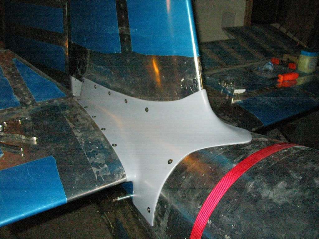
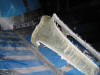
 E
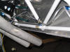
The empennage fairing is finished! Or so I think.
Man, there are a lot of plate nuts holding this thing in
place. The red strap you see is to keep the fuselage
from tilting forward in its cradle. (7/1/06) E
The empennage fairing is finished! Or so I think.
Man, there are a lot of plate nuts holding this thing in
place. The red strap you see is to keep the fuselage
from tilting forward in its cradle. (7/1/06) |
| |
|
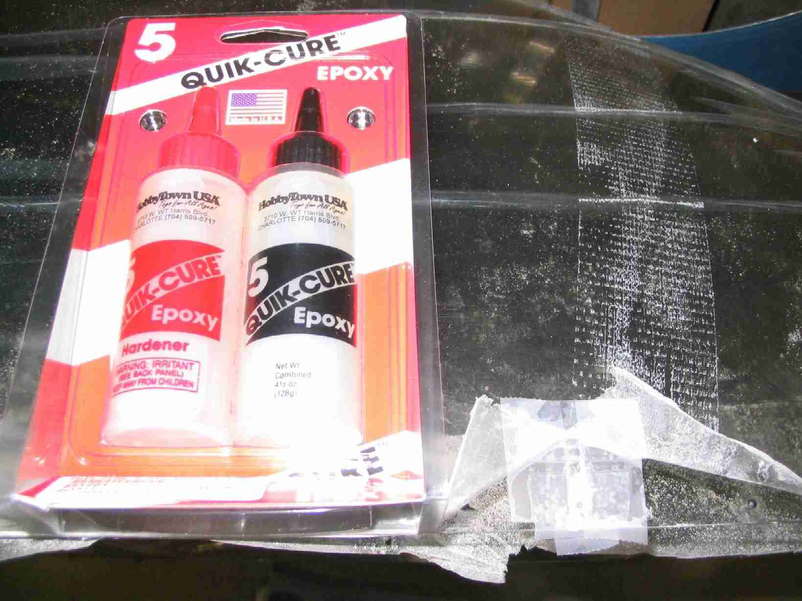
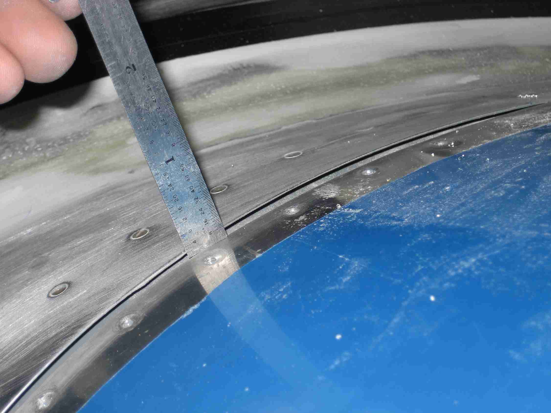
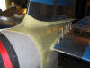
  F
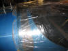
While very carefully drilling the canopy I managed to create a
small stress crack, much to my dismay. You can see the
1/8" stop drill hole just above the right cleco. I used
Cyanoacralate to glue the crack and epoxy to fill the stop
drill hole. Both of these I found at Hobby Town. F
While very carefully drilling the canopy I managed to create a
small stress crack, much to my dismay. You can see the
1/8" stop drill hole just above the right cleco. I used
Cyanoacralate to glue the crack and epoxy to fill the stop
drill hole. Both of these I found at Hobby Town.
I believe the reason the canopy
cracked was that I was using my halogen lights to heat the
canopy while drilling it and the lights may have heated it
unevenly, thus causing some stress. The drill bit I was
using was the correct Plexiglas drill bit. Next up will
be enlarging the holes and countersinking them. If that
goes bad, it will be time to open my wallet for a new canopy.
(7/12/06) |
| |
|
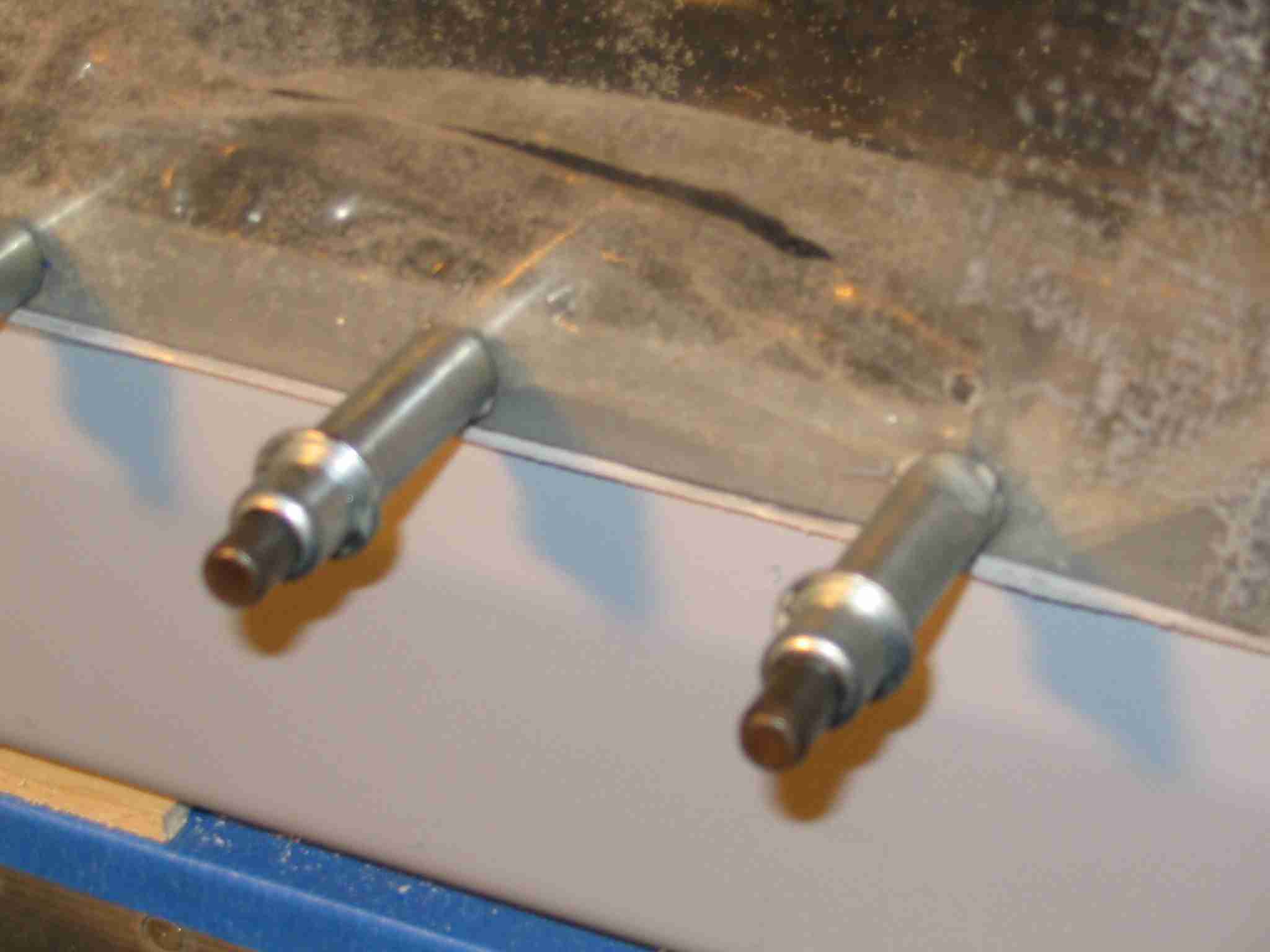
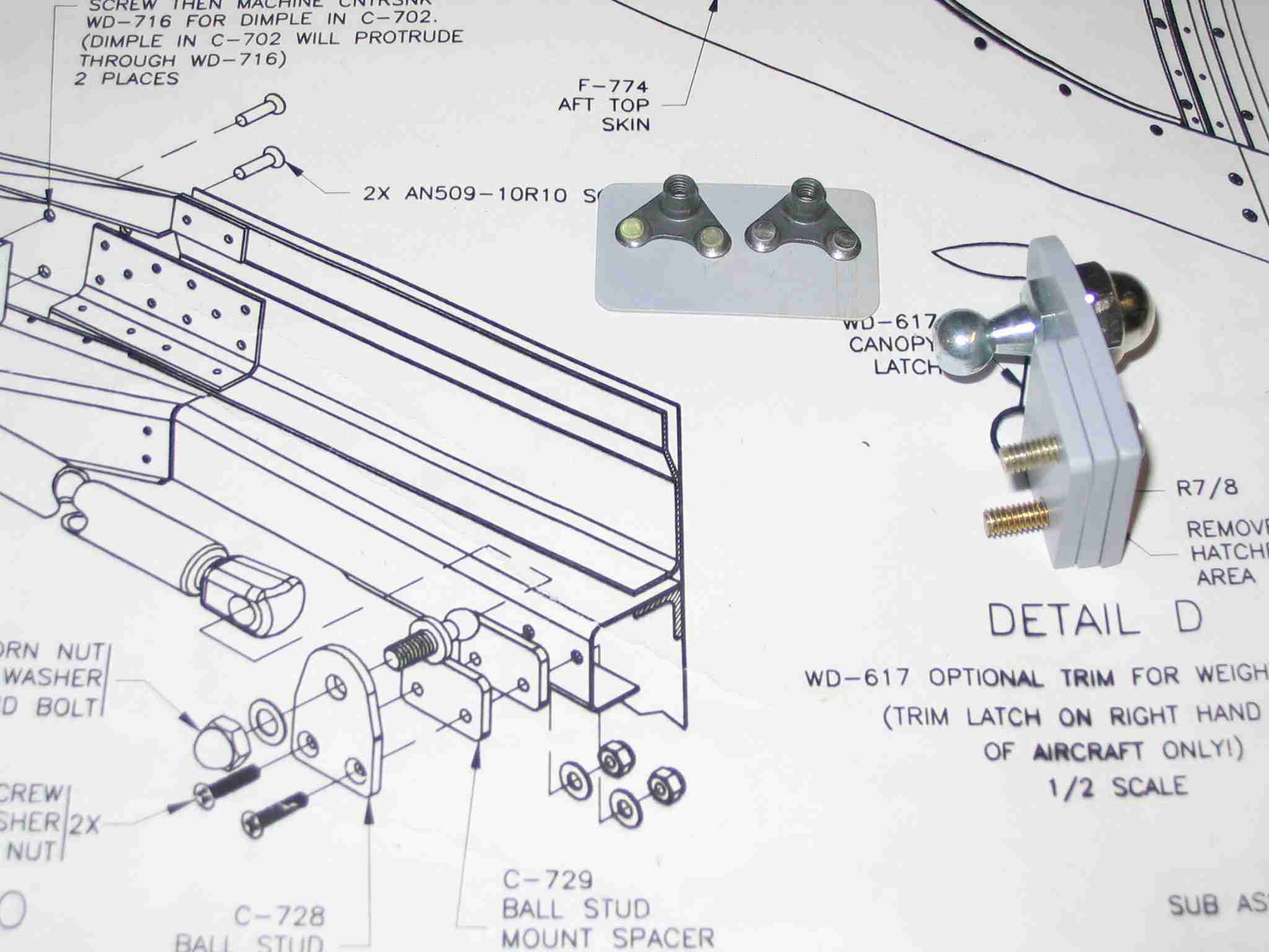
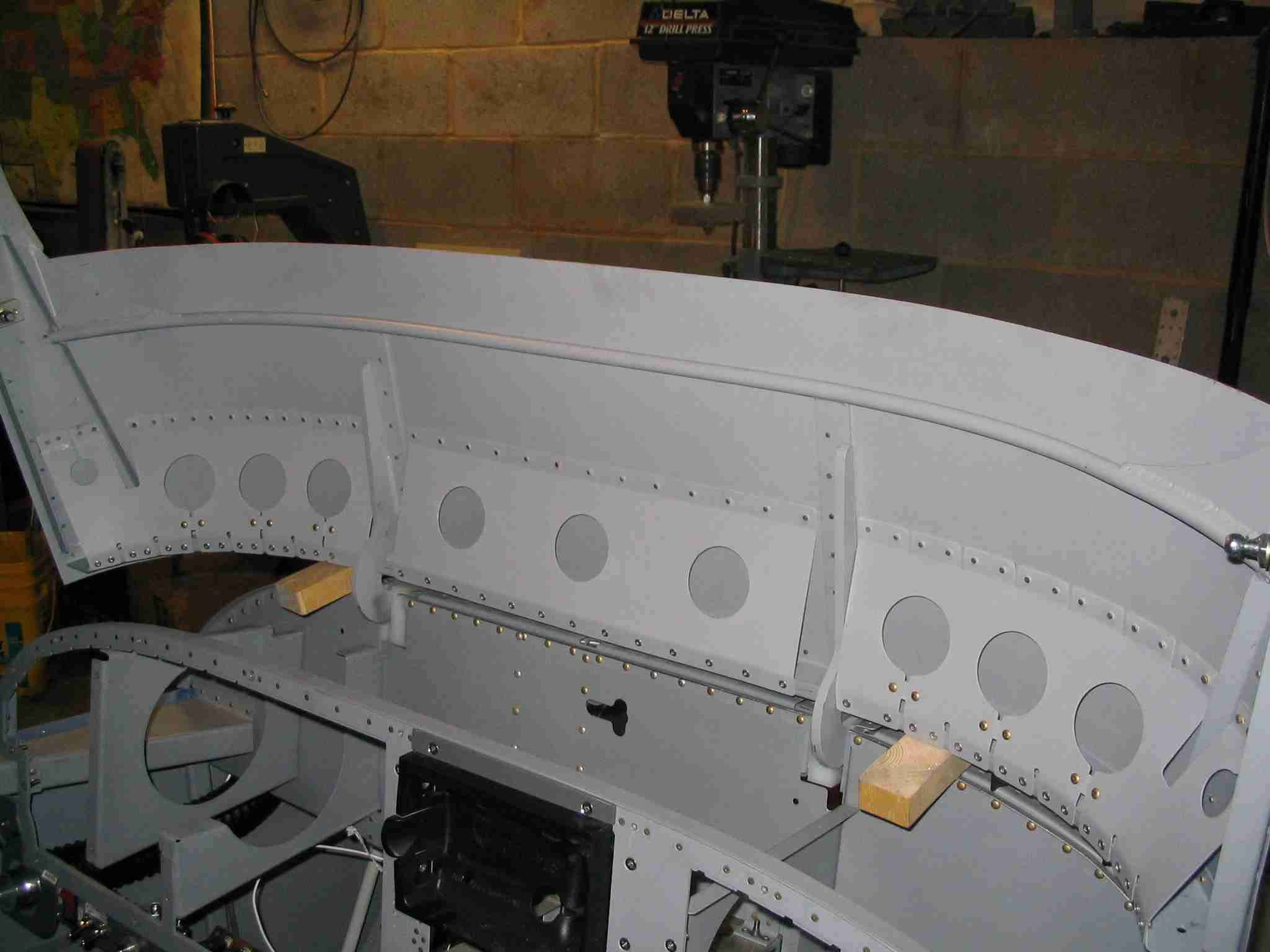
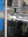
  E
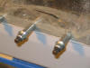
I have no idea who came up with this idea but my friend
Radomir passed it along to me. The plans call for two
small nuts to hold the lift strut ball in place. Well, I
don't know about you but my hands will not fit up under the
rail to start the nuts, not to mention there is no way I could
ever get a wrench on those nuts. Radomir's suggestion
was to put two plate nuts on a piece of aluminum and use that
in place of the nuts. (See the picture on the left.) E
I have no idea who came up with this idea but my friend
Radomir passed it along to me. The plans call for two
small nuts to hold the lift strut ball in place. Well, I
don't know about you but my hands will not fit up under the
rail to start the nuts, not to mention there is no way I could
ever get a wrench on those nuts. Radomir's suggestion
was to put two plate nuts on a piece of aluminum and use that
in place of the nuts. (See the picture on the left.)
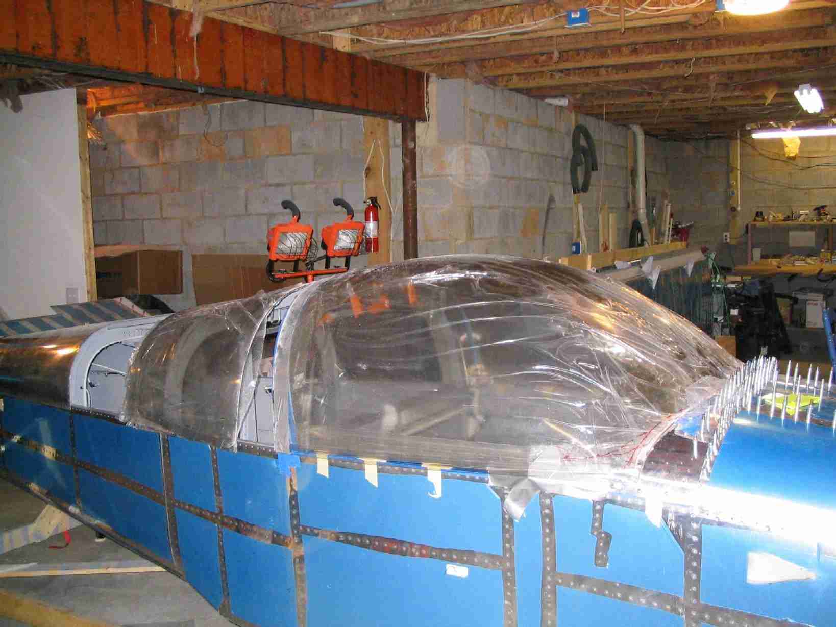
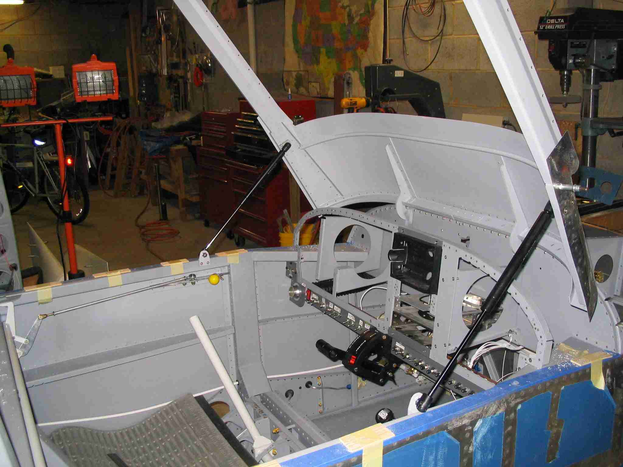
The second picture is my canopy frame
being held open by the lift struts for the first time.
Next will be to add the stiffeners to the underside of the
canopy frame. Once that is finished I will install the
canopy. (7/22/06) |
| |
|
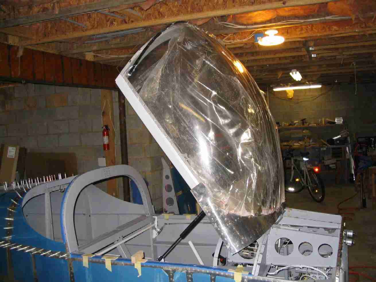
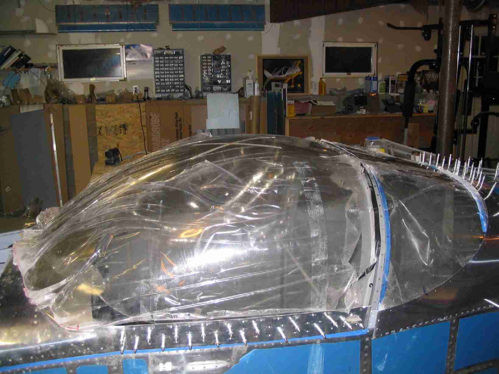
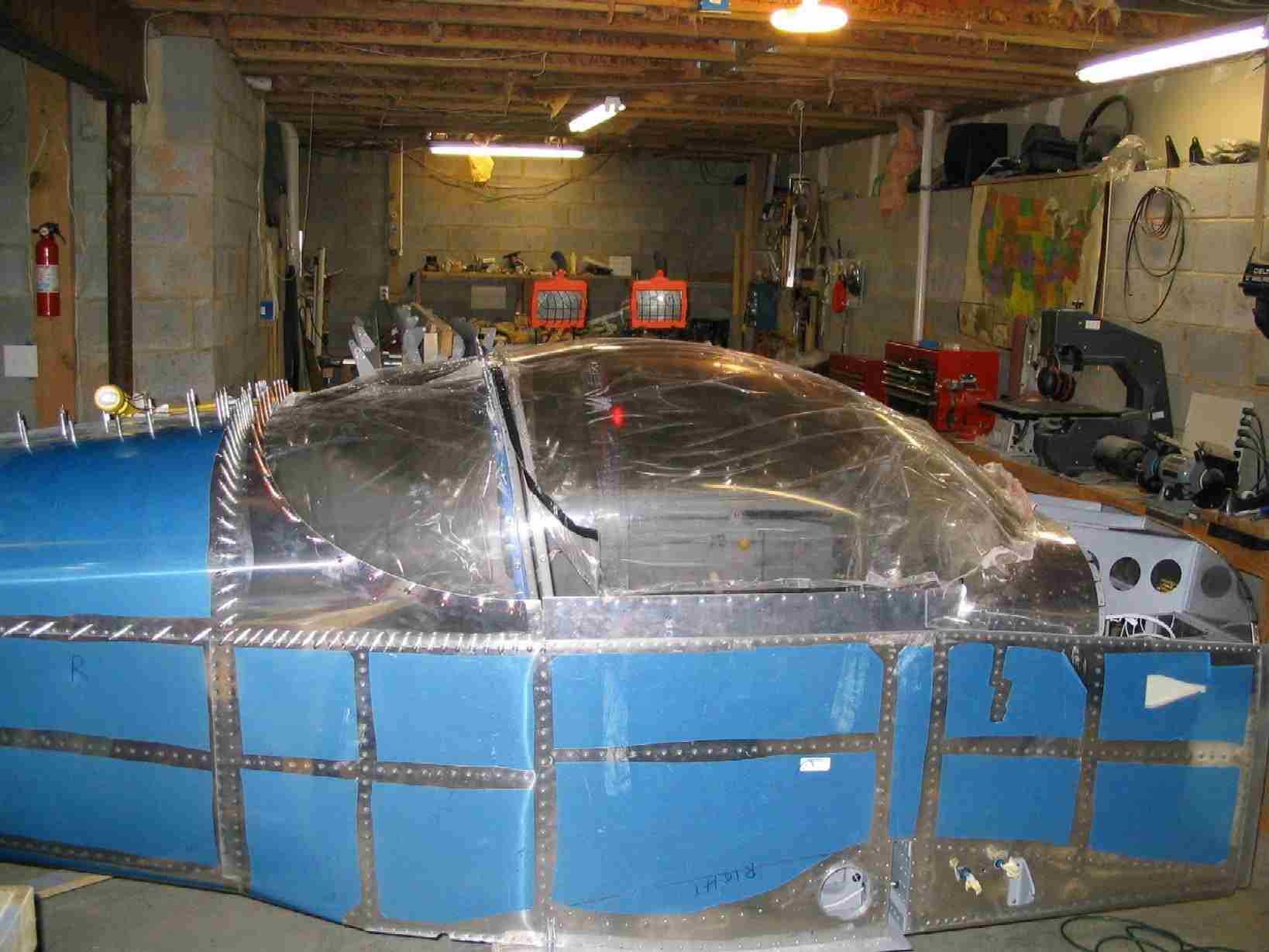
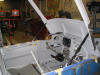
  F
Made a lot of progress today. Fitted, matched drilled,
alodined, painted, and rived the tip-up stiffeners in place.
Then started fitting the canopy. This is the first time
the tip-up frame has been opened with the canopy installed.
In a day or two I might actually get to start fiberglassing
that thing in place. (7/23/06) F
Made a lot of progress today. Fitted, matched drilled,
alodined, painted, and rived the tip-up stiffeners in place.
Then started fitting the canopy. This is the first time
the tip-up frame has been opened with the canopy installed.
In a day or two I might actually get to start fiberglassing
that thing in place. (7/23/06) |
| |
|
 E
Boy do I ever feel like I'm making progress now! I
messed up the left canopy skirt and had to order a
replacement. No big deal, at this point I have a growing
pile of dead parts so what's one more. The plans calls
out hole spacing for the skirt but they were useless since I
had already drilled the canopy to the tip-up frame. What
I did was put a screw w/ a tenaman (sp?) washer in every other
hole to hold the canopy in place. Then the side skirt
was taped in place. Reaching in from the back side, I
drilled through the existing screw holes in the frame side and
canopy to the skirt. After drilling two holes I removed
the skirt, deburred and dimpled the holes and then screwed
them in place. This allowed me to finish drilling the
every other hole. When that was finished I once again
removed the side skirt, deburred and dimped the holes, removed
the screws and tenaman washers, and screwed the thing back in
place. Once again I reached in from the baggage
compartment and match drilled the remaining holes. After
that the skirt was removed once more and the pattern for the
rivet holes was laid out and drilled. It was then
reinstalled and the rivet holes were matched drilled through
the canopy frame. A lot of installing and removing but
the results were well worth the effort. (7/24/06) E
Boy do I ever feel like I'm making progress now! I
messed up the left canopy skirt and had to order a
replacement. No big deal, at this point I have a growing
pile of dead parts so what's one more. The plans calls
out hole spacing for the skirt but they were useless since I
had already drilled the canopy to the tip-up frame. What
I did was put a screw w/ a tenaman (sp?) washer in every other
hole to hold the canopy in place. Then the side skirt
was taped in place. Reaching in from the back side, I
drilled through the existing screw holes in the frame side and
canopy to the skirt. After drilling two holes I removed
the skirt, deburred and dimpled the holes and then screwed
them in place. This allowed me to finish drilling the
every other hole. When that was finished I once again
removed the side skirt, deburred and dimped the holes, removed
the screws and tenaman washers, and screwed the thing back in
place. Once again I reached in from the baggage
compartment and match drilled the remaining holes. After
that the skirt was removed once more and the pattern for the
rivet holes was laid out and drilled. It was then
reinstalled and the rivet holes were matched drilled through
the canopy frame. A lot of installing and removing but
the results were well worth the effort. (7/24/06) |
| |
|
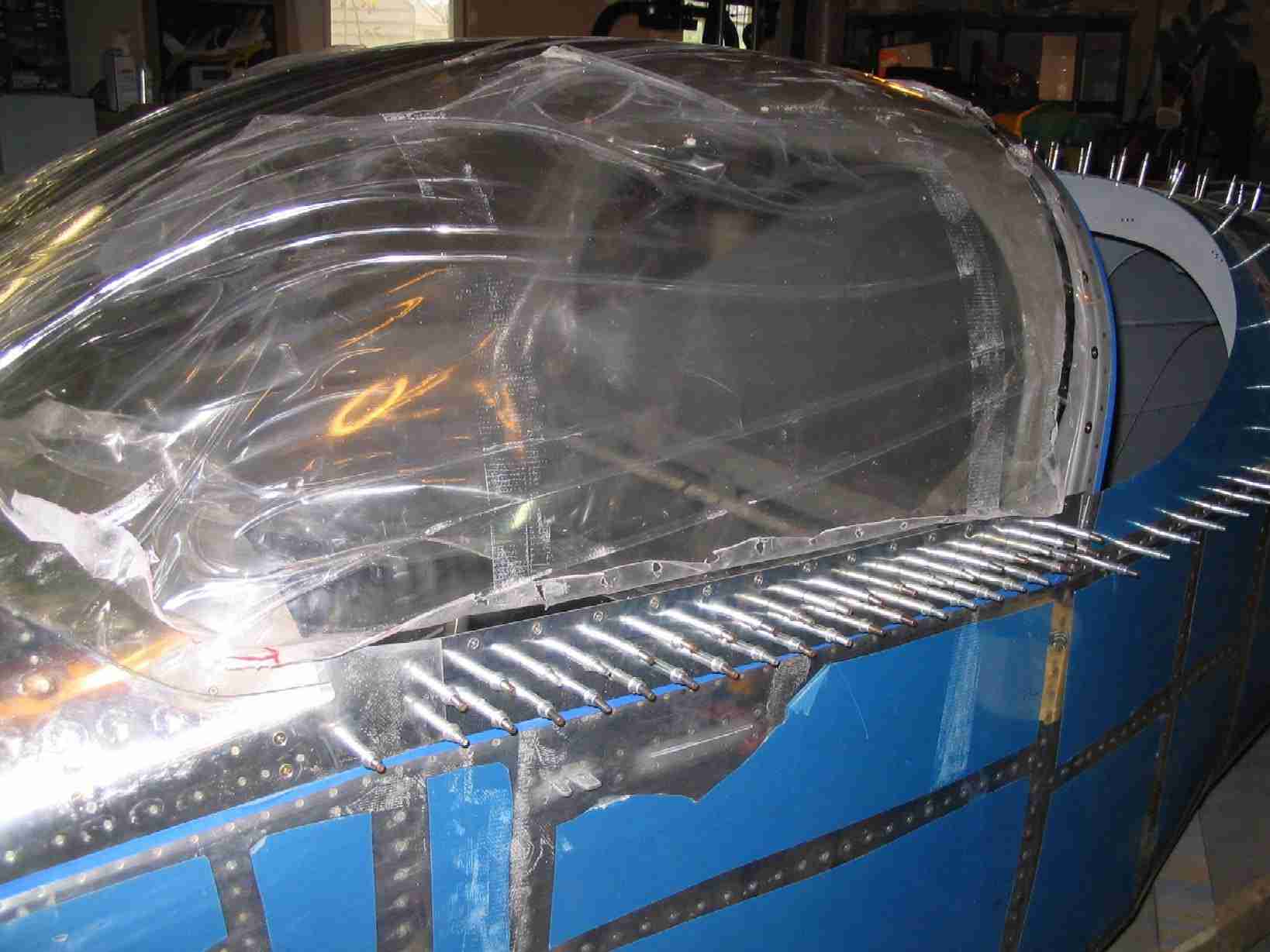
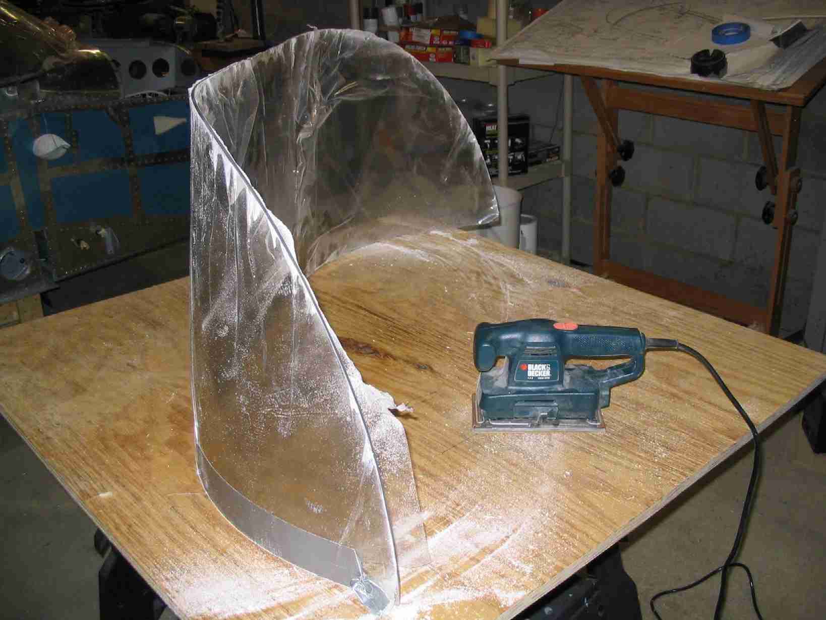
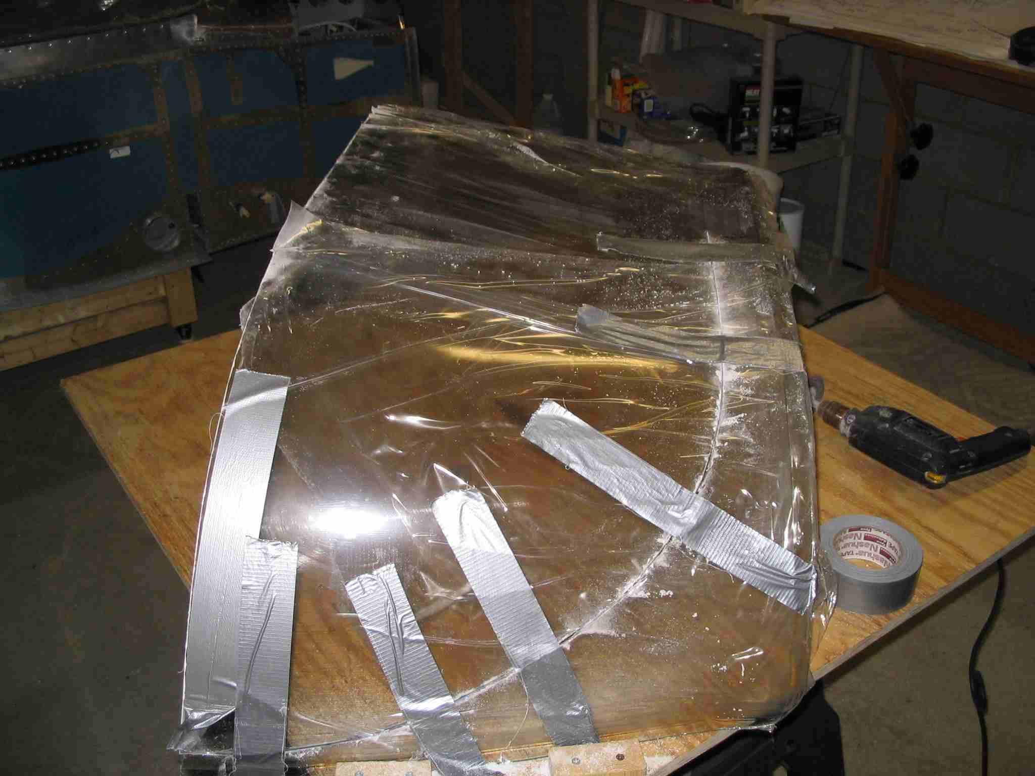
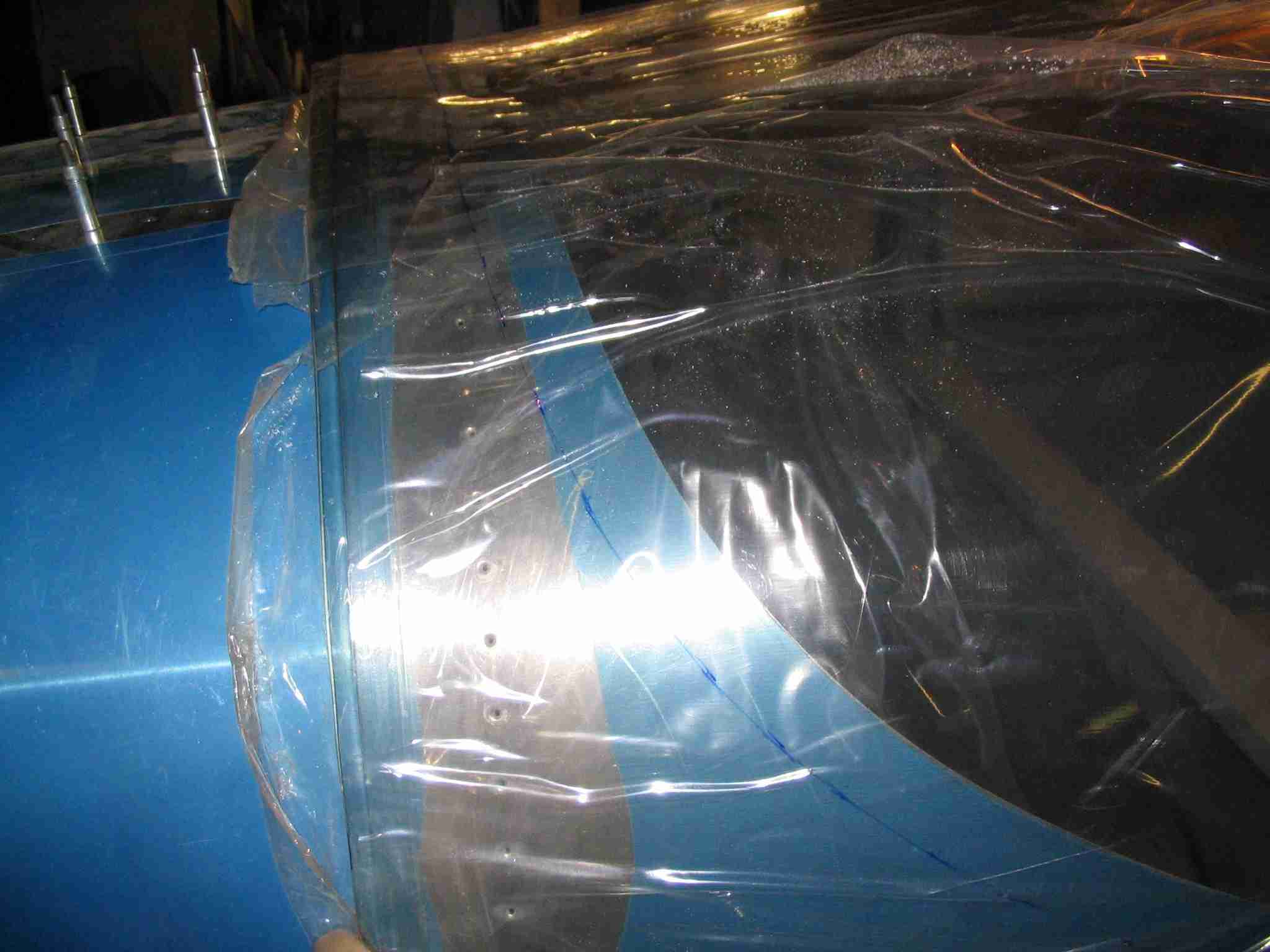
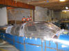
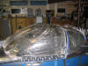
    F
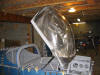
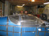
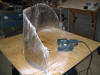
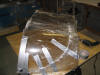
In two hours I measure, cut, and sanded the aft canopy.
The results were very close to the final cut. The 1/3
sheet Black & Decker vibrating sander with 100 grit paper
worked very well for removing any cut marks on the plexi.
Once the thing is fit to its final size, I will work down to
some very fine sand paper but for now, 100 grit will work.
The pictures from left to right are: Aft canopy set in place
and marked for cutting, the canopy being cut (note the tape to
hold it together and the blocks on the table to keep it from
spreading.), Aft canopy being sanded, and finally the aft
canopy section set in place. (7/25/06) F
In two hours I measure, cut, and sanded the aft canopy.
The results were very close to the final cut. The 1/3
sheet Black & Decker vibrating sander with 100 grit paper
worked very well for removing any cut marks on the plexi.
Once the thing is fit to its final size, I will work down to
some very fine sand paper but for now, 100 grit will work.
The pictures from left to right are: Aft canopy set in place
and marked for cutting, the canopy being cut (note the tape to
hold it together and the blocks on the table to keep it from
spreading.), Aft canopy being sanded, and finally the aft
canopy section set in place. (7/25/06) |
| |
|
 E
The aft skin was drilled with 1/8" holes where the screws will
go through the aft canopy. The aft canopy required some
minor trimming from Van's rough dimensions but all-in-all it
came out great. Some minor sanding is required before
drilling it to the roll bar and aft skin but I felt so lucky
to have a straight line and generally great fitting aft canopy
that I felt it was time to call it a day. (7/26/06) E
The aft skin was drilled with 1/8" holes where the screws will
go through the aft canopy. The aft canopy required some
minor trimming from Van's rough dimensions but all-in-all it
came out great. Some minor sanding is required before
drilling it to the roll bar and aft skin but I felt so lucky
to have a straight line and generally great fitting aft canopy
that I felt it was time to call it a day. (7/26/06)
Helpful update:
When I did this I elected to use #6 stainless steel tenamen
(sp?) washers on all the screws. My thinking was that
these will help distribute the stress of the screws a little
bit better than just a screw head in Plexiglas. Aircraft
Spruce sells the washers under part number 04-00397.
(10/8/06) |
| |
|
 F
The aft canopy was match drilled with the help of my wonderful
wife. Didn't have much time to work on the plane, spent
the morning helping a fellow RV'er hang his hanger door, then
off to another RV'er house to help him sort through some
painting issues. Match drilling this took 1 1/2 hours,
not bad. Next I will need to countersink the plexi,
dimple the aluminum skin, and drill and tap the roll bar.
Then it will be time to rivet on that aft skin! (7/29/06) F
The aft canopy was match drilled with the help of my wonderful
wife. Didn't have much time to work on the plane, spent
the morning helping a fellow RV'er hang his hanger door, then
off to another RV'er house to help him sort through some
painting issues. Match drilling this took 1 1/2 hours,
not bad. Next I will need to countersink the plexi,
dimple the aluminum skin, and drill and tap the roll bar.
Then it will be time to rivet on that aft skin! (7/29/06) |
| |
|
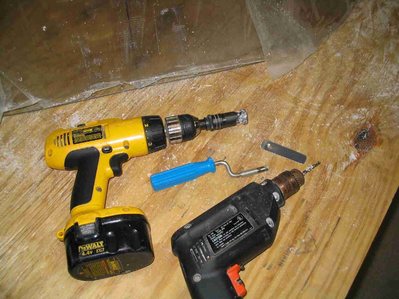
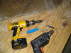 E
Spent the better of the morning countersinking and "dressing"
the edges of the aft canopy. The aft canopy was already
drilled with a 1/8" Plexiglas drill bit. The DeWalt
drill held the countersink with a number 40 CS bit. The
strip of .32 aluminum had a #6 dimple in it. I set the
CS to match the #6 dimple and checked every hole.
Immediately after CS'ing a hole I would enlarge it with a
5/16" Plexiglas drill bit and then deburr the back side with
the blue handled crank tool. This made for some very
nice holes. The rest of the day was spent wiring up the
strobe power pack, position and landing lights. Next
week we will rivet on the aft skin and bolt in the aft window. (7/30/06) E
Spent the better of the morning countersinking and "dressing"
the edges of the aft canopy. The aft canopy was already
drilled with a 1/8" Plexiglas drill bit. The DeWalt
drill held the countersink with a number 40 CS bit. The
strip of .32 aluminum had a #6 dimple in it. I set the
CS to match the #6 dimple and checked every hole.
Immediately after CS'ing a hole I would enlarge it with a
5/16" Plexiglas drill bit and then deburr the back side with
the blue handled crank tool. This made for some very
nice holes. The rest of the day was spent wiring up the
strobe power pack, position and landing lights. Next
week we will rivet on the aft skin and bolt in the aft window. (7/30/06) |
| |
|
  F
It has been a busy couple of weeks. The 774 top skin has
been riveted in place and looks great! Before that could
be done, I had to finish running the wires to the strobe power
supply under the left side of the baggage compartment floor
and then rivet all four floor panels into place. Since
I'm going use some electroluminescent strips under the roll
bar to use as a cabin / courtesy light I had to mount the
little transformers under the side flap cover plates.
Pictures to follow. (8/7/06) F
It has been a busy couple of weeks. The 774 top skin has
been riveted in place and looks great! Before that could
be done, I had to finish running the wires to the strobe power
supply under the left side of the baggage compartment floor
and then rivet all four floor panels into place. Since
I'm going use some electroluminescent strips under the roll
bar to use as a cabin / courtesy light I had to mount the
little transformers under the side flap cover plates.
Pictures to follow. (8/7/06) |
| |
|
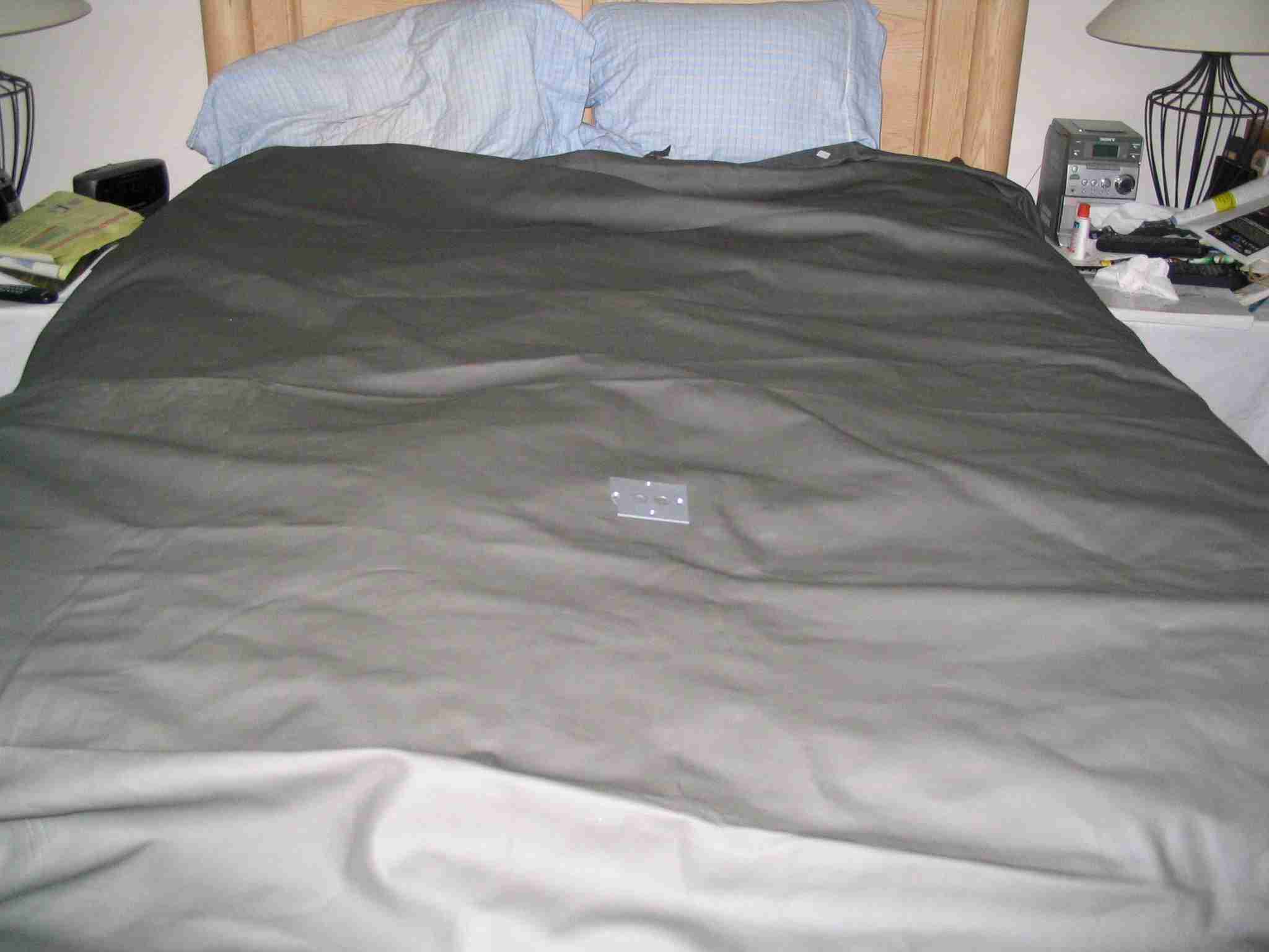
 E
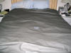
There is an outlet store in Lincolnton, NC that sells bulk
fabric and leather. I picked up three hides that exactly
match the dark gray of my panel. I had no idea the skins
are that large, this picture shows them laying on our queen
size bed. I figure only two skins will be required but
bought the third just in case I want to do the interior at
some point in the future. I have also picked up some
sheep skins that will be cut to fit over the gray leather to
keep our backsides cool during the hot summer and warm in the
cold winters. The wool will not be stitched to the
leather as I want to be able to replace them when they get
warn. (8/11/06) E
There is an outlet store in Lincolnton, NC that sells bulk
fabric and leather. I picked up three hides that exactly
match the dark gray of my panel. I had no idea the skins
are that large, this picture shows them laying on our queen
size bed. I figure only two skins will be required but
bought the third just in case I want to do the interior at
some point in the future. I have also picked up some
sheep skins that will be cut to fit over the gray leather to
keep our backsides cool during the hot summer and warm in the
cold winters. The wool will not be stitched to the
leather as I want to be able to replace them when they get
warn. (8/11/06) |
| |
|
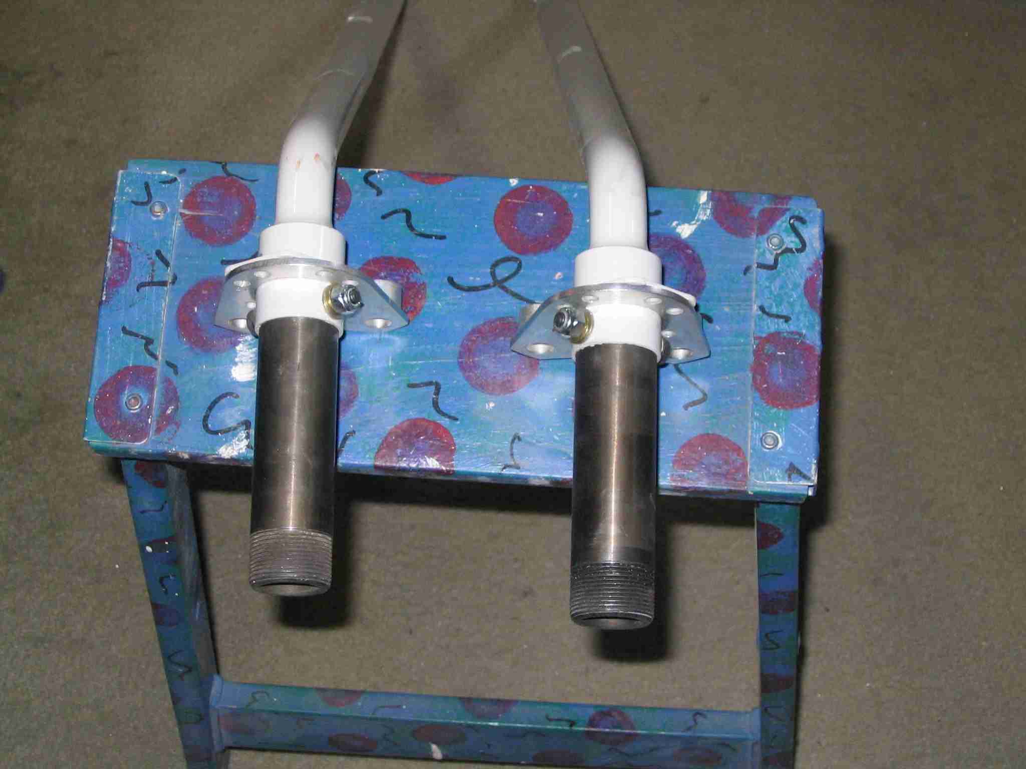
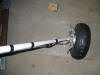
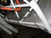
 F
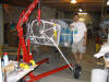
The break assembly reminds me of one of those puzzles where
you are giving a bunch of wood blocks in different shapes and
you have to arrange them in the shape of a letter, usually
"T". Here are the gear legs with the brake bracket
installed but w/o the brake and wheel pants bracket installed. (8/26/06) F
The break assembly reminds me of one of those puzzles where
you are giving a bunch of wood blocks in different shapes and
you have to arrange them in the shape of a letter, usually
"T". Here are the gear legs with the brake bracket
installed but w/o the brake and wheel pants bracket installed. (8/26/06) |
| |
|
  E
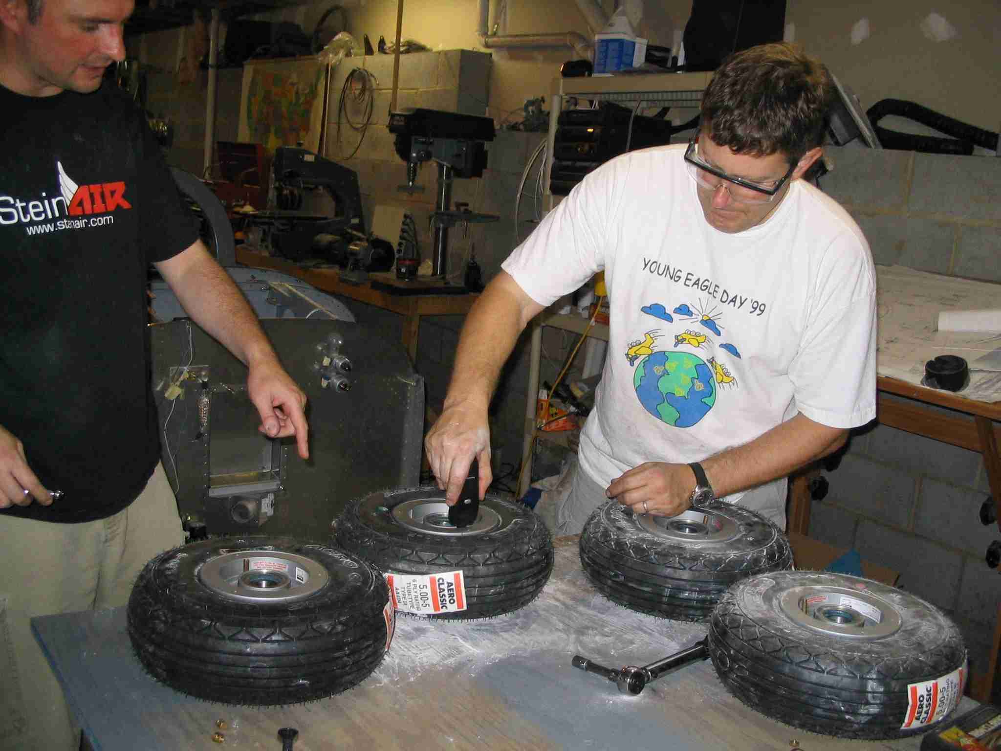
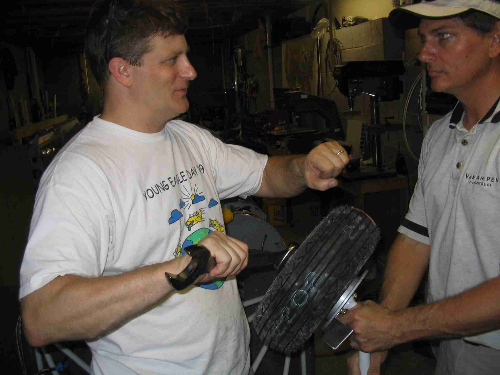
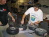
Radomir came by to help install assemble the wheels and rivet
the firewall recess in place. Notice how he brought his
wheels along as well. This worked out great until we got
to his 2nd gear leg, the shaft was just a little bit oversized
and the bearings would not fit over it. What a
disappointment . Tad also showed up to
give us a hand putting the bearings on, install the engine
mount and gear legs. (8/26/06) E
Radomir came by to help install assemble the wheels and rivet
the firewall recess in place. Notice how he brought his
wheels along as well. This worked out great until we got
to his 2nd gear leg, the shaft was just a little bit oversized
and the bearings would not fit over it. What a
disappointment . Tad also showed up to
give us a hand putting the bearings on, install the engine
mount and gear legs. (8/26/06) |
| |
|
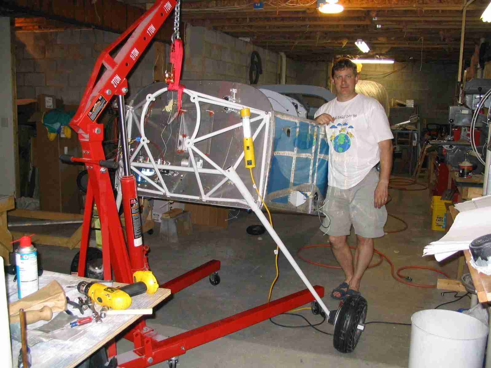
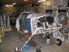
   F
Radomir had no idea how much we where going to get done when
he came over at noon. By the time we knocked off at 7:30
PM the engine mount was on, the left gear leg was bolted in
place, and the right gear leg was just about in place.
Looks like I might have to remove that right leg to inspect it
and find out why it is not sliding into place. I had no
idea the -9 tail draggers were so tall. With the engine
and wings installed, it should be a little lower. (8/27/06) F
Radomir had no idea how much we where going to get done when
he came over at noon. By the time we knocked off at 7:30
PM the engine mount was on, the left gear leg was bolted in
place, and the right gear leg was just about in place.
Looks like I might have to remove that right leg to inspect it
and find out why it is not sliding into place. I had no
idea the -9 tail draggers were so tall. With the engine
and wings installed, it should be a little lower. (8/27/06) |
| |
|
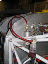
  E
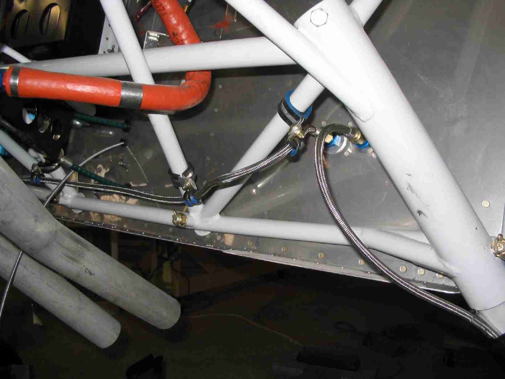
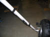
(Today, October 1, 2006, I tried to
install the throttle bracket under the engine and found that
my "great idea" of running the brake lines straight out and
across the engine mount will not work as the line interferes
with the throttle - mixture bracket. So... It
looks like I will be rerunning the right brake line.
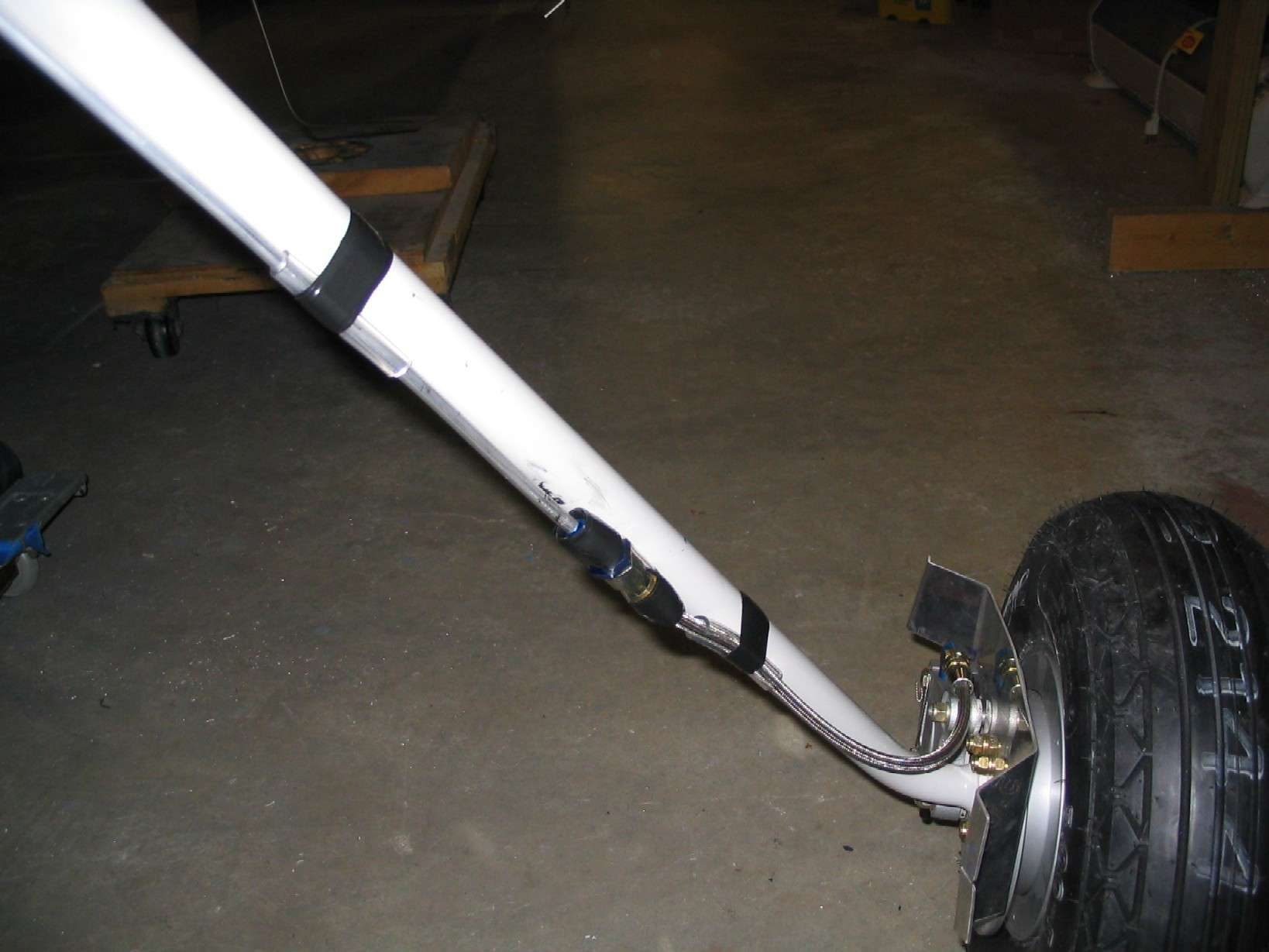
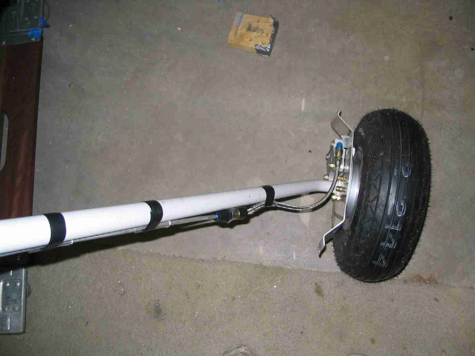
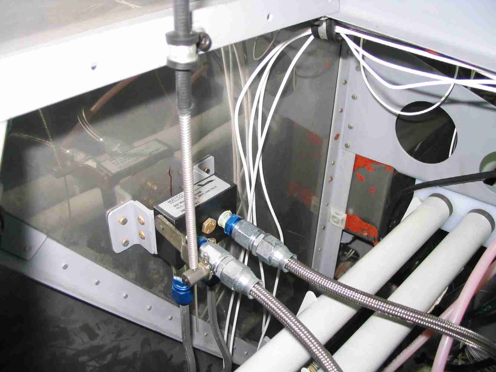
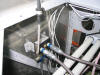
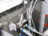
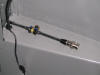
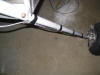
Thus do not follow my example.) Running the brake lines was easy enough. The right brake
line runs forward of the engine mount, thus keeping it away
from the exhaust and the future cowling fasteners. It
also provides a simple place to clamp it to, note the Adel
clamps waiting to be bolted together. 1/4" aluminum
tubing run down each gear leg, per the plans but in place of
making a stress loop around the brake the lines are cut short
and a 12" section of braided stainless steel Teflon brake line
run between the gear leg and brake caliper. Vinyl hose
is wrapped around the union to protect the gear leg.
(9/15/06) E
(Today, October 1, 2006, I tried to
install the throttle bracket under the engine and found that
my "great idea" of running the brake lines straight out and
across the engine mount will not work as the line interferes
with the throttle - mixture bracket. So... It
looks like I will be rerunning the right brake line.
Thus do not follow my example.) Running the brake lines was easy enough. The right brake
line runs forward of the engine mount, thus keeping it away
from the exhaust and the future cowling fasteners. It
also provides a simple place to clamp it to, note the Adel
clamps waiting to be bolted together. 1/4" aluminum
tubing run down each gear leg, per the plans but in place of
making a stress loop around the brake the lines are cut short
and a 12" section of braided stainless steel Teflon brake line
run between the gear leg and brake caliper. Vinyl hose
is wrapped around the union to protect the gear leg.
(9/15/06) |
| |
|
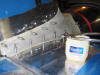
  F
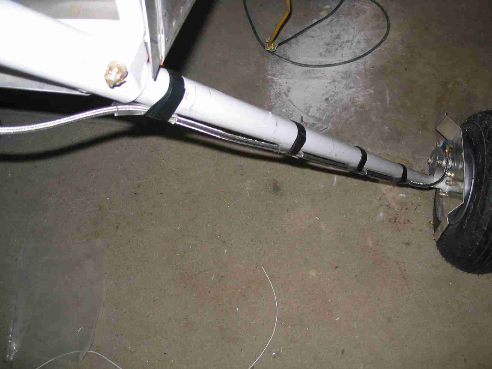
(Brake update #2: After going
through all the trouble to install these brake lines, fill the
system with fluid, etc I think this may not work either.
The union fitting looks like it might be too wide for the leg
fairing to fit over. The solution will be to use flex
line all the way down the gear leg. On the left side,
the line will run from the bulkhead fitting and on the right
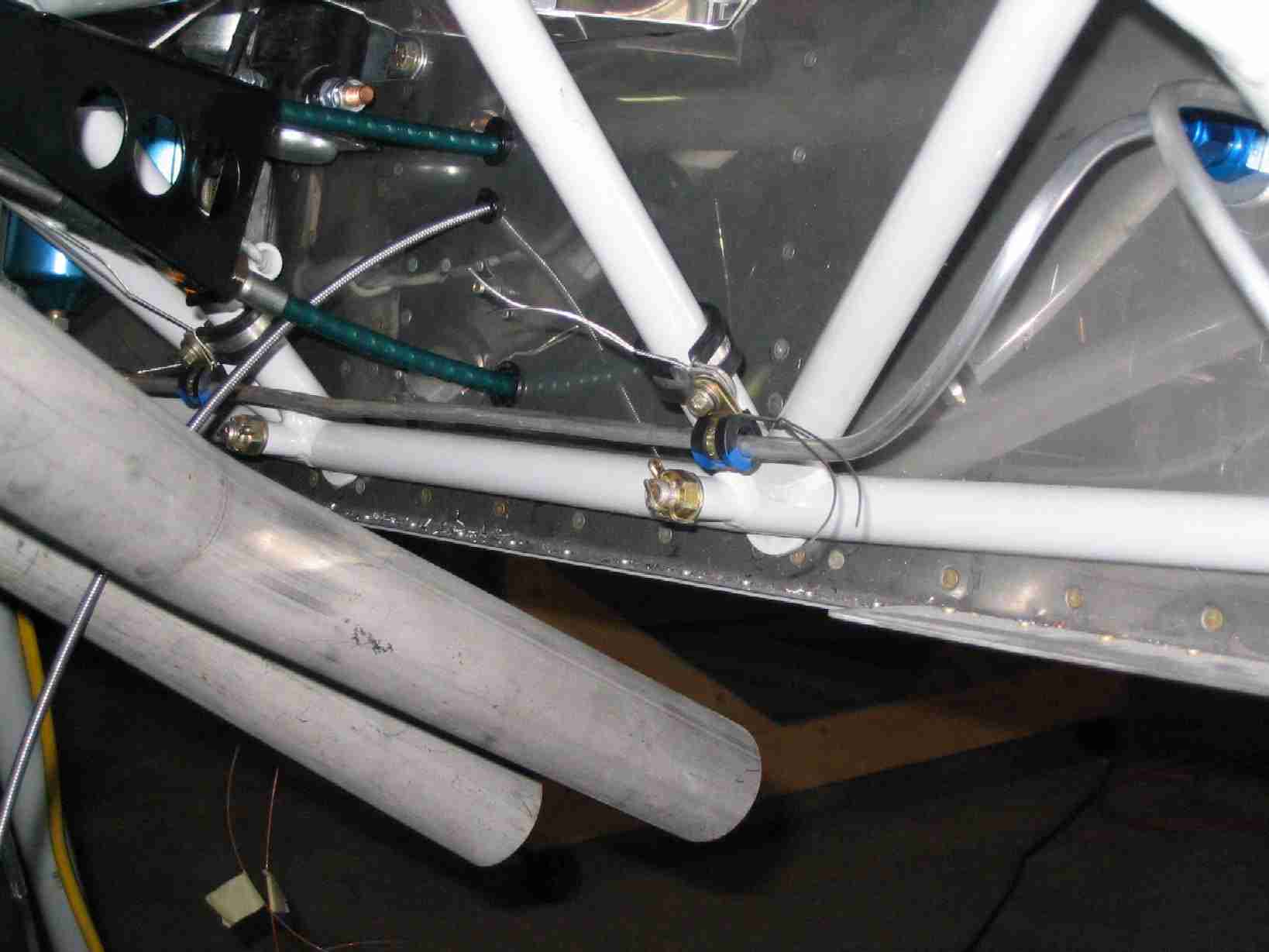
side I suspect it will run from just inside the cowling.) After installing the carburetor and the throttle-mixture
bracket I re-bent the right brake line. This wasn't a
big deal. More so since I figured out that if you use
safety wire to hold the Adel clamps closed, they are actually
very easy to install. F
(Brake update #2: After going
through all the trouble to install these brake lines, fill the
system with fluid, etc I think this may not work either.
The union fitting looks like it might be too wide for the leg
fairing to fit over. The solution will be to use flex
line all the way down the gear leg. On the left side,
the line will run from the bulkhead fitting and on the right
side I suspect it will run from just inside the cowling.) After installing the carburetor and the throttle-mixture
bracket I re-bent the right brake line. This wasn't a
big deal. More so since I figured out that if you use
safety wire to hold the Adel clamps closed, they are actually
very easy to install.
In the current issue of the RVator
they mentioned that some brake squeal can be stopped by
installing a fourth section of clear tubing and tape to the
brake line, where it runs down the gear leg. I elected
to go ahead and do this now, rather than later.
(10/14/06) |
| |
|
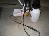 E
It was my intention to fill and test the brake system prior to
riveting the top skin on. If any leaks were discovered,
they would be easier to fix now rather than later. Today
was the day the brake lines were filled. Or, I should
say, finished getting filled. There are a lot of tricks
to doing this, like the rest of the building process, there
nothing difficult to do once you get the proper tools.
The brake lines work very similar to those on a car with the
difference being that it is best to push the fluid into the
system from the caliper rather than to let gravity and brake
pumping do the job. Also, and this is VERY important, do
not use automotive brake fluid. It is not compatible
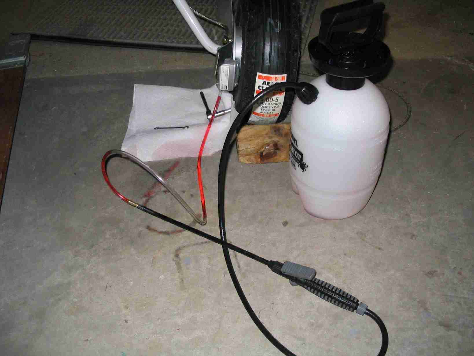
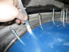
with aircraft brake systems. To push the fluid into the
system a pressurized "tool" is required. Here is my $10
chemical sprayer from the aviation section at Lowe's. I
cut the tip off the wand, inserted a 3/16" barb x 3/16" barb
splicer (Lowe's part number A-95), and then inserted a 1/4" clear
hose on the other end of the barb. Loosen the nipple on
the caliper, this is requires a 1/4" socket. Pressurize
the tank and let enough fluid out to get as many air bubbles
out of the tank's line as possible. Push the clear hose
over the nipple on the caliper.
(10/24/06) E
It was my intention to fill and test the brake system prior to
riveting the top skin on. If any leaks were discovered,
they would be easier to fix now rather than later. Today
was the day the brake lines were filled. Or, I should
say, finished getting filled. There are a lot of tricks
to doing this, like the rest of the building process, there
nothing difficult to do once you get the proper tools.
The brake lines work very similar to those on a car with the
difference being that it is best to push the fluid into the
system from the caliper rather than to let gravity and brake
pumping do the job. Also, and this is VERY important, do
not use automotive brake fluid. It is not compatible
with aircraft brake systems. To push the fluid into the
system a pressurized "tool" is required. Here is my $10
chemical sprayer from the aviation section at Lowe's. I
cut the tip off the wand, inserted a 3/16" barb x 3/16" barb
splicer (Lowe's part number A-95), and then inserted a 1/4" clear
hose on the other end of the barb. Loosen the nipple on
the caliper, this is requires a 1/4" socket. Pressurize
the tank and let enough fluid out to get as many air bubbles
out of the tank's line as possible. Push the clear hose
over the nipple on the caliper.
(10/24/06) |
| |
|
  F
Before you go to Lowe's, remove the cap from the brake
reservoir and take it with you. After selecting the
sprayer of choice, move on to the aviation plumping section
and pick up a 1/4" threaded section, a 1/4" x 1/8" tube to
female pipe coupling with insert (Lowe's part number A-15), and about
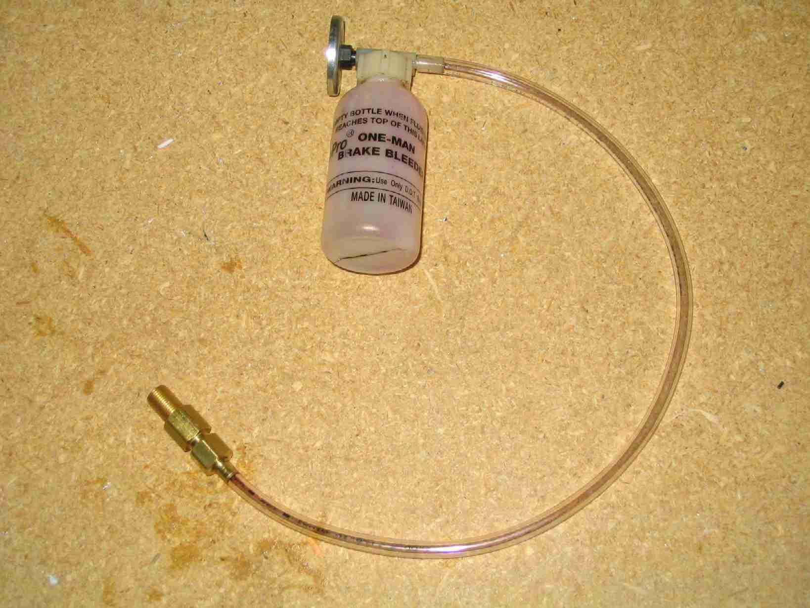
six feet of 1/8" clear vinyl hose. On the way home, stop
by an automotive parts store and pick up the self bleeder
bottle pictured above. The advantage to using this
bottle is that it has a straw that runs to the bottom so once
it has some fluid in it, you can's suck air back into the
system. Also, the bottle has a round magnet on it that
worked great for holding it to the engine mount. F
Before you go to Lowe's, remove the cap from the brake
reservoir and take it with you. After selecting the
sprayer of choice, move on to the aviation plumping section
and pick up a 1/4" threaded section, a 1/4" x 1/8" tube to
female pipe coupling with insert (Lowe's part number A-15), and about
six feet of 1/8" clear vinyl hose. On the way home, stop
by an automotive parts store and pick up the self bleeder
bottle pictured above. The advantage to using this
bottle is that it has a straw that runs to the bottom so once
it has some fluid in it, you can's suck air back into the
system. Also, the bottle has a round magnet on it that
worked great for holding it to the engine mount.
After putting it all together you are
ready to start pumping fluid into your brake system.
Two things, remember to check to make
sure all of your fittings are tight before you start pumping
fluid and tighten the nipple on the brake caliper before
trying the brakes. Please don't ask why I know these
things.
In case you were wondering, yes, I
had a leak. One of the fittings on the braided stainless
steel line that runs from the pilot's side right brake peddle
to the parking brake valve was defective. The line was
removed, the offending fitting cut off, and replaced, and the
line was reinstalled. Another reason to do this before
riveting the top skin on.
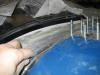
One advantage to the plastic brake
lines Van's spec's in the kit is that you can see the air
bubbles moving through the system. (10/24/06) |
| |
|
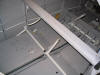
   E
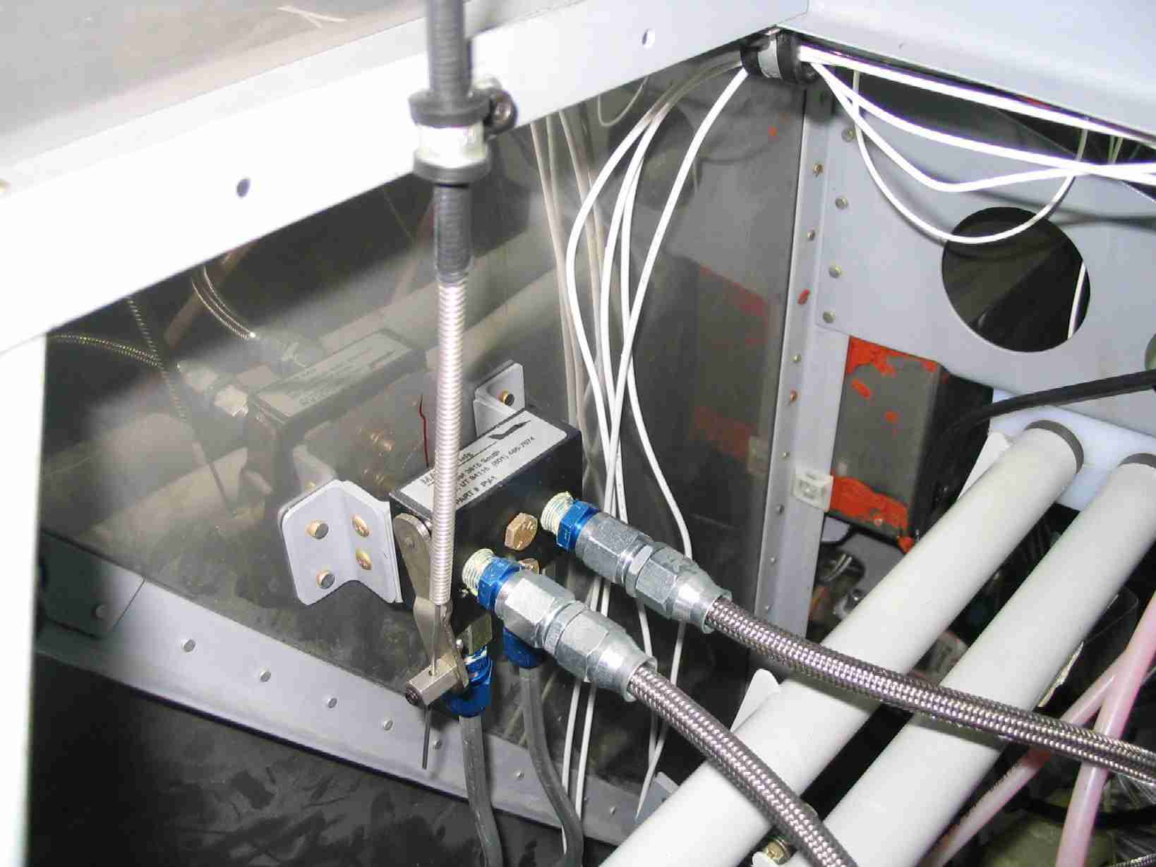
Ah, the joys of home building. When the parking brake
valve was first installed, it was my understanding that the
valve would be open (parking brake off) if the lever was
vertical, either up or down, based on the orientation in my
installation, and the valve would be closed (parking brake on)
when the lever is horizontal. After filling the brake
lines, I found this was not the case. E
Ah, the joys of home building. When the parking brake
valve was first installed, it was my understanding that the
valve would be open (parking brake off) if the lever was
vertical, either up or down, based on the orientation in my
installation, and the valve would be closed (parking brake on)
when the lever is horizontal. After filling the brake
lines, I found this was not the case.
The first picture is how the parking
brake cable was originally installed. This was supposed
to be "Off" and the middle picture was the position when the
brakes are set or "On". This is wrong. The middle
picture in fact is where the valve needs to be in the "Off"
position and the photo on the right is the valve in the set or
"On" position.
It was easy enough to make this
change now, before the top skin is riveted in place.
(10/24/06) |
| |
|
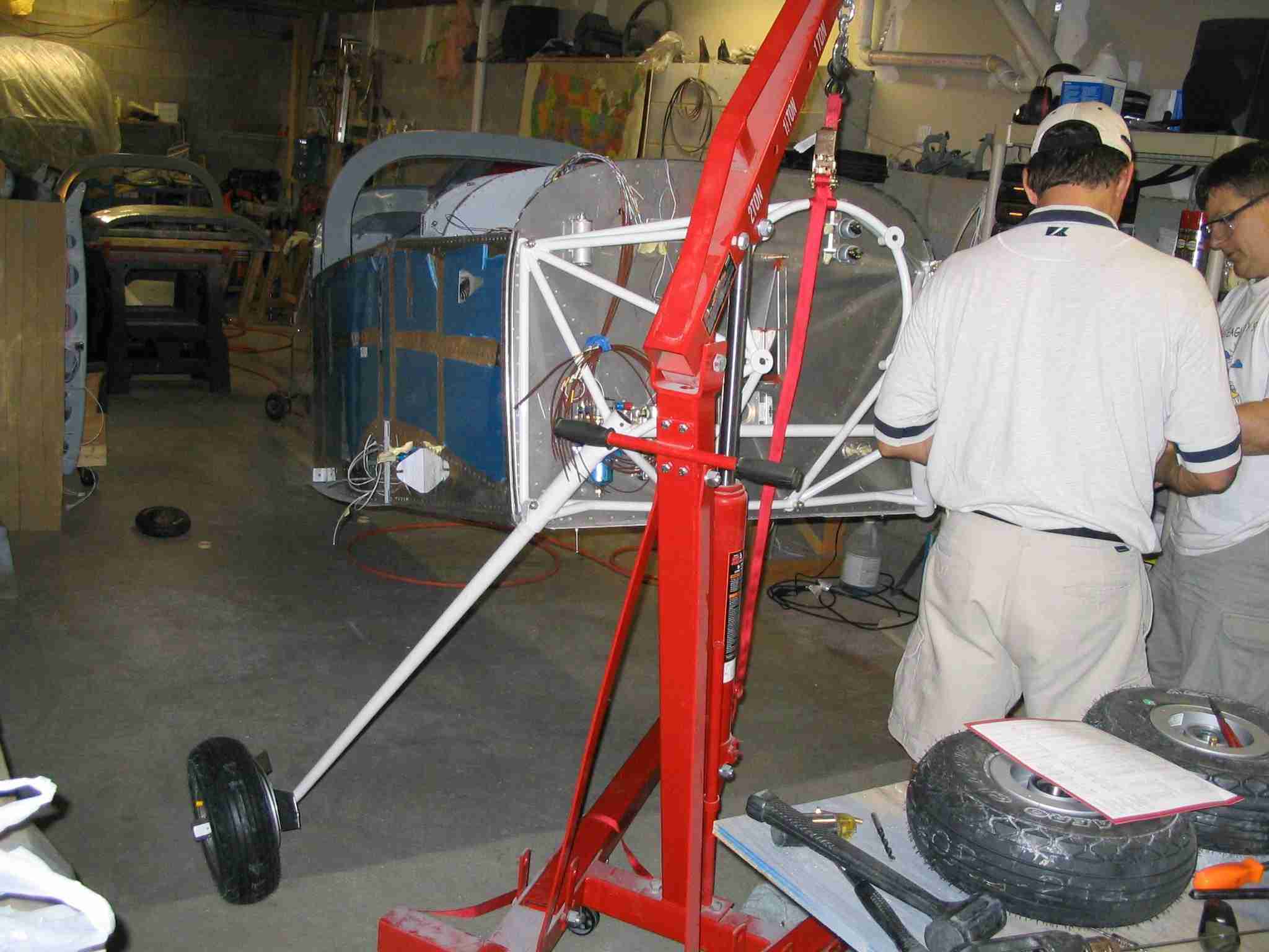
 F
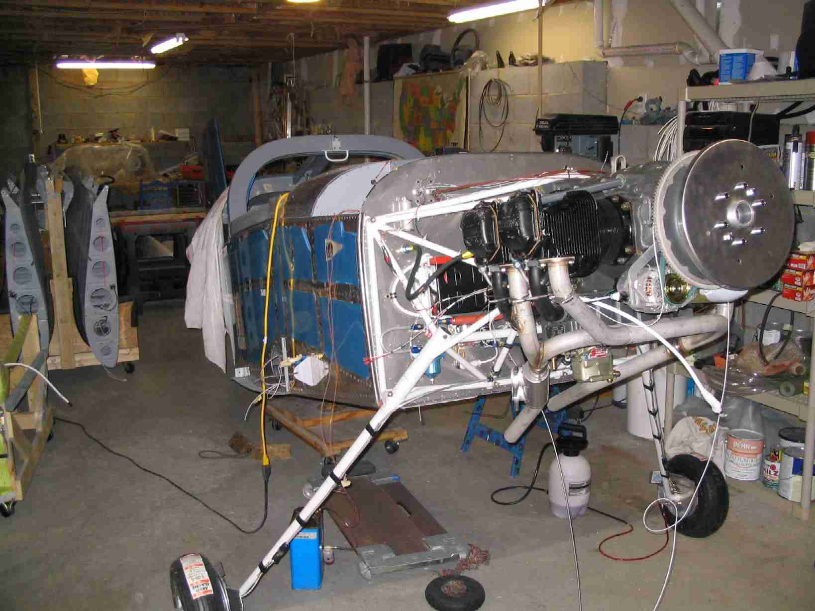
My wife pointed out I had not yet posted a picture of the
plane with the engine and gear on. (11/2/06) F
My wife pointed out I had not yet posted a picture of the
plane with the engine and gear on. (11/2/06) |
| |
|
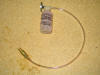
 E
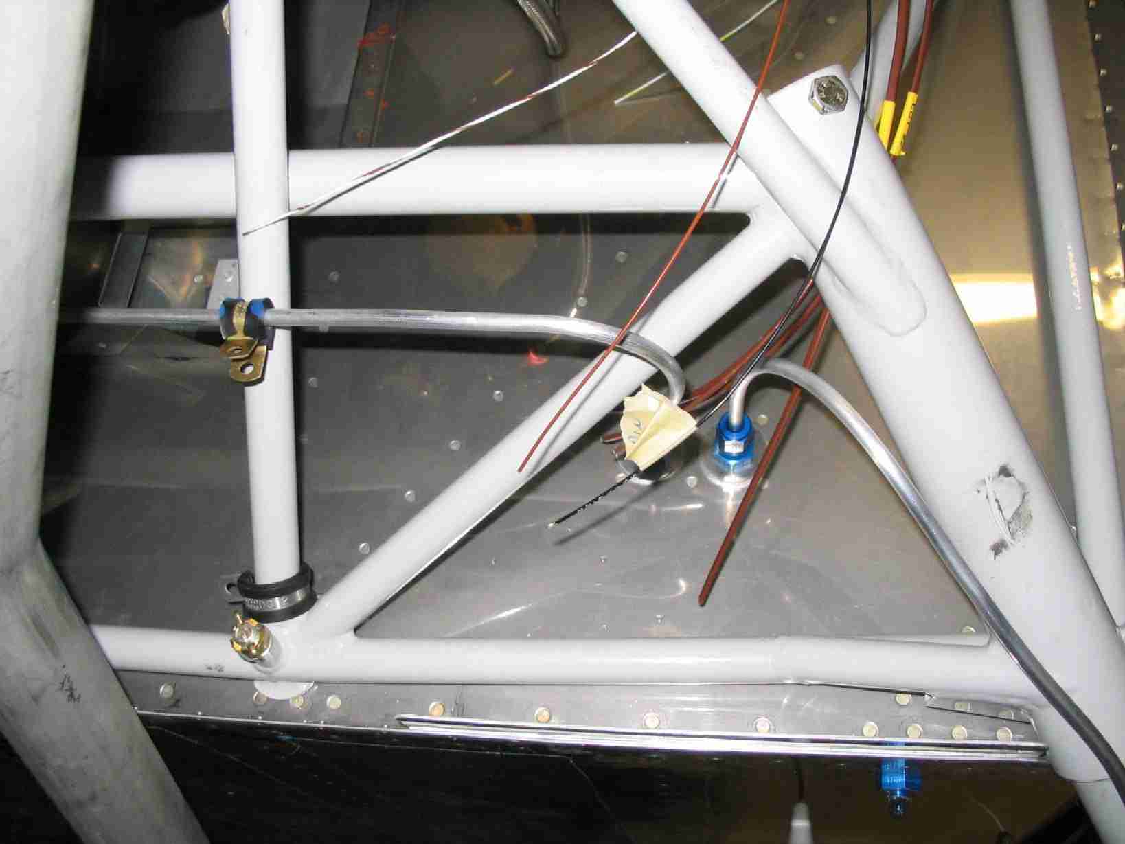
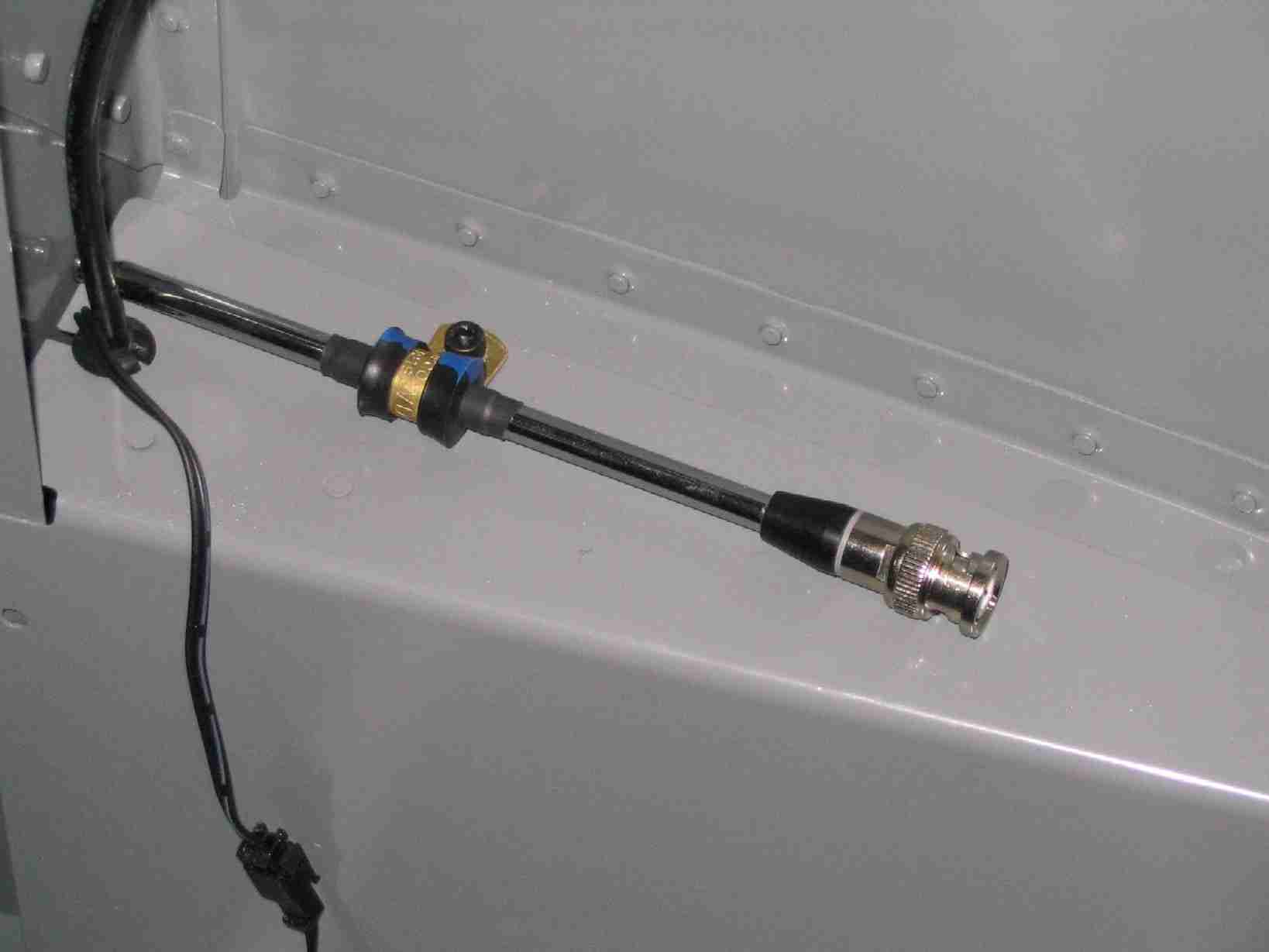
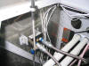
The ELT tray had a loop to hold the emergency antenna but when
I mounted the tray in the floor I had to cut it off.
When I did this I wasn't sure where to mount the antenna until
the other day. I used some shrink tubing around the
antenna to keep it from sliding out of the adel clamp and the
screw holding the clamp in place is used to keep the right
flap lever cover in place. (11/2/06) E
The ELT tray had a loop to hold the emergency antenna but when
I mounted the tray in the floor I had to cut it off.
When I did this I wasn't sure where to mount the antenna until
the other day. I used some shrink tubing around the
antenna to keep it from sliding out of the adel clamp and the
screw holding the clamp in place is used to keep the right
flap lever cover in place. (11/2/06) |
| |
|
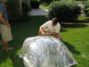
 F
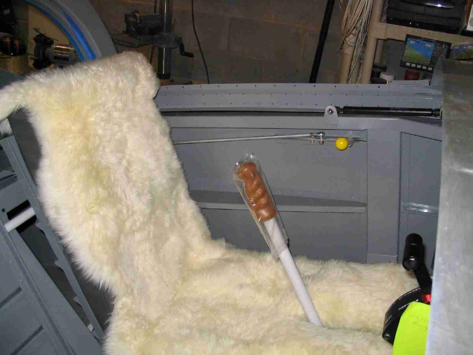
Last week was a great week here at Bill's Aircraft Factory!
On Thursday I picked up my seats from the upholsterer.
Mr. Leon Brown did an outstanding job and I can highly
recommend him. He isn't cheep but I don't mind paying
for quality. All the cushions and boot covers are in
dark gray and he made some sheepskin slip covers for the
seats. It may look a little bling, as the kids would
say, but they will be cool in the summer and warm in the
winter. The best part is they can be easily replaced
should they get trashed as they are held in place by elastic
straps. (11/2/06) F
Last week was a great week here at Bill's Aircraft Factory!
On Thursday I picked up my seats from the upholsterer.
Mr. Leon Brown did an outstanding job and I can highly
recommend him. He isn't cheep but I don't mind paying
for quality. All the cushions and boot covers are in
dark gray and he made some sheepskin slip covers for the
seats. It may look a little bling, as the kids would
say, but they will be cool in the summer and warm in the
winter. The best part is they can be easily replaced
should they get trashed as they are held in place by elastic
straps. (11/2/06) |
| |
|
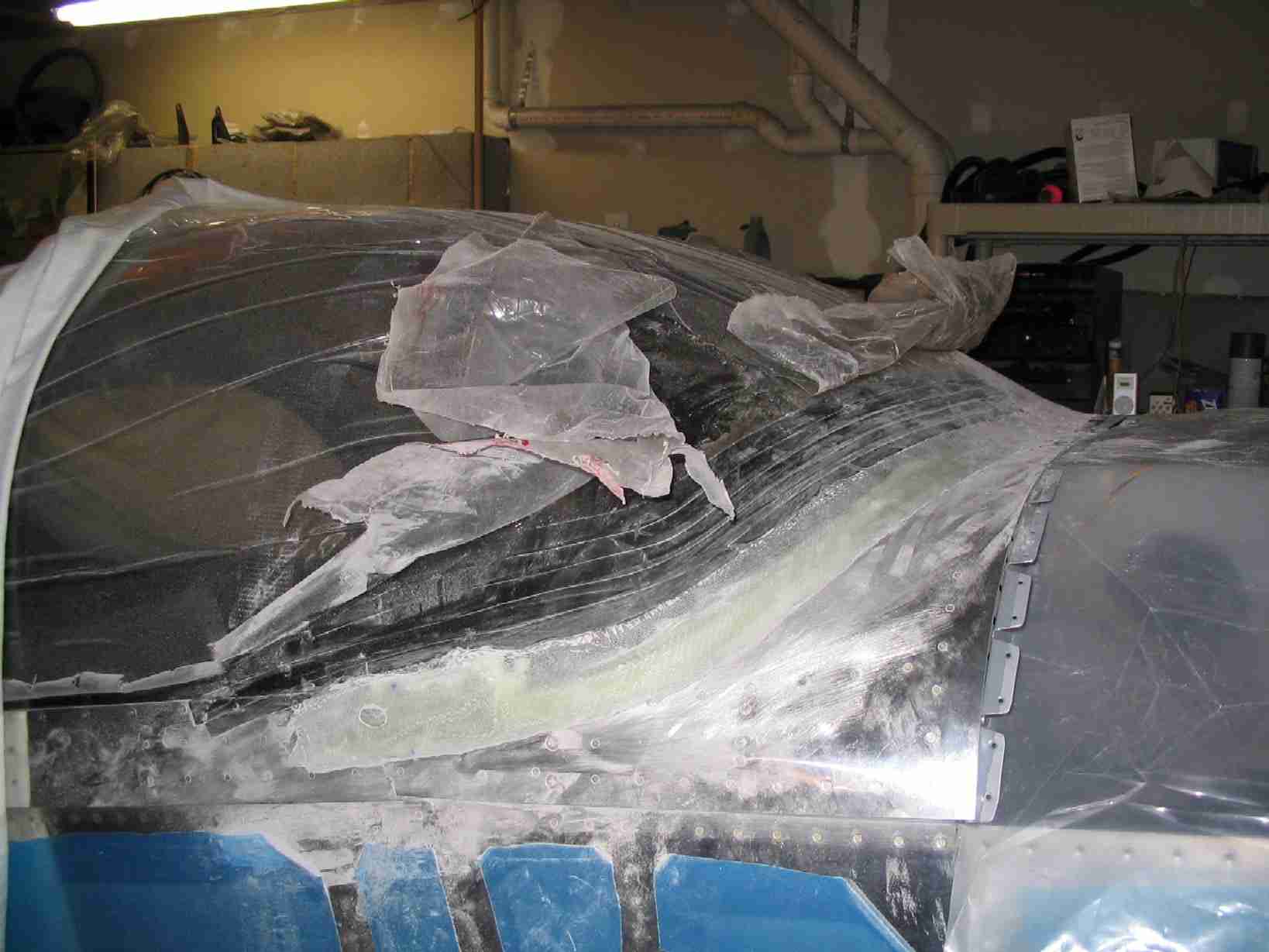
 E
Fiber glassing in the canopy wasn't that big of a deal.
Unfortunately, I didn't take any picture of the process
because my hands were a bit messy. The instructions in the
manual worked great. and after a short working session,
it was time to walk away and let it harden. The only way
I strayed from the instructions was in using some tooling
dough (epoxy and micro balloons) to fill the gap between
the canopy and top skin. After that, I laid
progressively wider strips of cloth, starting at 1/2" and
finishing with 2" strips. Each layer of strips was 1/4"
wider than the previous. The strips were laid with the
ends butting up against one another and the butt joints were
offset from one another. The first being in the center,
the second on the right side, the third on the left, then back
to the center, right, left, etc. until all the cloth was used
up. That is a hint, cut all your cloth before you start
and lay it out in the order in which it will be used. (12/3/06) E
Fiber glassing in the canopy wasn't that big of a deal.
Unfortunately, I didn't take any picture of the process
because my hands were a bit messy. The instructions in the
manual worked great. and after a short working session,
it was time to walk away and let it harden. The only way
I strayed from the instructions was in using some tooling
dough (epoxy and micro balloons) to fill the gap between
the canopy and top skin. After that, I laid
progressively wider strips of cloth, starting at 1/2" and
finishing with 2" strips. Each layer of strips was 1/4"
wider than the previous. The strips were laid with the
ends butting up against one another and the butt joints were
offset from one another. The first being in the center,
the second on the right side, the third on the left, then back
to the center, right, left, etc. until all the cloth was used
up. That is a hint, cut all your cloth before you start
and lay it out in the order in which it will be used. (12/3/06) |
| |
|
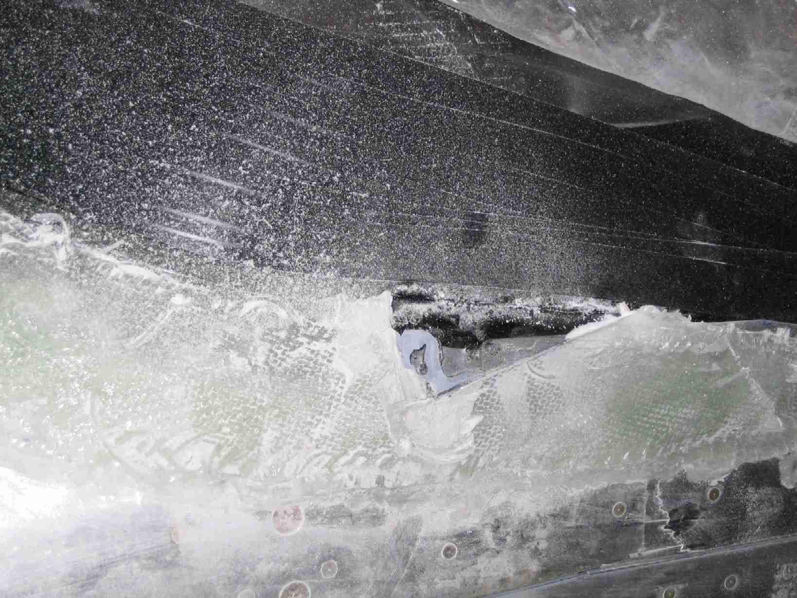
 F
After the fiber glass hardened I realized that the tabs where
the Plexiglas passed through the skin did not look very good.
The aluminum tabs were sticking out and it looked like my plane had
ears. Very carefully the tabs were cut off with a Dremel
and using bidirectional cloth I found at a hobby shop the
holes were covered and filled. Once it was completed,
you could not tell I performed minor surgery on this area. (12/8/06) F
After the fiber glass hardened I realized that the tabs where
the Plexiglas passed through the skin did not look very good.
The aluminum tabs were sticking out and it looked like my plane had
ears. Very carefully the tabs were cut off with a Dremel
and using bidirectional cloth I found at a hobby shop the
holes were covered and filled. Once it was completed,
you could not tell I performed minor surgery on this area. (12/8/06) |
| |
|
  E
(Brake update #3: Sure enough, the union fitting on the
brake line was too wide for the gear leg fairings.)
Finally the brake lines are in to stay! I special
ordered stainless steel brake lines to run from the firewall
penetration and down the gear legs. The right side line
took some extra supports but not a big deal. Now I'm
ready to fit the cowling. (12/10/06) E
(Brake update #3: Sure enough, the union fitting on the
brake line was too wide for the gear leg fairings.)
Finally the brake lines are in to stay! I special
ordered stainless steel brake lines to run from the firewall
penetration and down the gear legs. The right side line
took some extra supports but not a big deal. Now I'm
ready to fit the cowling. (12/10/06) |
| |
|
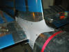
   F
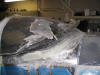
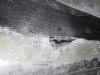
What can I say? I do make some mistakes when building
but as someone once said, it is not the mistakes you make but
how you fix them that counts. Extreme caution was used
to fit the tip-up canopy to my fuselage and it fit perfect
right up until I riveted it together. Apparently after
the tip-up frame was riveted together, I never clecoed on the
top forward skin to see if it still lined up. After
friber glassing the canopy on I was ready to begin fitting the
cowling, which required putting that skin in place. That
was when I noticed the left and right sides lifted up and out.
The first picture shows the gap on the right side. The
left side was even larger. The middle picture shows the
shims I made to go under the skin at the rivet line. The
third picture shows the skin after the shims are clecoed in
place. I suspect this will pull down some once they are
riveted in place. If this happens, I will build up that
skin some fiber glass and tooling dough. Not a big deal
and easy enough to fix. (12/30/06) F
What can I say? I do make some mistakes when building
but as someone once said, it is not the mistakes you make but
how you fix them that counts. Extreme caution was used
to fit the tip-up canopy to my fuselage and it fit perfect
right up until I riveted it together. Apparently after
the tip-up frame was riveted together, I never clecoed on the
top forward skin to see if it still lined up. After
friber glassing the canopy on I was ready to begin fitting the
cowling, which required putting that skin in place. That
was when I noticed the left and right sides lifted up and out.
The first picture shows the gap on the right side. The
left side was even larger. The middle picture shows the
shims I made to go under the skin at the rivet line. The
third picture shows the skin after the shims are clecoed in
place. I suspect this will pull down some once they are
riveted in place. If this happens, I will build up that
skin some fiber glass and tooling dough. Not a big deal
and easy enough to fix. (12/30/06) |
| |
|
E
Page
F |