|
Still struggling with
cooling the engine but the good news is, the end looks like it might be in
sight. I'm making
these changes one at a time. Otherwise I will never know what had
the most impact.
After the change above, I did see a difference in my CHT's but not enough
to make a difference. When I started this quest to balance my CHT's
I was seeing the following temps in cruise:
#1: 363
#2: 358
#3: 408
#4: 364
After working on the top cowing I played
around with adding air dams made of aluminum tape to the front of
cylinders #1 and #2. This worked to balance out cylinders 1, 2, & 4
but #3 was still running about 45 degrees higher than the other three.
Next up was to dded a second washer
behind the #3 cylinder. From the time I first installed the baffles,
there was one washer there and I had heard that adding a 2nd one could
only help. This change did help some and the temps on 1, 2, & 4 came
down to within 2 degrees of one another; however, #3 was still higher by
around 35 degrees. (Every change seemed to reduce the temps by five
degrees, I can only hope I don't run out of ideas before getting the
temperature of that cylinder down where I want it.)
Better but not good enough. The
next trick was to make a new corner piece out of airseal fabric and rivet
it in the corner of cylinder #3. That was an easy change, other than
having to order more of those big headed rivets from Van's.
Subsequent test flights didn't indicate any noticeable change in the CHT's.
I suppose the original corner seal was fine.
Somewhere in here I thought maybe I was
having an intake leak, so I changed out the intake gasket and rubber tube
down at the sump. No change, other than spending a few dollars with
Aircraft Spruce for the parts.
The next test was to find out if my CHT
probe was any good. This was simple enough, just a simple swap of
the #1 and #3 probes and go fly. No joy. :(
 E
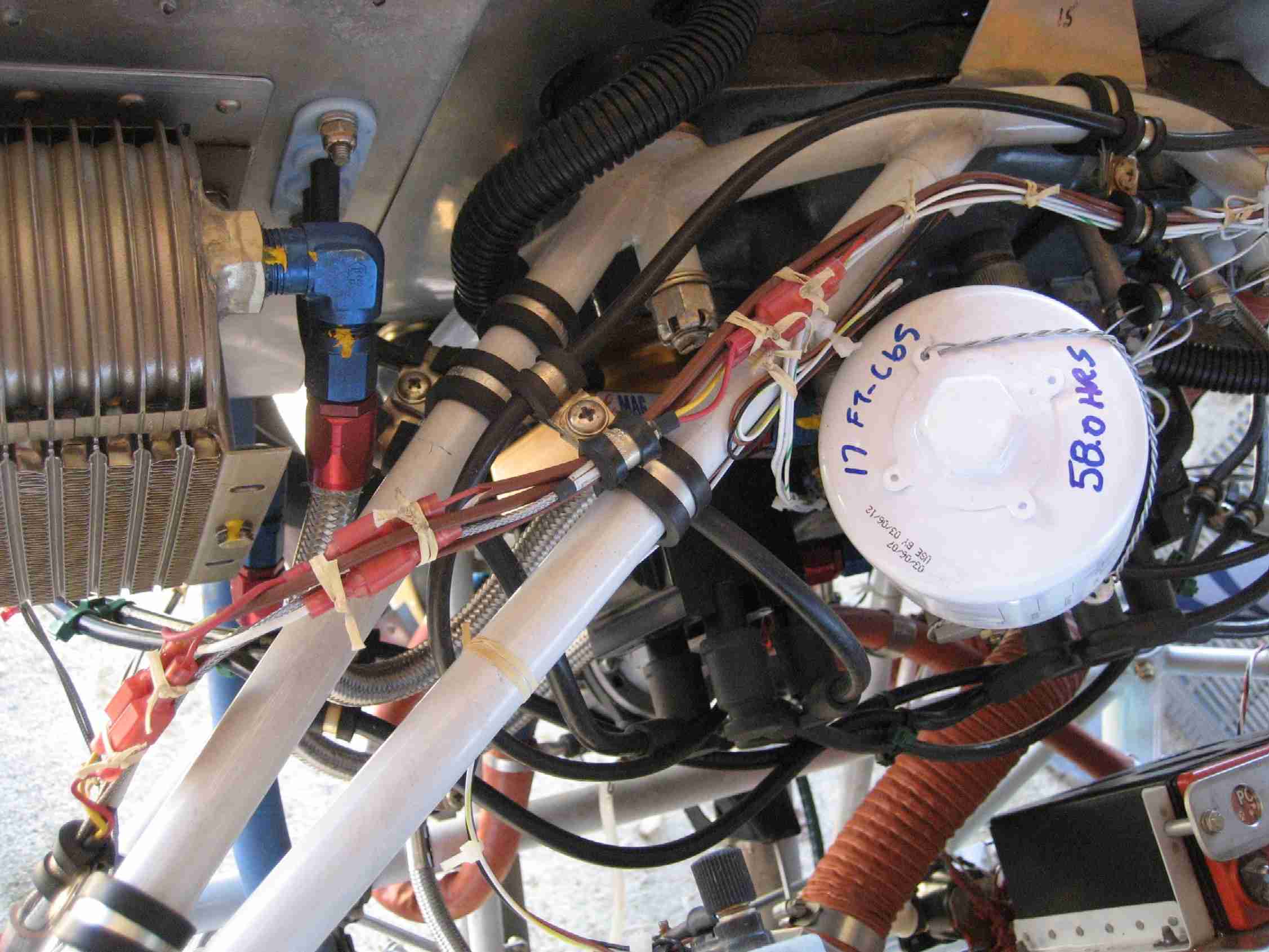
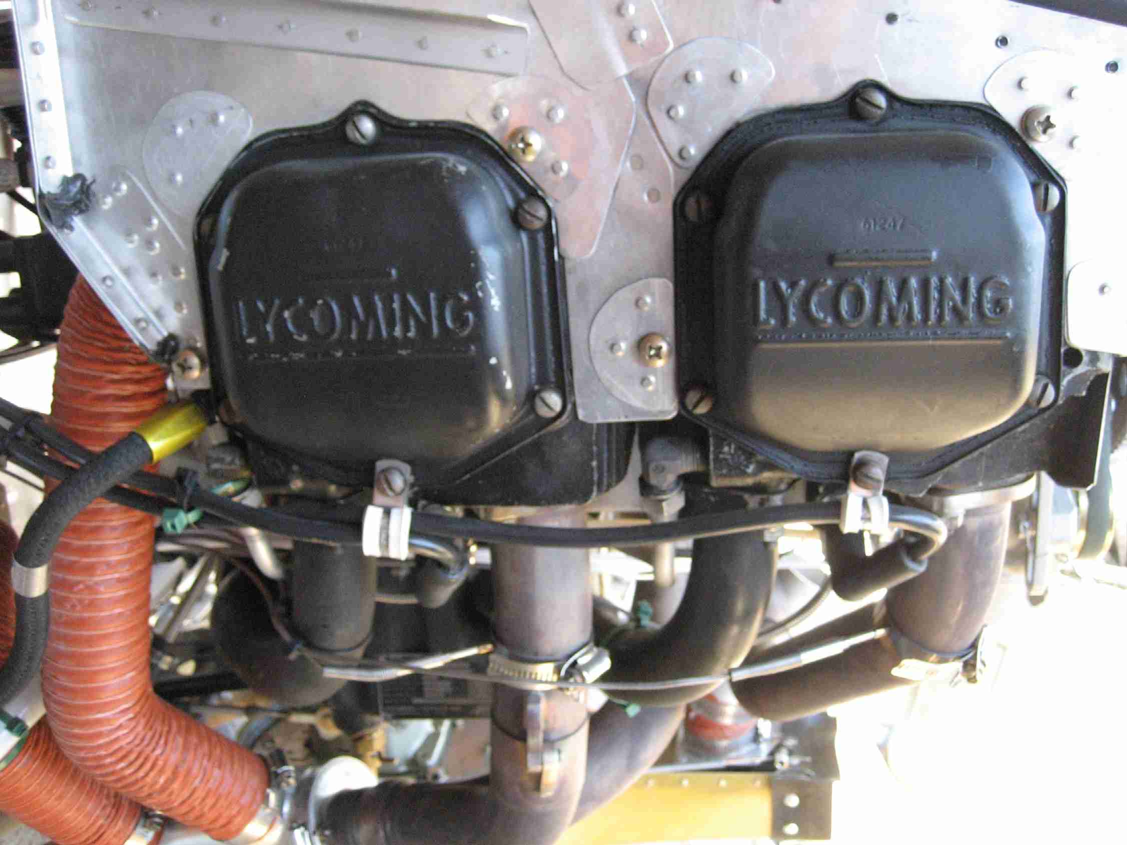
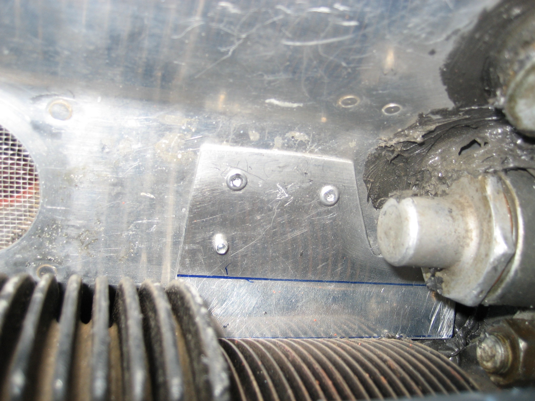
What next? After looking over the engine a friend commented that the
O-320 baffles didn't wrap up tight against the cylinder base of #3.
Sure enough, after getting up on a chair and taking a closer look myself,
you could see there was a one inch gap where the baffle did not wrap
tightly against the cylinder base. I emphasize "base" because the
baffles fit the head just fine. That must be where one of the major
difference in the O-290 vs. O-320 cylinders is. I quickly fabricated
a small piece of aluminum to fill that hole, pop-riveted it in place, and
RTV'ed every gap I could find anywhere on the engine. Two subsequent
test flights found my CHT"S running: E
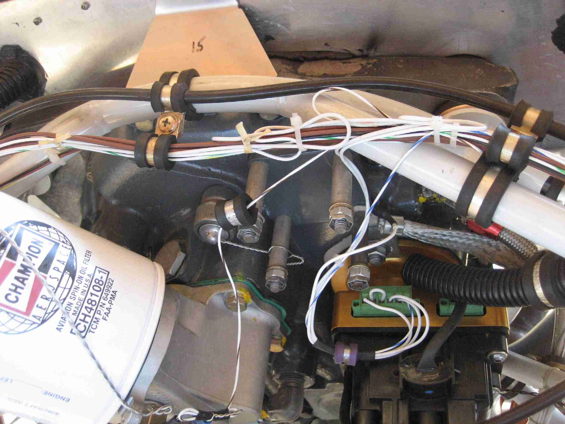
What next? After looking over the engine a friend commented that the
O-320 baffles didn't wrap up tight against the cylinder base of #3.
Sure enough, after getting up on a chair and taking a closer look myself,
you could see there was a one inch gap where the baffle did not wrap
tightly against the cylinder base. I emphasize "base" because the
baffles fit the head just fine. That must be where one of the major
difference in the O-290 vs. O-320 cylinders is. I quickly fabricated
a small piece of aluminum to fill that hole, pop-riveted it in place, and
RTV'ed every gap I could find anywhere on the engine. Two subsequent
test flights found my CHT"S running:
#1: 339
#2: 341
#3: 365
#4: 339
Get this, those temps were with OAT's of
70 and when the temps above were recorded, the OAT's were in the 40's and
50's so I'm definitely making progress but I still have that one outlier.
Unfortunately I didn't take a picture while running at cruise power on
this test day and don't want to post erroneous numbers. The good
thing is that the CHT"s for 1, 2, & 4 where within two degrees of each
other and #3 was the same 20 to 25 degrees out and better yet, it was
below 400. Progress has most definitely been made!
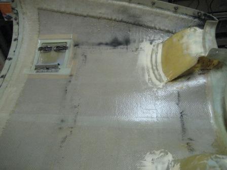
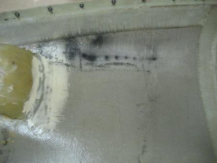
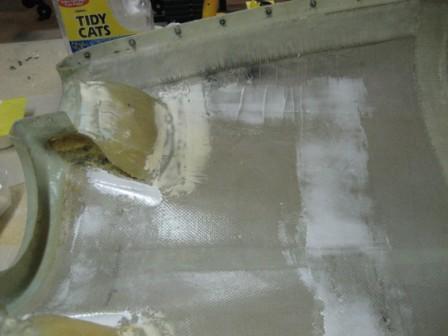
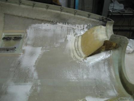
 F
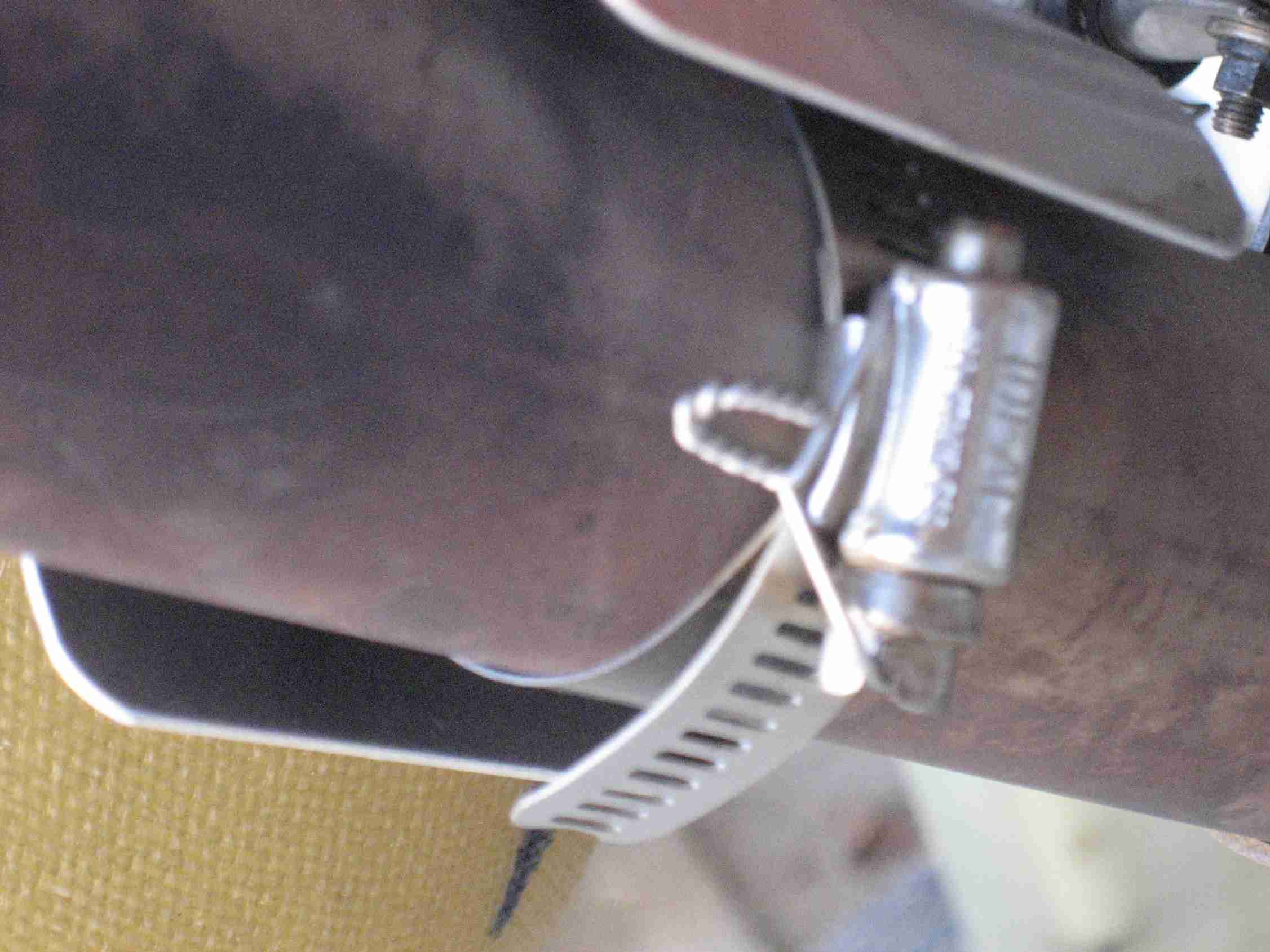
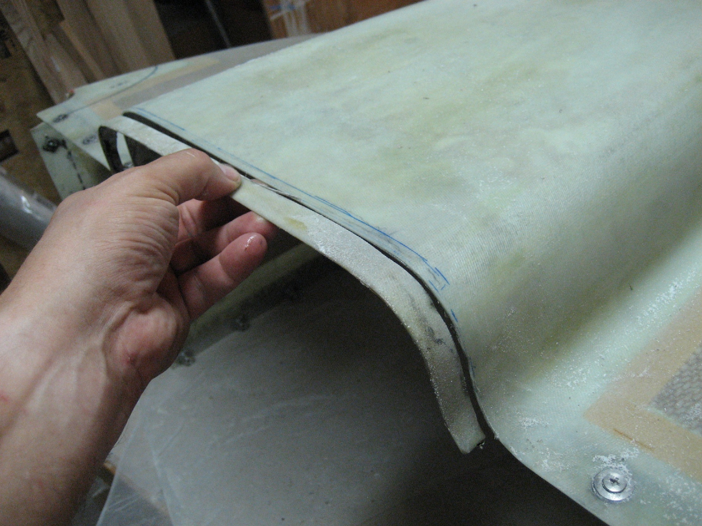
The last change I wanted to make was to trim the air outlet back a little
bit. Remember, I live in the Southeast and from June to September,
OAT's in the mid 90's is common. When I fit my cowl, I realized
there would be a little tail of the air outlet tunnel that would stick
back behind the firewall. Thinking this would look cool, I left it
in place. In researching my cooling issues, I found that it may look
cool but this "tail" doesn't help cool the engine. About five
minutes with a body saw and belt sander and the air outlet on the lower
cowling was even with the rest of the cowling. F
The last change I wanted to make was to trim the air outlet back a little
bit. Remember, I live in the Southeast and from June to September,
OAT's in the mid 90's is common. When I fit my cowl, I realized
there would be a little tail of the air outlet tunnel that would stick
back behind the firewall. Thinking this would look cool, I left it
in place. In researching my cooling issues, I found that it may look
cool but this "tail" doesn't help cool the engine. About five
minutes with a body saw and belt sander and the air outlet on the lower
cowling was even with the rest of the cowling.
Stand by for the results of more test
flights. (This sure makes me happy that the plane isn't painted
yet!)
(7/2/08) |