| |
|
 F
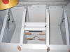
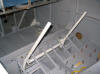
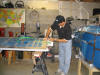
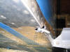
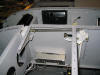
This is the right side crotch strap anchor. Although the
-9 is not aerobatic I strongly believe in the use of crotch
straps when utilizing a mutipoint harness, such as will be
installed in this plane. The crotch or anti-submarine
strap prevents the lap belt from riding up above your hip
bones in an accident and damaging your internal organs.
(8/30/05) F
This is the right side crotch strap anchor. Although the
-9 is not aerobatic I strongly believe in the use of crotch
straps when utilizing a mutipoint harness, such as will be
installed in this plane. The crotch or anti-submarine
strap prevents the lap belt from riding up above your hip
bones in an accident and damaging your internal organs.
(8/30/05) |
| |
|
  E
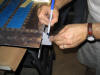
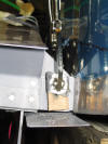
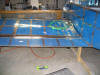
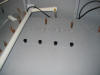
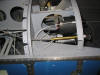
When fitting the heater cover you have to drill four holes
through the aluminum angles on the floor. This would
have been much easier to do had the instructions mentioned it
before now but they didn't so I had to figure out how to
measure and mark them. I started by marking the correct
lateral location on the heater cover. Then I took a small piece
of AA and measured down to the appropriate depth and drilled a
#30 hole in the side. (Ok two holes but only the lower
hole was used to drill the AA on the floor.) I then
taped the AA in the correct location, held it in place, and
drilled the hole. After all four holes were drilled with
the #30 bit I enlarged them with a #11 bit. Without the
angle drive I don't think it is possible to drill these holes.
Upon removing the heater cover the holes were perfectly
centered on the web.
(8/31/05) E
When fitting the heater cover you have to drill four holes
through the aluminum angles on the floor. This would
have been much easier to do had the instructions mentioned it
before now but they didn't so I had to figure out how to
measure and mark them. I started by marking the correct
lateral location on the heater cover. Then I took a small piece
of AA and measured down to the appropriate depth and drilled a
#30 hole in the side. (Ok two holes but only the lower
hole was used to drill the AA on the floor.) I then
taped the AA in the correct location, held it in place, and
drilled the hole. After all four holes were drilled with
the #30 bit I enlarged them with a #11 bit. Without the
angle drive I don't think it is possible to drill these holes.
Upon removing the heater cover the holes were perfectly
centered on the web.
(8/31/05) |
| |
|
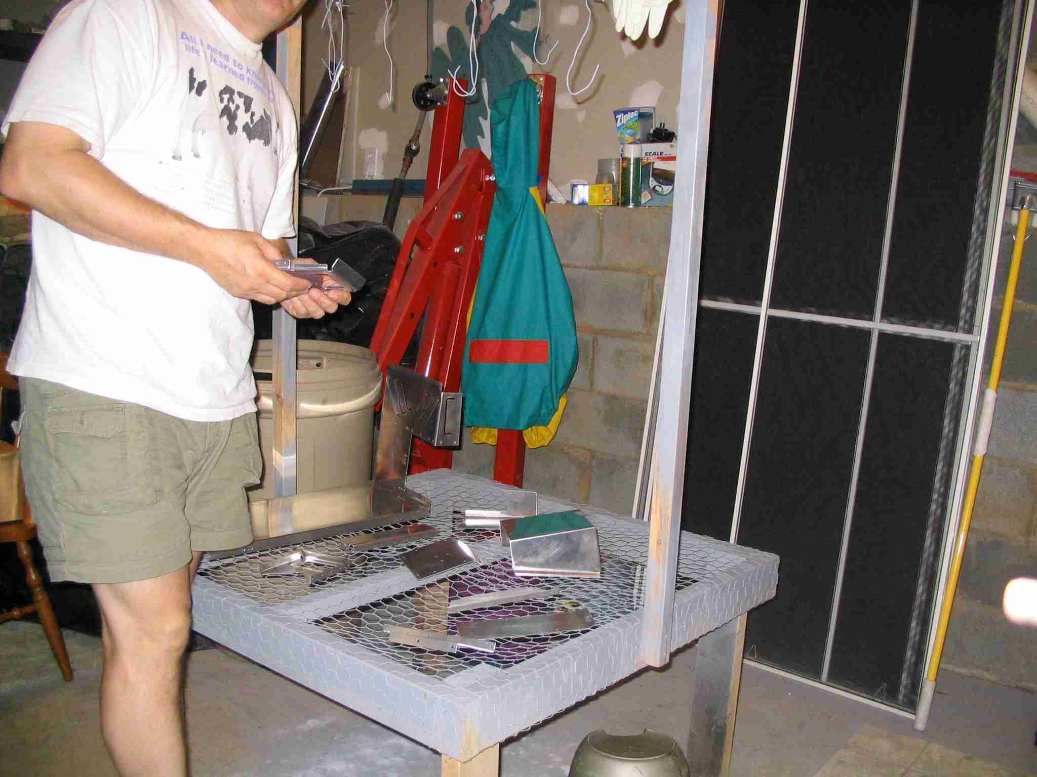
 F
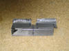
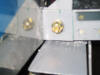
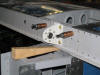
There sure are a lot of small parts that go in the forward
fuselage floor section. Here is just a small sample of
some of them ready for painting.
(9/4/05) F
There sure are a lot of small parts that go in the forward
fuselage floor section. Here is just a small sample of
some of them ready for painting.
(9/4/05) |
| |
|
 E
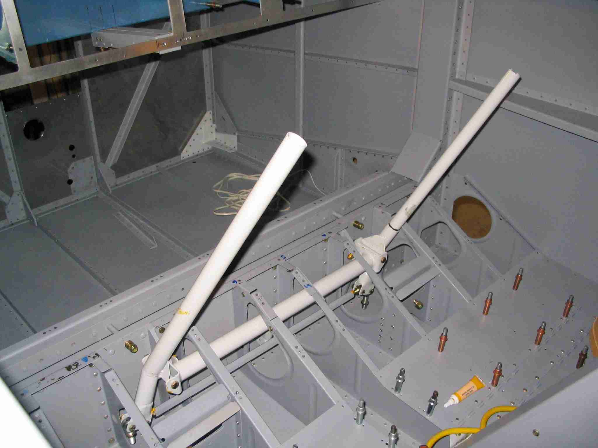
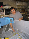
The control sticks are installed. Next up is the wing
installation. (9/16/05) E
The control sticks are installed. Next up is the wing
installation. (9/16/05) |
| |
|
 F
Match drilled the horizontal stabilizer to the fuselage.
This was a straightforward processes. Checkout the tip
on my the Things to Consider
page regarding how to accurately measure the HS and wings. (9/25/05) F
Match drilled the horizontal stabilizer to the fuselage.
This was a straightforward processes. Checkout the tip
on my the Things to Consider
page regarding how to accurately measure the HS and wings. (9/25/05) |
| |
|
 E
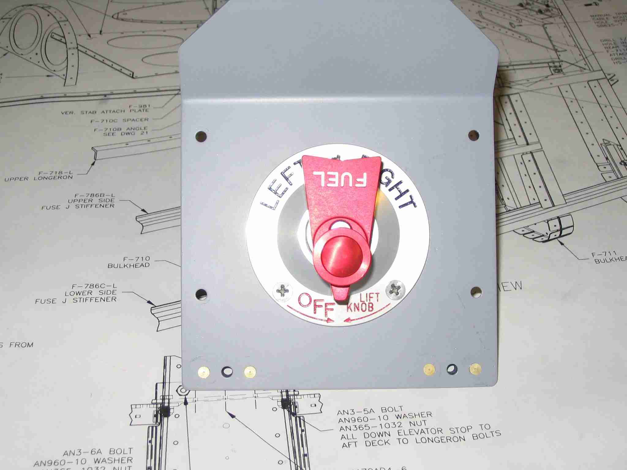
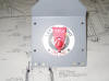
Here is the Andair fuel valve fitted to the cover plate.
This is one quality valve that every builder should consider. (9/25/05) E
Here is the Andair fuel valve fitted to the cover plate.
This is one quality valve that every builder should consider. (9/25/05) |
| |
|
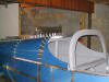
  F
Installed both wings for the first time. After
installing the right wing we noticed there was a slight
interference with aft spar bracket and the wing. After
looking at the RV-9 plans (I'm thinking the -7 does not have
this issue.) we noticed that the aft spar bracket should have
had a slight angle filed in the end to allow for the
significant dihedral in the -9's wing. (10/2/05) F
Installed both wings for the first time. After
installing the right wing we noticed there was a slight
interference with aft spar bracket and the wing. After
looking at the RV-9 plans (I'm thinking the -7 does not have
this issue.) we noticed that the aft spar bracket should have
had a slight angle filed in the end to allow for the
significant dihedral in the -9's wing. (10/2/05) |
| |
|
 E
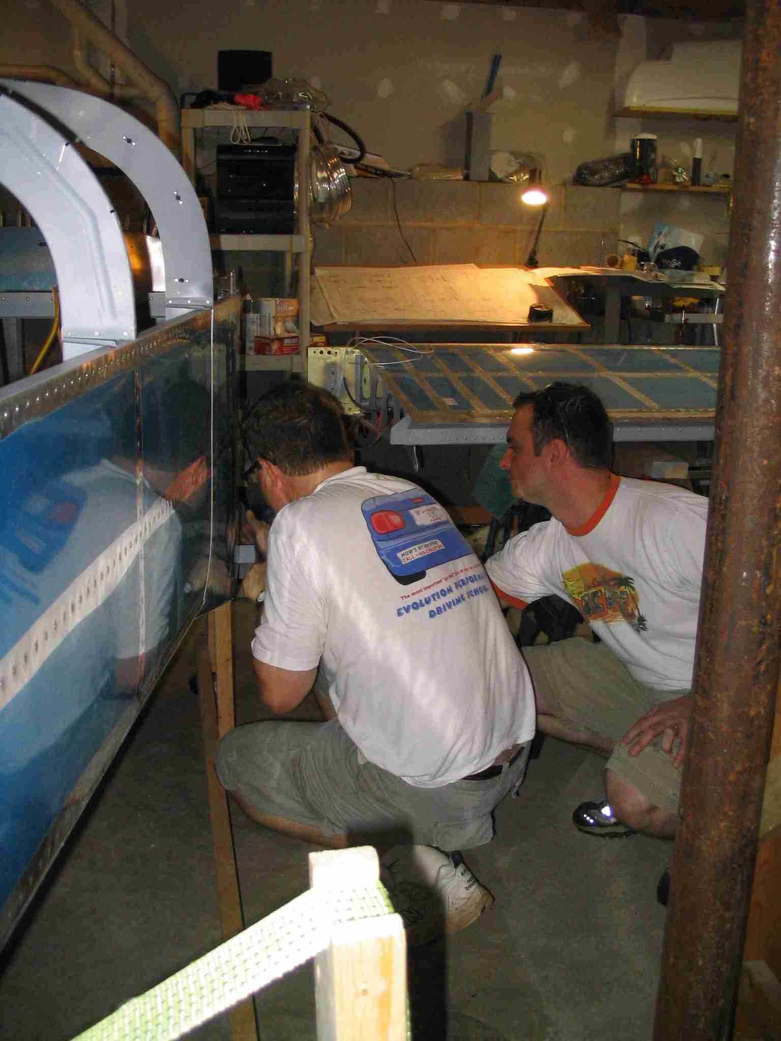
Tad Sargent is waxing the left wing spar stub with BoLube so
it will slide right in to place. We also waxed the pins
we used to temporarily hold the wings in place. (10/2/05) E
Tad Sargent is waxing the left wing spar stub with BoLube so
it will slide right in to place. We also waxed the pins
we used to temporarily hold the wings in place. (10/2/05) |
| |
|
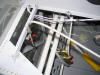
 F
Here I'm marking the aft spar stub for edge clearance before
inserting into the fuselage. (10/2/05) F
Here I'm marking the aft spar stub for edge clearance before
inserting into the fuselage. (10/2/05) |
| |
|
 E
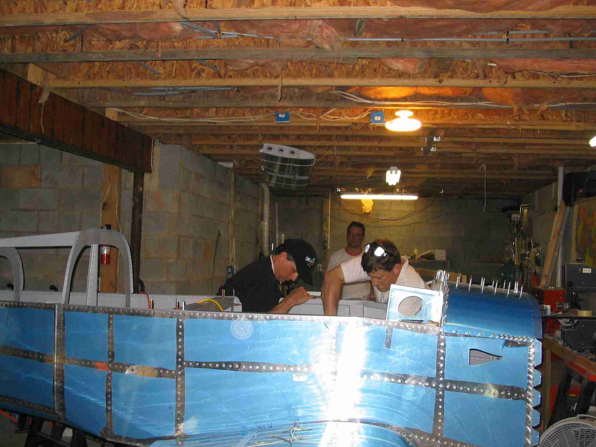
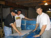
Tad, Radomir Zaric, and myself are installing the left wing.
It doesn't take long to install the wings. What will
take some time is lining wthing up in preparation for
drilling the hole in the aft spar. Once that is
completed the flaps, ailerons, wing tips, pitot tube, wiring,
and wing tips will all need to be installed before removing
and storing the wings until final assembly at the airport.
Much thanks go out to Tad (RV-7A builder and almost flier), Radomir (RV-7A builder) for their help, and to Andy
Moscarelli, Tech Adviser and RV-6A flier, who proved moral
support via the telephone and email. E
Tad, Radomir Zaric, and myself are installing the left wing.
It doesn't take long to install the wings. What will
take some time is lining wthing up in preparation for
drilling the hole in the aft spar. Once that is
completed the flaps, ailerons, wing tips, pitot tube, wiring,
and wing tips will all need to be installed before removing
and storing the wings until final assembly at the airport.
Much thanks go out to Tad (RV-7A builder and almost flier), Radomir (RV-7A builder) for their help, and to Andy
Moscarelli, Tech Adviser and RV-6A flier, who proved moral
support via the telephone and email.
The wings slide right in and very
little adjustment will be needed before drilling the aft spar.
Tad recommended I wait a day for everything to settle down
before drilling the aft spar and I agree with him.
Tomorrow I will verify that everything is level and the wings
are in the correct place before I drill them to the fuselage.
Based on the preliminary measurements we made this morning,
the wings lined up perfectly. Thanks Van's for such a
great kit! (10/2/05) |
| |
|
 F
Here it is with the wings on for the first time! (10/2/05) F
Here it is with the wings on for the first time! (10/2/05) |
| |
|
 E
The day after we installed the wings I stopped by the ABF
freight terminal and picked up the finishing kit. That
is the largest box of all and yes, it will fill the bed of a
standard size pickup. (10/3/05) E
The day after we installed the wings I stopped by the ABF
freight terminal and picked up the finishing kit. That
is the largest box of all and yes, it will fill the bed of a
standard size pickup. (10/3/05) |
| |
|
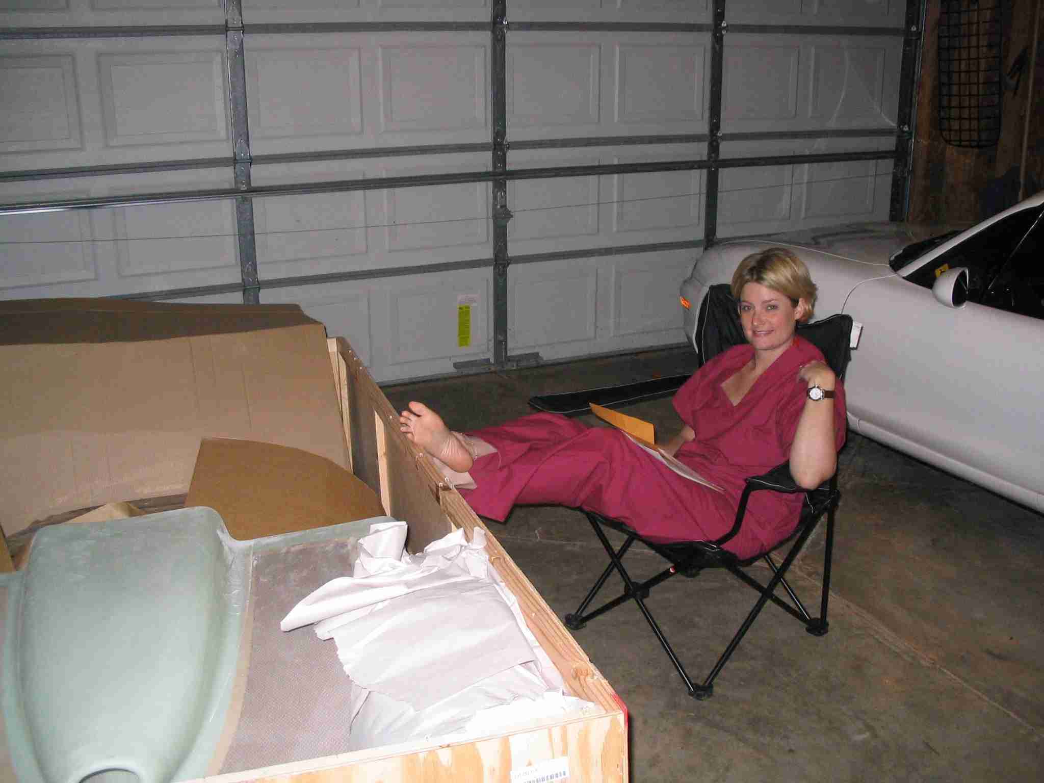
 F
Here is the good Doctor helping me inventory the kit.
Big box, short list. The inventory list for the
finishing kit is only three pages long so it went quickly.
After moving all the parts down into the basement I will need
to break down the big crate so she can get her trucklet back
in the garage. (10/4/05) F
Here is the good Doctor helping me inventory the kit.
Big box, short list. The inventory list for the
finishing kit is only three pages long so it went quickly.
After moving all the parts down into the basement I will need
to break down the big crate so she can get her trucklet back
in the garage. (10/4/05) |
| |
|
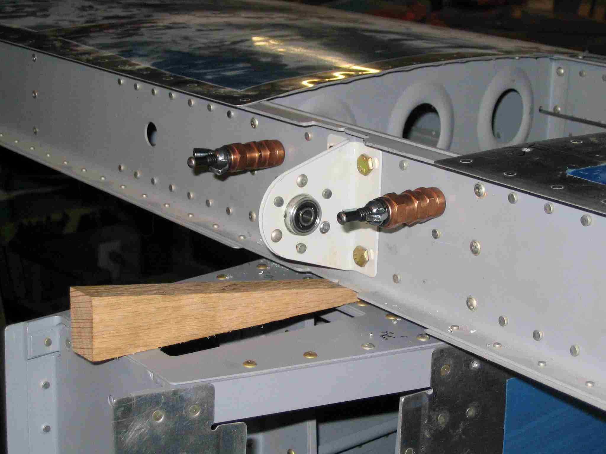
   E
After installing the wings on Sunday I waited until Friday
night to drill the aft spar. Yes, it took me that long
to get up the nerve. Before drilling yours, go to the
FAQ page on Van's web site and get the directions posted
there. They are much better than the instructions
included in the manual. Nora helped square up the wing
and everything came out just perfect. The Smart Level
was reading zeros all the way around and the wings were square
so it was time to hold my breath and start drilling. I
used a small block of oak with a perpendicular hole drilled in
it as a drill guide. Of course this only worked after
measuring for proper edge distance, punching the bracket, and
starting the hole free hand. The starter hole allowed me
to put the block in the correct place with the drill bit
sticking out just a little bit. (10/7/05) E
After installing the wings on Sunday I waited until Friday
night to drill the aft spar. Yes, it took me that long
to get up the nerve. Before drilling yours, go to the
FAQ page on Van's web site and get the directions posted
there. They are much better than the instructions
included in the manual. Nora helped square up the wing
and everything came out just perfect. The Smart Level
was reading zeros all the way around and the wings were square
so it was time to hold my breath and start drilling. I
used a small block of oak with a perpendicular hole drilled in
it as a drill guide. Of course this only worked after
measuring for proper edge distance, punching the bracket, and
starting the hole free hand. The starter hole allowed me
to put the block in the correct place with the drill bit
sticking out just a little bit. (10/7/05) |
| |
|
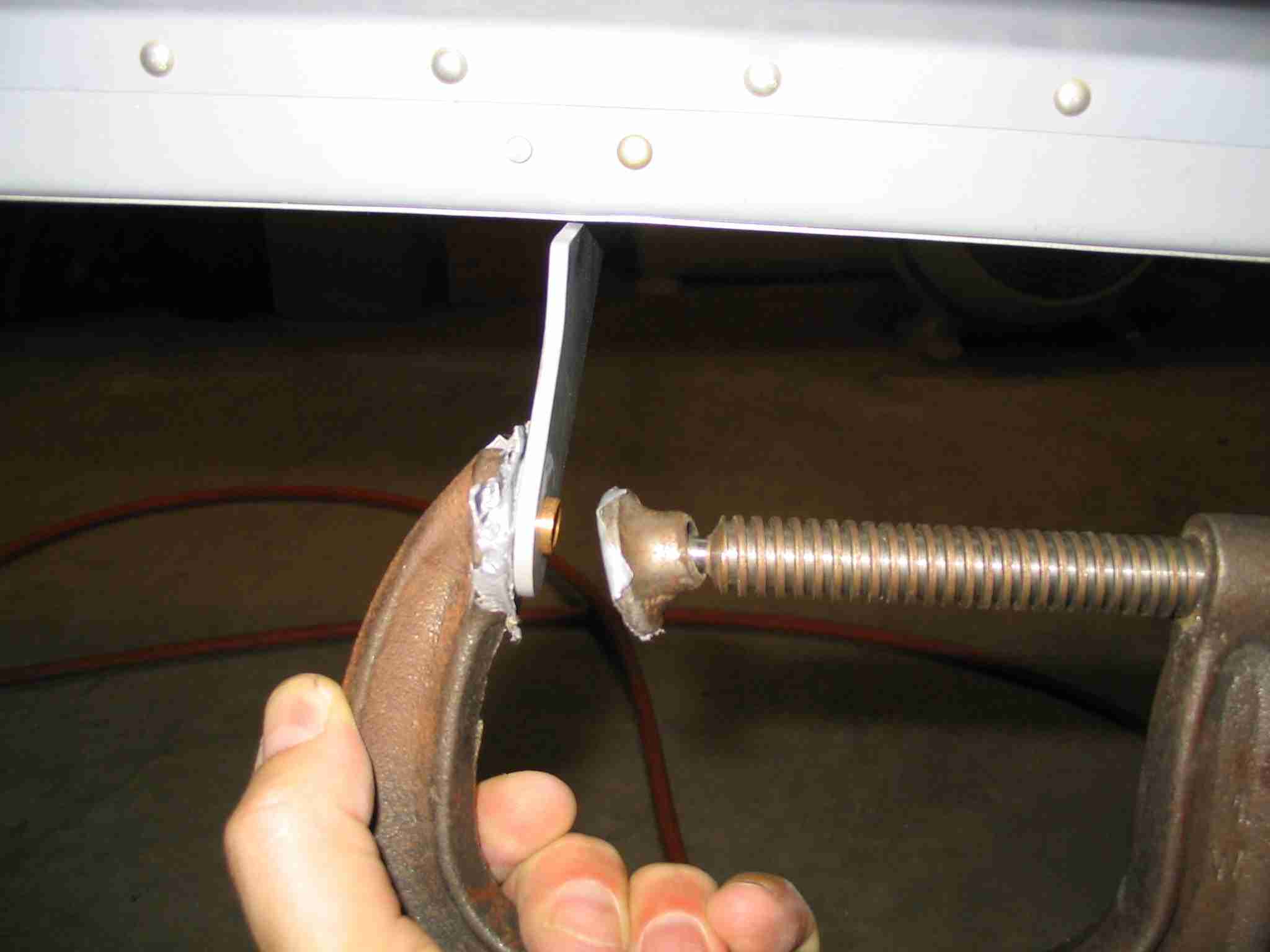
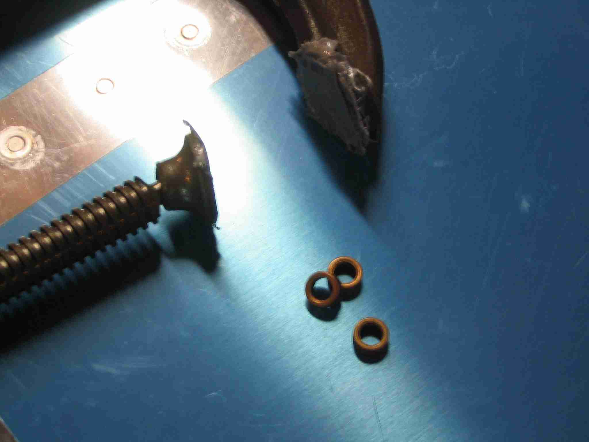
  F
Saturday was spent bending and fitting the fuel tank brackets,
sorry no pictures. The brackets are thick and it took a
lot of persuasion with a 10 lb sludge hammer and 2x4 to bend
them to the proper angle. Sunday found me back under the
fuselage cutting holes for the flap actuators and installing
the flaps. For some reason I never installed the small
bushings in the flap brackets located on the wings. To install them I used a
large C-clamp with the faces covered in duct tape. The
foot of the clamp was covered with about 10 layers of
duct tape and the screw side only had one layer. The one
layer of tape on the screw sized was to keep from scratching
the parts, the foot had multiple layers to allow the the
bearing to push past the side of the bracket just a little bit as
they are thicker than the bracket and should "stand proud" of
both surfaces. The extra tape allowed this to happen. (10/8/05) F
Saturday was spent bending and fitting the fuel tank brackets,
sorry no pictures. The brackets are thick and it took a
lot of persuasion with a 10 lb sludge hammer and 2x4 to bend
them to the proper angle. Sunday found me back under the
fuselage cutting holes for the flap actuators and installing
the flaps. For some reason I never installed the small
bushings in the flap brackets located on the wings. To install them I used a
large C-clamp with the faces covered in duct tape. The
foot of the clamp was covered with about 10 layers of
duct tape and the screw side only had one layer. The one
layer of tape on the screw sized was to keep from scratching
the parts, the foot had multiple layers to allow the the
bearing to push past the side of the bracket just a little bit as
they are thicker than the bracket and should "stand proud" of
both surfaces. The extra tape allowed this to happen. (10/8/05) |
| |
|
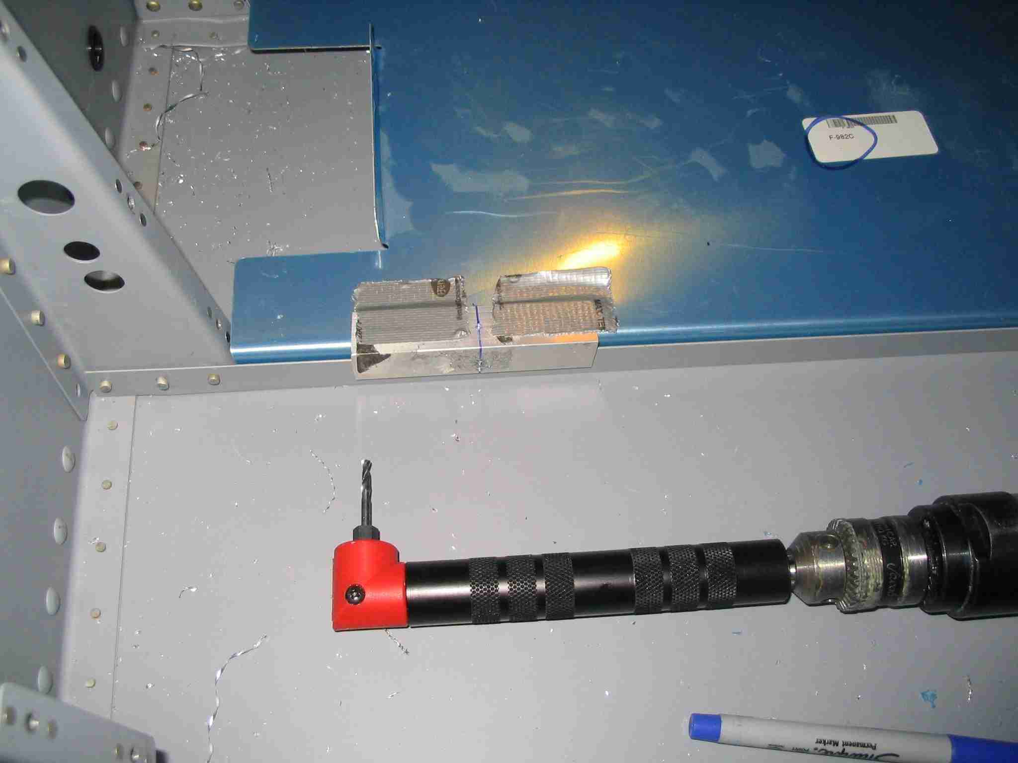
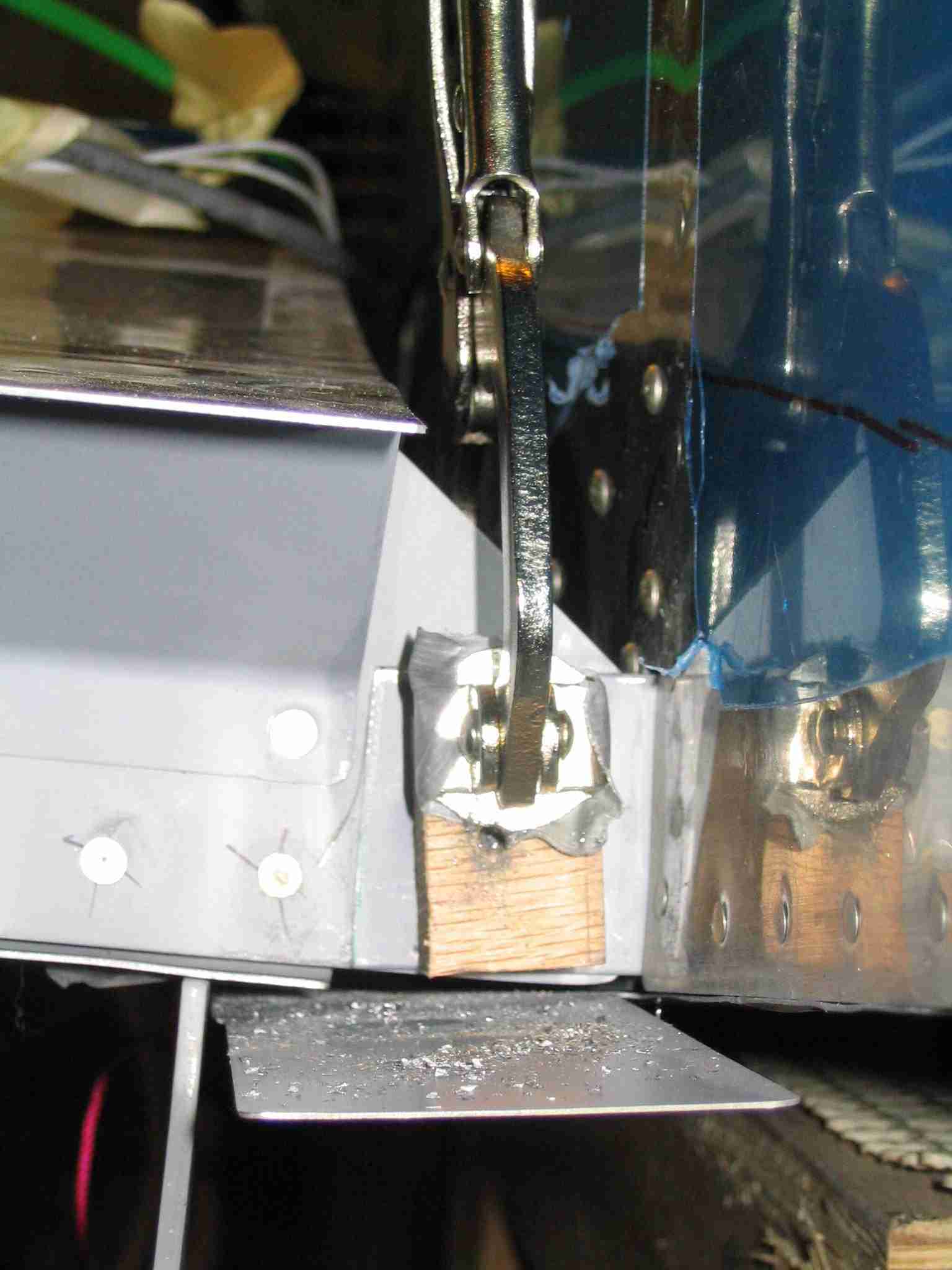
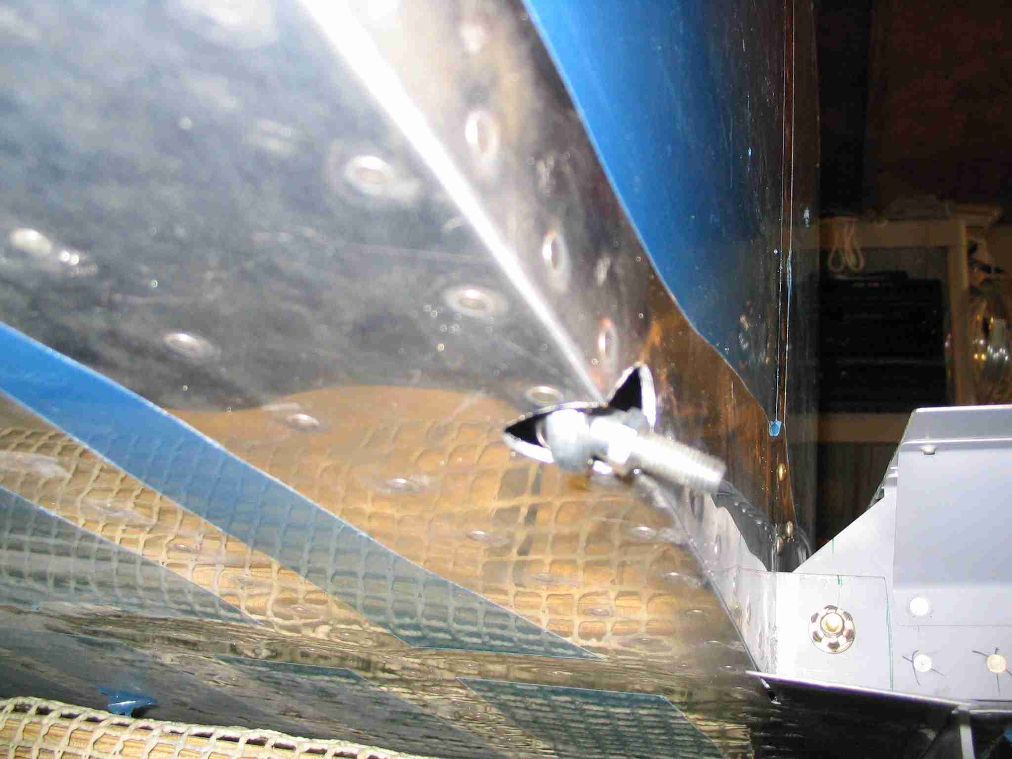
   E
Installing the flaps was straightforward. The only real
issue is cutting the hole in the side of the fuselage to allow
the flap actuator push rode bearing end to retract all the way
into the fuselage. Here is how my hole came out.
Your mileage may very. This is definitely a file a
little, test fit, file a little, test fit it exercise.
(10/8/05) E
Installing the flaps was straightforward. The only real
issue is cutting the hole in the side of the fuselage to allow
the flap actuator push rode bearing end to retract all the way
into the fuselage. Here is how my hole came out.
Your mileage may very. This is definitely a file a
little, test fit, file a little, test fit it exercise.
(10/8/05) |
| |
|
 F
Installing both ailerons with Nora's help. Had to dig
out the wing drawings to do this so keep those things handy.
Nora sat in the cockpit and made airplane noises while I was
flat on my back under the wing adjusting the push tubes.
(10/11/05) F
Installing both ailerons with Nora's help. Had to dig
out the wing drawings to do this so keep those things handy.
Nora sat in the cockpit and made airplane noises while I was
flat on my back under the wing adjusting the push tubes.
(10/11/05) |
| |
|
 E
The HS is now installed. This was an easy task and
setting the incidence isn't a big deal according to Van's.
However, I wanted to make sure it was perfect so I used this
little bit of wedge to raise the back of the HS to the proper
position. Installing two long drill bits in the tooling
holes of the inboard ribs allowed me to measure from the deck
to the bottom of the drill bit, thus assuring the incidence
was set correctly.
(10/22/05) E
The HS is now installed. This was an easy task and
setting the incidence isn't a big deal according to Van's.
However, I wanted to make sure it was perfect so I used this
little bit of wedge to raise the back of the HS to the proper
position. Installing two long drill bits in the tooling
holes of the inboard ribs allowed me to measure from the deck
to the bottom of the drill bit, thus assuring the incidence
was set correctly.
(10/22/05) |
| |
|
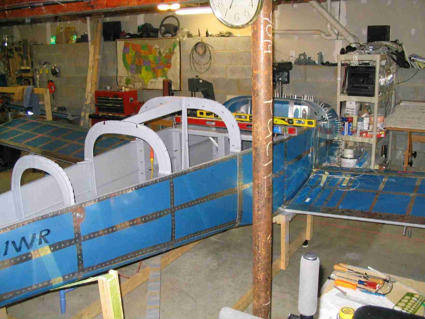
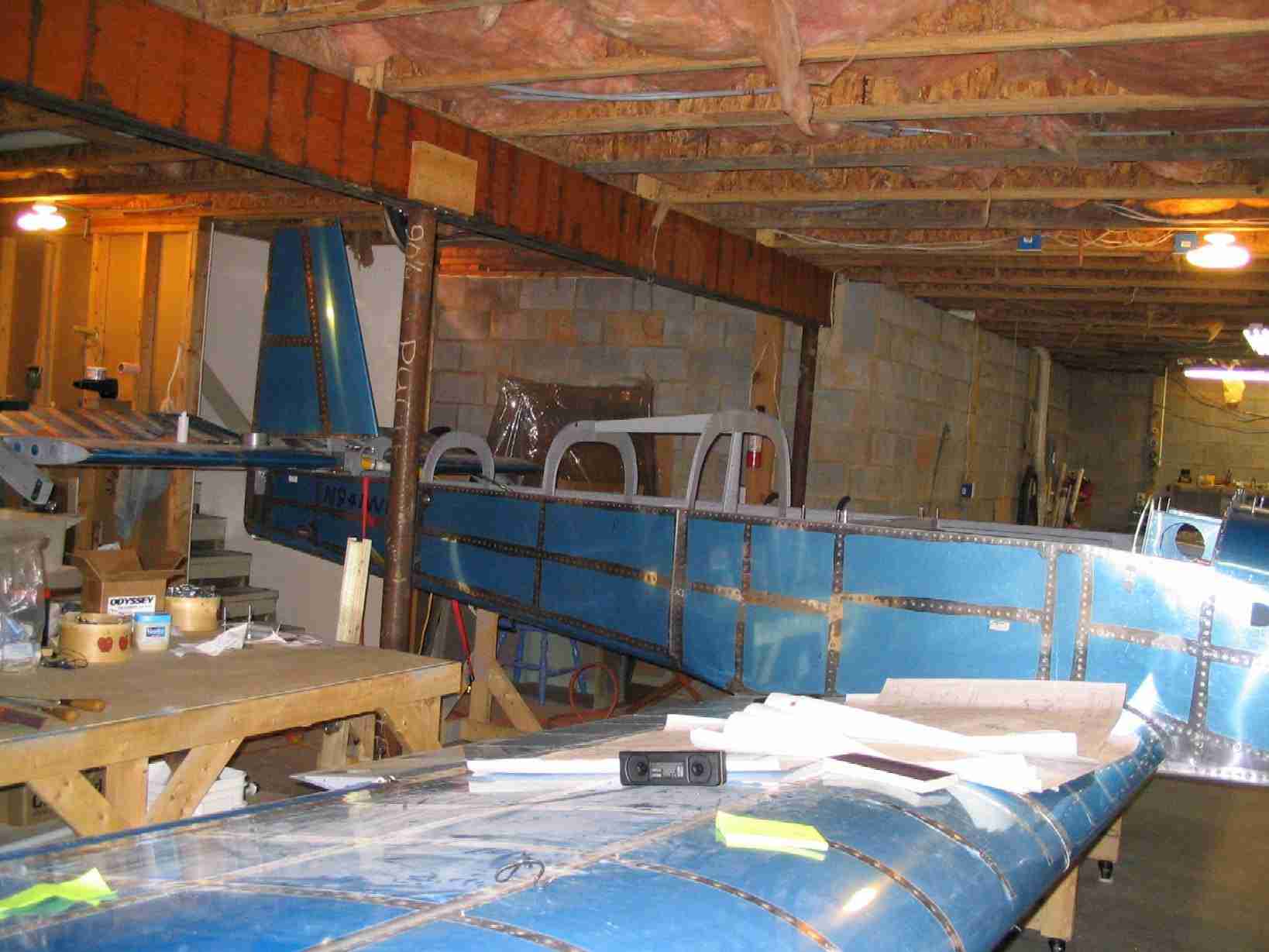
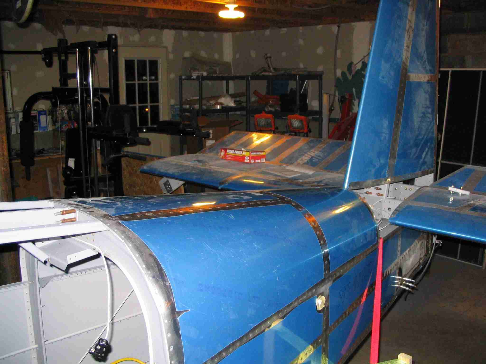
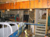
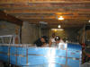
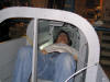
 F
In case you were wondering, a completed RV-9 can fit in a
basement with room to walk around. Well sort of walk
around, I do have to duck under the HS. The sticks are
in and the ailerons and elevator are now functional. I
did not run the trim cable through the HS and attach it to the
trim tab as it might make disassembly the plane difficult and
I do have to get this thing out of my basement at some point.
The next task will be to drill the VS and install the rudder. (10/26/05) F
In case you were wondering, a completed RV-9 can fit in a
basement with room to walk around. Well sort of walk
around, I do have to duck under the HS. The sticks are
in and the ailerons and elevator are now functional. I
did not run the trim cable through the HS and attach it to the
trim tab as it might make disassembly the plane difficult and
I do have to get this thing out of my basement at some point.
The next task will be to drill the VS and install the rudder. (10/26/05) |
| |
|
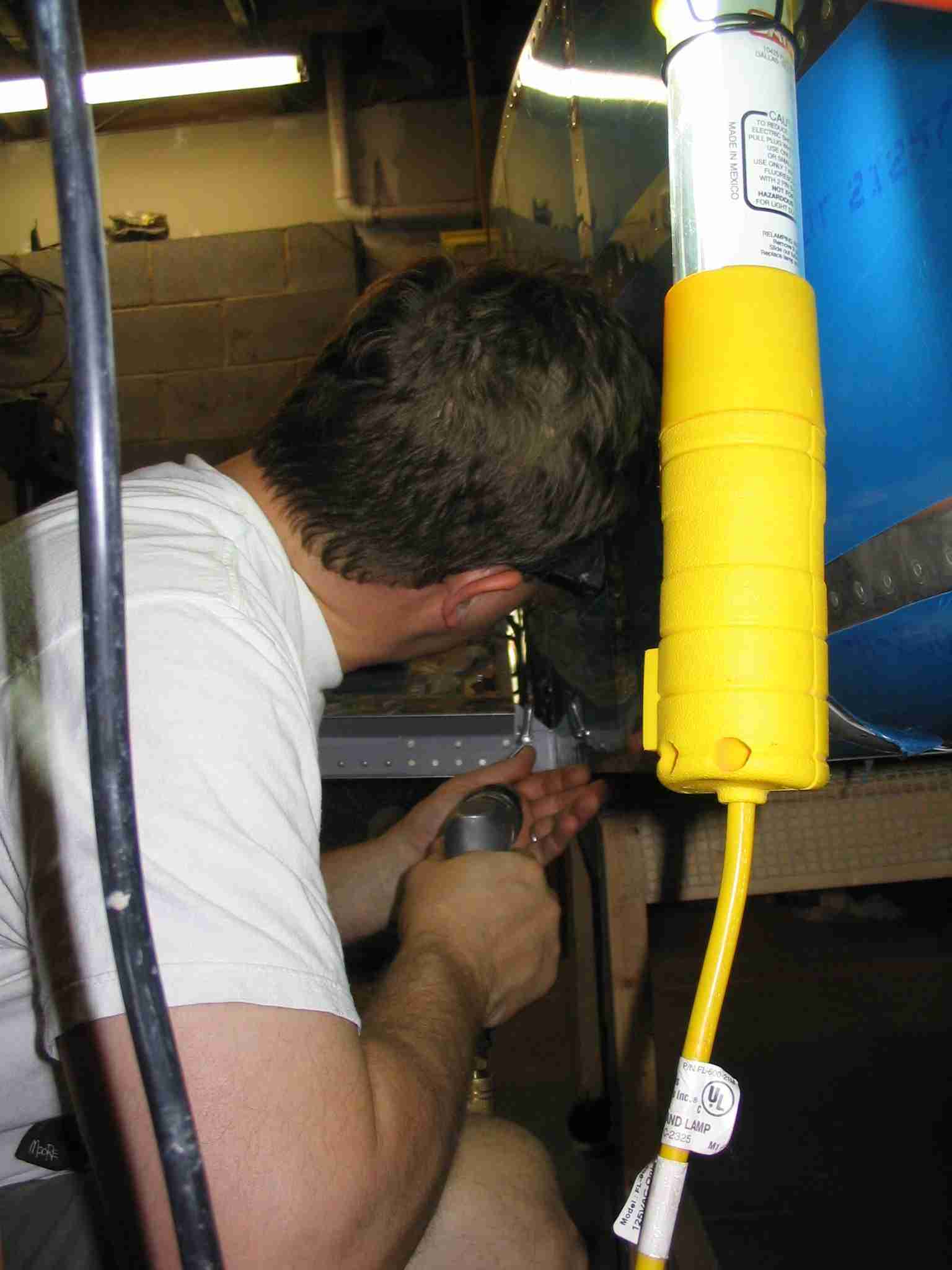
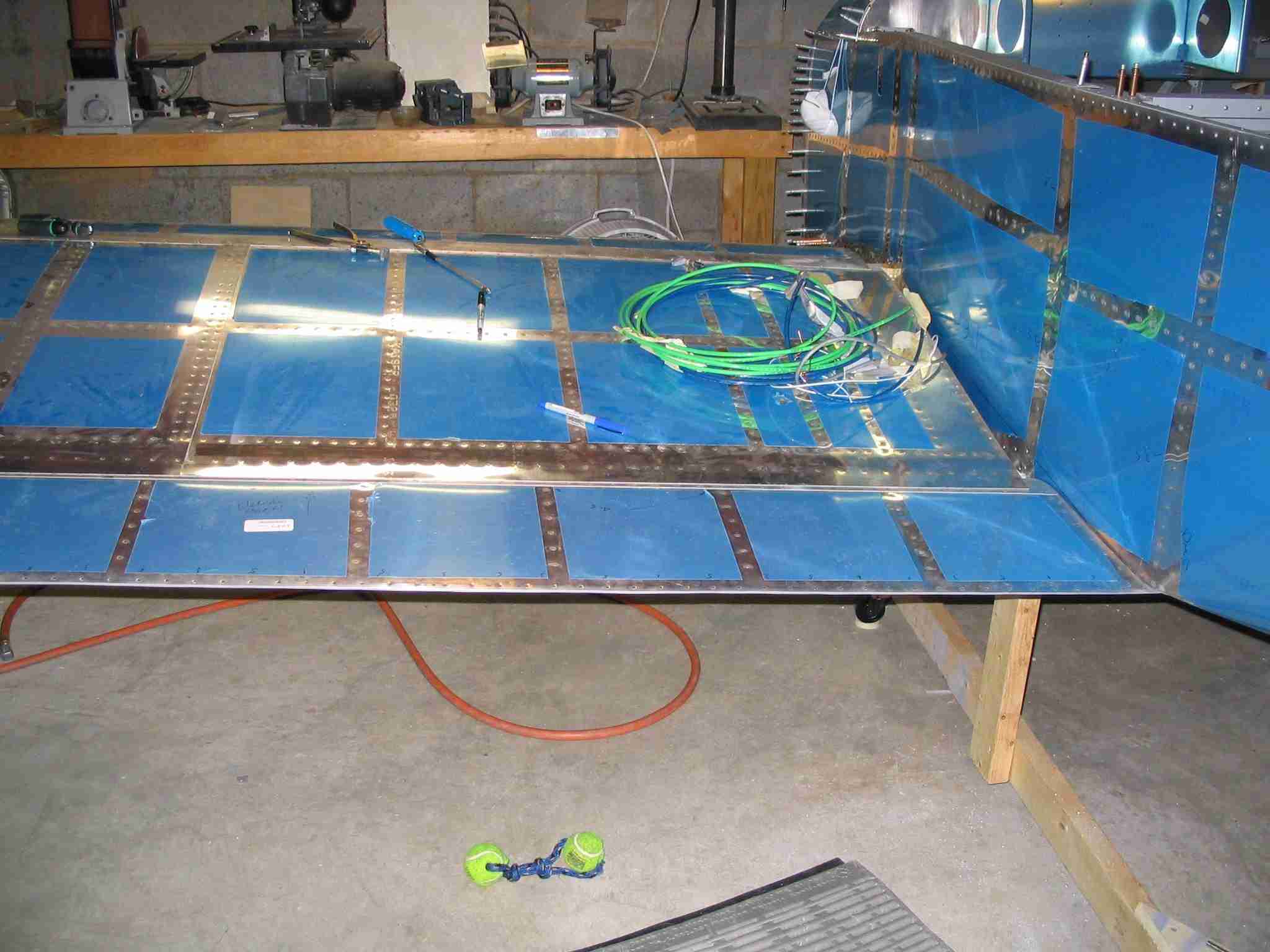
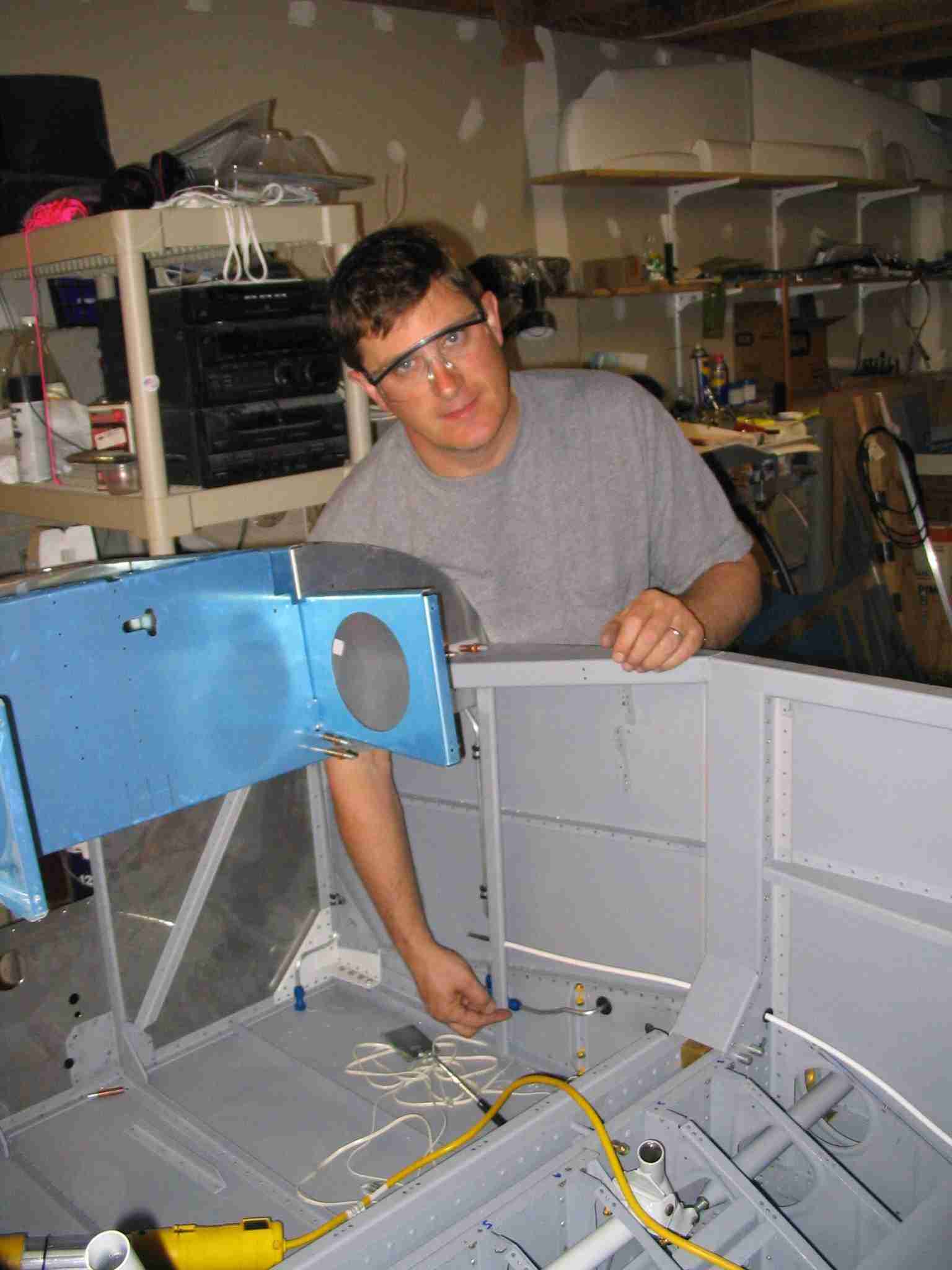
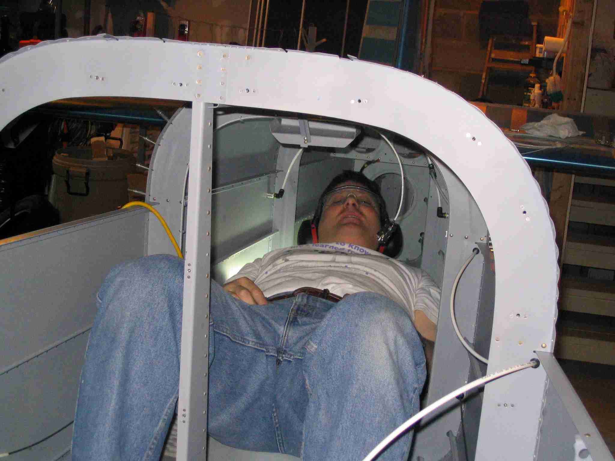
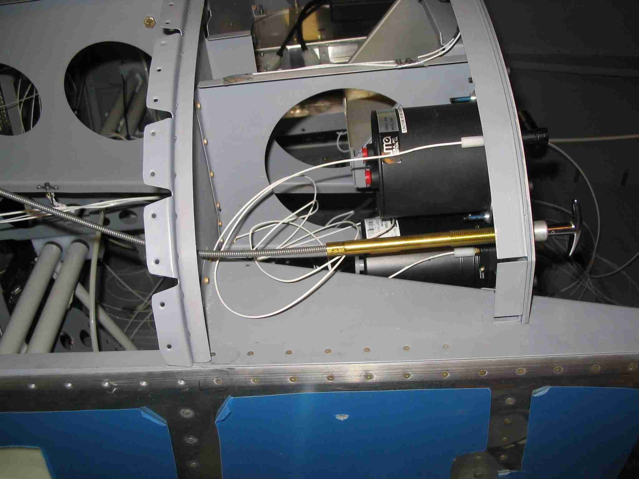
 E
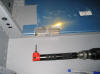
Now that the wings are on I'm spending time hooking everything
up to them so they can be removed and put in storage so I will
have room to work on the aircraft systems. Here is a
picture of me installing the vent line for the right fuel
tank. Since this picture was taken the left vent and
fuel lines have been installed. I buggered up the right
fuel line and am waiting for replacement tubing to arrive so I
can finish the right fuel line. Although the lines go
through the side of fuselage there is no room to flair them
with the wing on so my plan is to mark the lines with the wing
on so I will know where to cut them. After the wing is
removed, the fuel and vent lines will be cut to length and
flared. It should be noted that at the end of each
working session I put some tape over the open fuel (and pitot
and static lines) to keep bugs out during construction.
(11/15/05) E
Now that the wings are on I'm spending time hooking everything
up to them so they can be removed and put in storage so I will
have room to work on the aircraft systems. Here is a
picture of me installing the vent line for the right fuel
tank. Since this picture was taken the left vent and
fuel lines have been installed. I buggered up the right
fuel line and am waiting for replacement tubing to arrive so I
can finish the right fuel line. Although the lines go
through the side of fuselage there is no room to flair them
with the wing on so my plan is to mark the lines with the wing
on so I will know where to cut them. After the wing is
removed, the fuel and vent lines will be cut to length and
flared. It should be noted that at the end of each
working session I put some tape over the open fuel (and pitot
and static lines) to keep bugs out during construction.
(11/15/05) |
| |
|
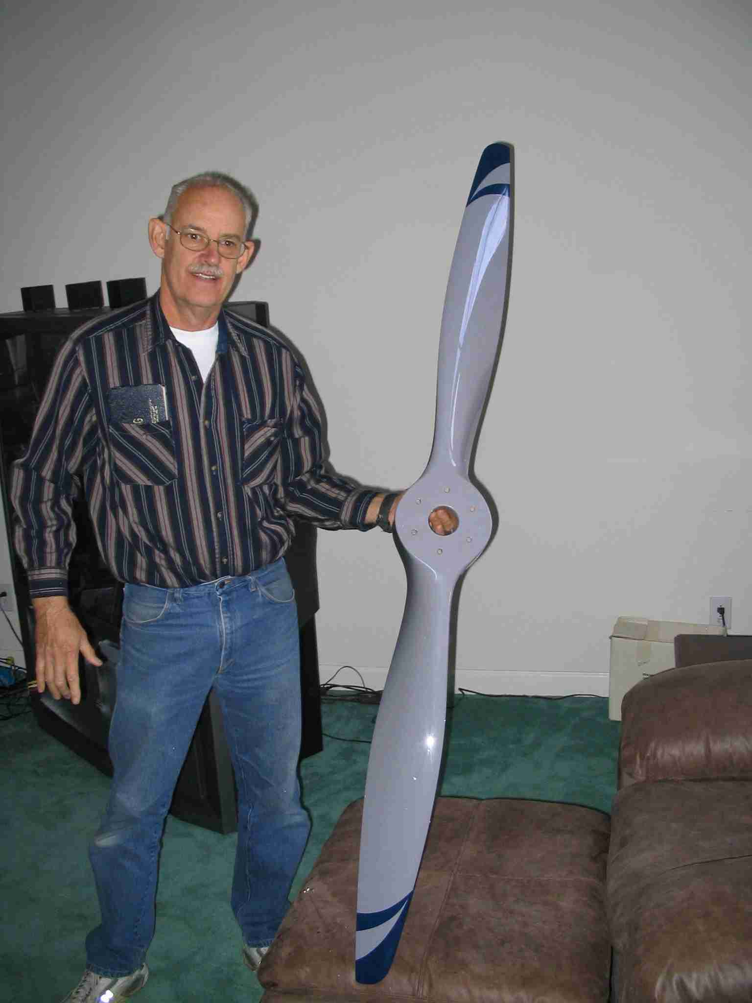
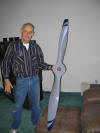 F
As Larry Turner and I sate down for lunch on November 25th the
door bell rang. As leapt from my chair to see what was
the matter, when what did my wondering eyes did appear but US
Postman with an enormous box. Actually, it wasn't that
large but it did contain my Catto prop and it was a thing of
beauty. I can't wait to fly behind this thing.
After opening it and realizing I didn't have a place to put it
and knowing Larry and I had to leave ASAP I took the prop up
to the bedroom and tucked in bed thinking Nora would find it
there before I returned. (11/25/05) F
As Larry Turner and I sate down for lunch on November 25th the
door bell rang. As leapt from my chair to see what was
the matter, when what did my wondering eyes did appear but US
Postman with an enormous box. Actually, it wasn't that
large but it did contain my Catto prop and it was a thing of
beauty. I can't wait to fly behind this thing.
After opening it and realizing I didn't have a place to put it
and knowing Larry and I had to leave ASAP I took the prop up
to the bedroom and tucked in bed thinking Nora would find it
there before I returned. (11/25/05) |
| |
|
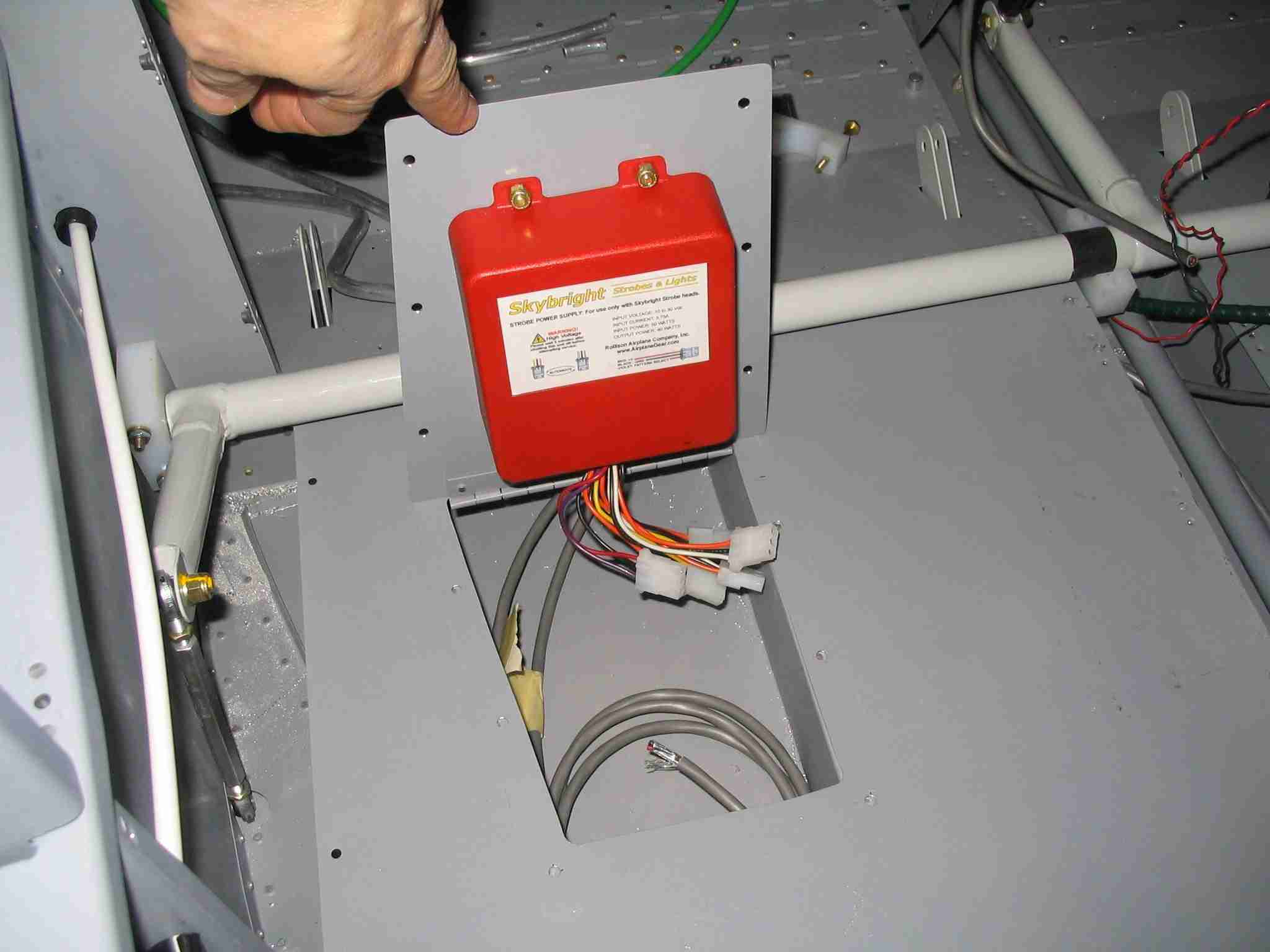
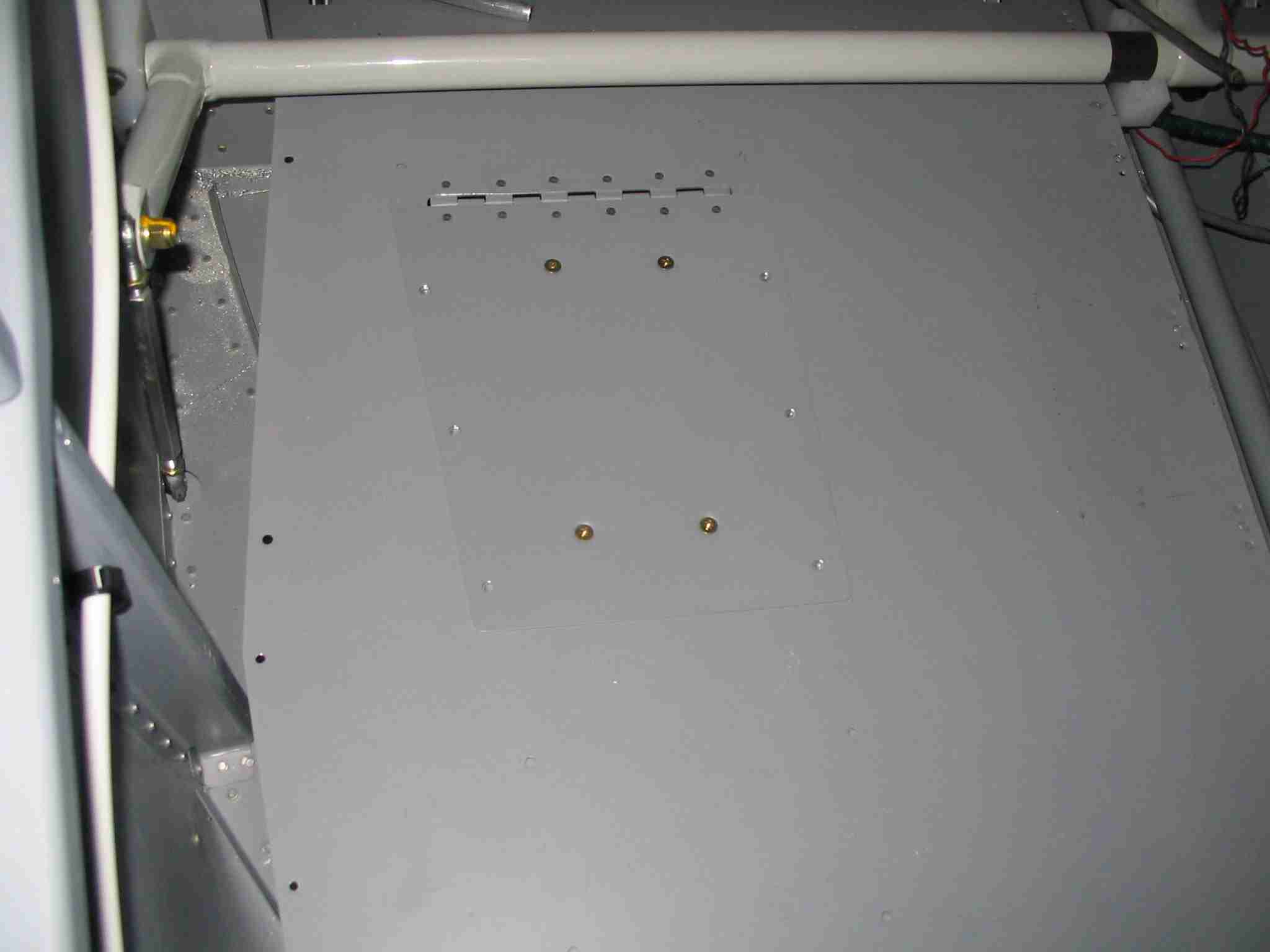
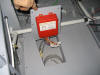  E
One of the major issues the RV-7A's have is a propensity
towards being tail heavy. Since I'm using a lighter
engine in my -9 I have made every effort to keep all my gear
in the center of the airplane. On 8/9/05 I posted that I
installed the ELT on the right side, under the baggage
compartment floor. When it came time to mount the strobe
power supply I did the same thing, I mounted it under the left
side of the baggage compartment floor. Both the ELT and
strobe power supply doors were made from a trashed wing tank
skin I had laying around, just don't ask why I had it laying
around. Some builders have attached the baggage floor
with plate nuts. Although I like this idea, that does
add weight and my goal is get my -9's empty weight as close to
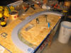
1,000 lbs as I can. (11/27/05) E
One of the major issues the RV-7A's have is a propensity
towards being tail heavy. Since I'm using a lighter
engine in my -9 I have made every effort to keep all my gear
in the center of the airplane. On 8/9/05 I posted that I
installed the ELT on the right side, under the baggage
compartment floor. When it came time to mount the strobe
power supply I did the same thing, I mounted it under the left
side of the baggage compartment floor. Both the ELT and
strobe power supply doors were made from a trashed wing tank
skin I had laying around, just don't ask why I had it laying
around. Some builders have attached the baggage floor
with plate nuts. Although I like this idea, that does
add weight and my goal is get my -9's empty weight as close to
1,000 lbs as I can. (11/27/05) |
| |
|
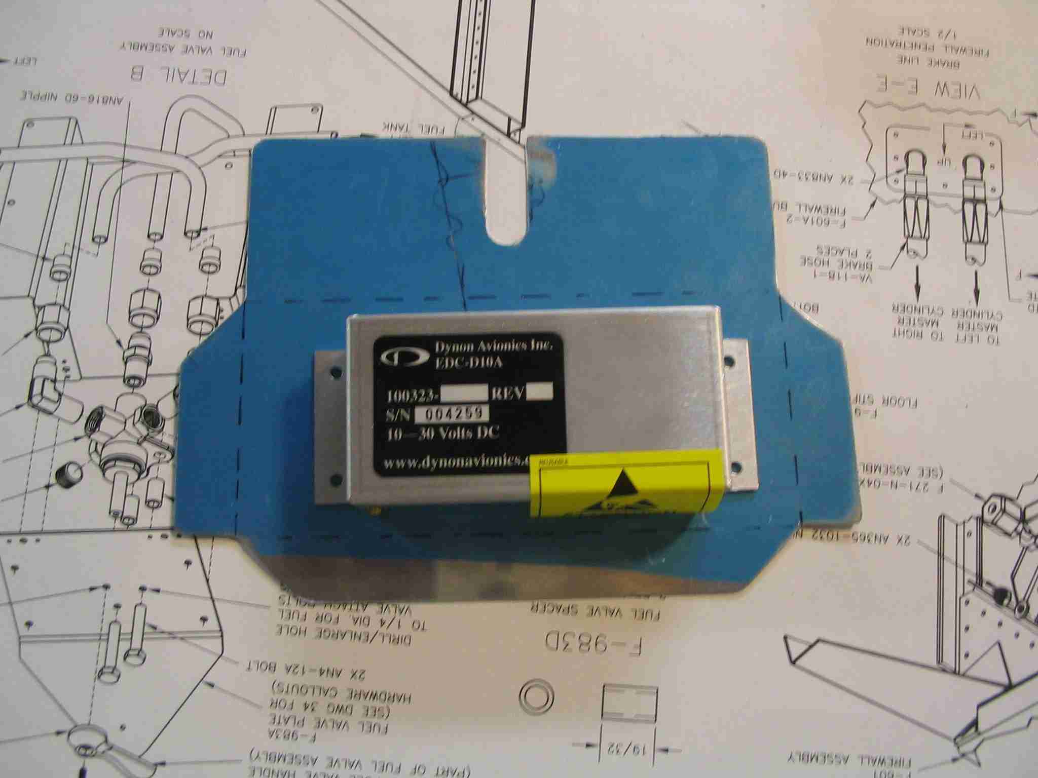
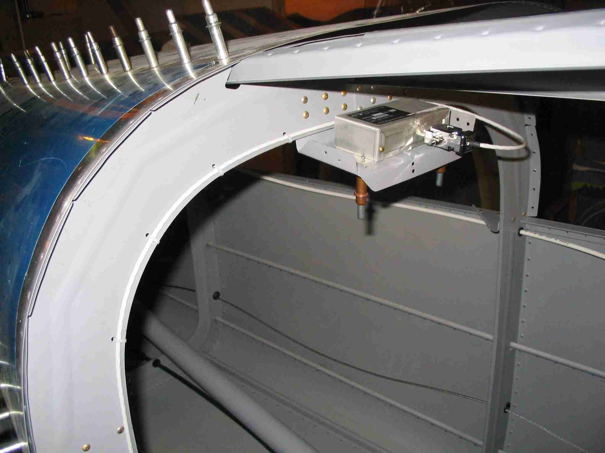
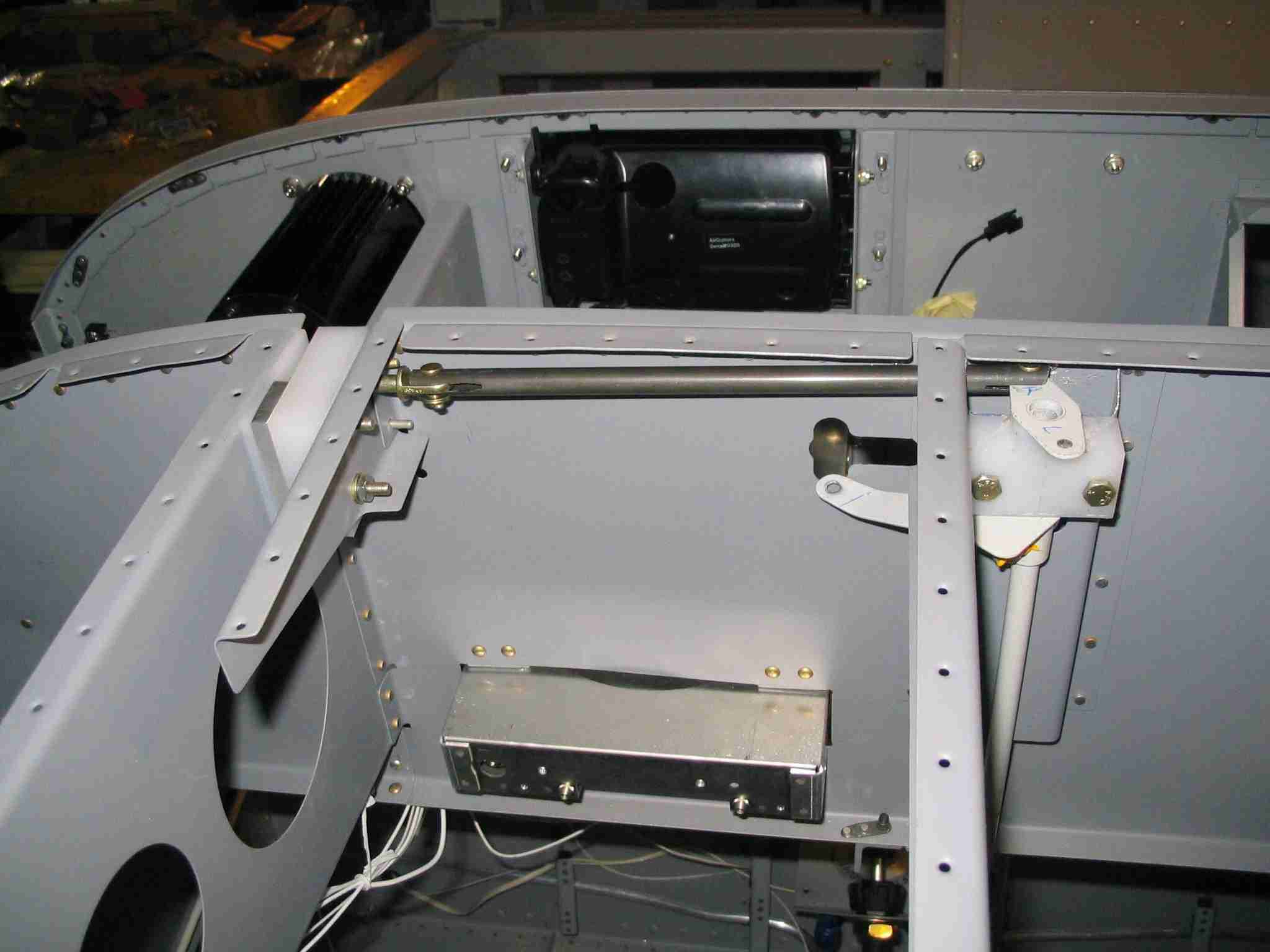
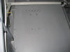
 F
The Dynon D100 EFIS that will reside in the middle of N941WR's
instrument panel requires a remote compass. Although it
is a small unit, it needs to be mounted away from any ferrous
metal. Including some that you might put in the baggage
compartment. My solution was to mount close the top of
the aircraft at the 2nd bulkhead behind the baggage
compartment. The picture shows the mounting tray I
fabricated to hold it. (1/21/06) F
The Dynon D100 EFIS that will reside in the middle of N941WR's
instrument panel requires a remote compass. Although it
is a small unit, it needs to be mounted away from any ferrous
metal. Including some that you might put in the baggage
compartment. My solution was to mount close the top of
the aircraft at the 2nd bulkhead behind the baggage
compartment. The picture shows the mounting tray I
fabricated to hold it. (1/21/06) |
| |
|
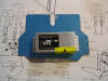
 E
I've been busy preparing for riveting the top skins on so I
can get to the roll bar and eventually the canopy.
Before those skins get riveted in place I want get everything
finished and cleaned up in the tail cone. This included
securing the tail light wires to the floor, making the bracket
to hold the Dynon remote compass, and routing the wires for
that compass. The compass bracket will have a short
section of "J" channel that will brace to the rib and keep it
from moving. (2/11/06) E
I've been busy preparing for riveting the top skins on so I
can get to the roll bar and eventually the canopy.
Before those skins get riveted in place I want get everything
finished and cleaned up in the tail cone. This included
securing the tail light wires to the floor, making the bracket
to hold the Dynon remote compass, and routing the wires for
that compass. The compass bracket will have a short
section of "J" channel that will brace to the rib and keep it
from moving. (2/11/06) |
| |
|
 F
After searching high and low for 8-32 screws with a "wing nut"
head that flips over flat and failing, I finally settled
on these screws from the aviation section at Lowes. If
any readers of this web site can locate screws with heads that
fold flat please let me know where I can find them. (2/16/06) F
After searching high and low for 8-32 screws with a "wing nut"
head that flips over flat and failing, I finally settled
on these screws from the aviation section at Lowes. If
any readers of this web site can locate screws with heads that
fold flat please let me know where I can find them. (2/16/06) |
| |
|
  E
It took close to three hours, most of it doing the final
fitting and bending the bulkhead flanges to the right angle,
cutting a board to fit in the tail cone, and stuffing my big 'ol
butt in such a small space but it was worth it the effort.
The upper aft tail cone skin is now riveted in place.
Much thanks to Radomir for his help driving those rivets. (2/26/06) E
It took close to three hours, most of it doing the final
fitting and bending the bulkhead flanges to the right angle,
cutting a board to fit in the tail cone, and stuffing my big 'ol
butt in such a small space but it was worth it the effort.
The upper aft tail cone skin is now riveted in place.
Much thanks to Radomir for his help driving those rivets. (2/26/06) |
| |
|
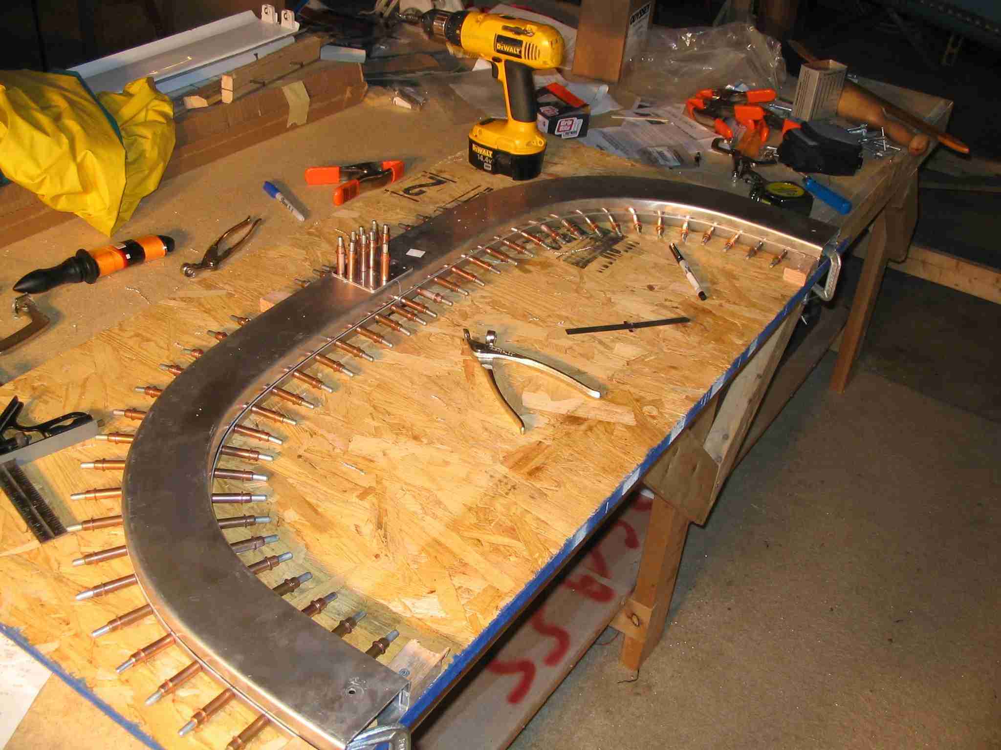
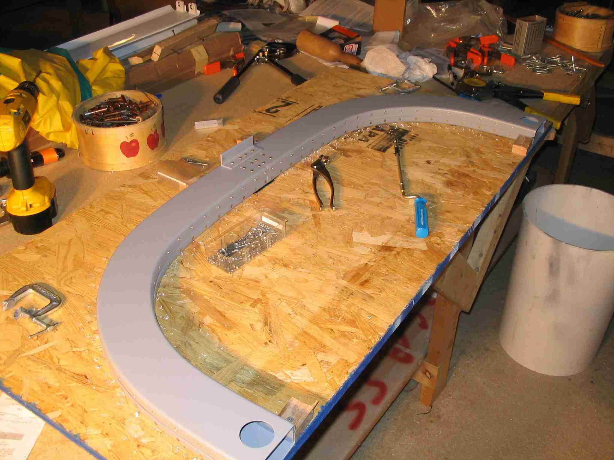
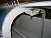
   F
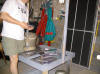
Building the tip-up roll bar is a bit of a chore. There
are 176 rivets in the thing and 160 of those must be
countersunk. To top it off, the thing can pull together
on you if you are not careful. I jigged mine so it
wouldn't move and after I pulled it out of the jig it still
moved together an 1/8 of an inch. Turns out it fit
perfect, which makes me wonder if Vans took this into account
when they designed it. In the third picture the roll bar
is just sitting in place, next up is drilling it to the
fuselage. (3/7/06) F
Building the tip-up roll bar is a bit of a chore. There
are 176 rivets in the thing and 160 of those must be
countersunk. To top it off, the thing can pull together
on you if you are not careful. I jigged mine so it
wouldn't move and after I pulled it out of the jig it still
moved together an 1/8 of an inch. Turns out it fit
perfect, which makes me wonder if Vans took this into account
when they designed it. In the third picture the roll bar
is just sitting in place, next up is drilling it to the
fuselage. (3/7/06) |
| |
|
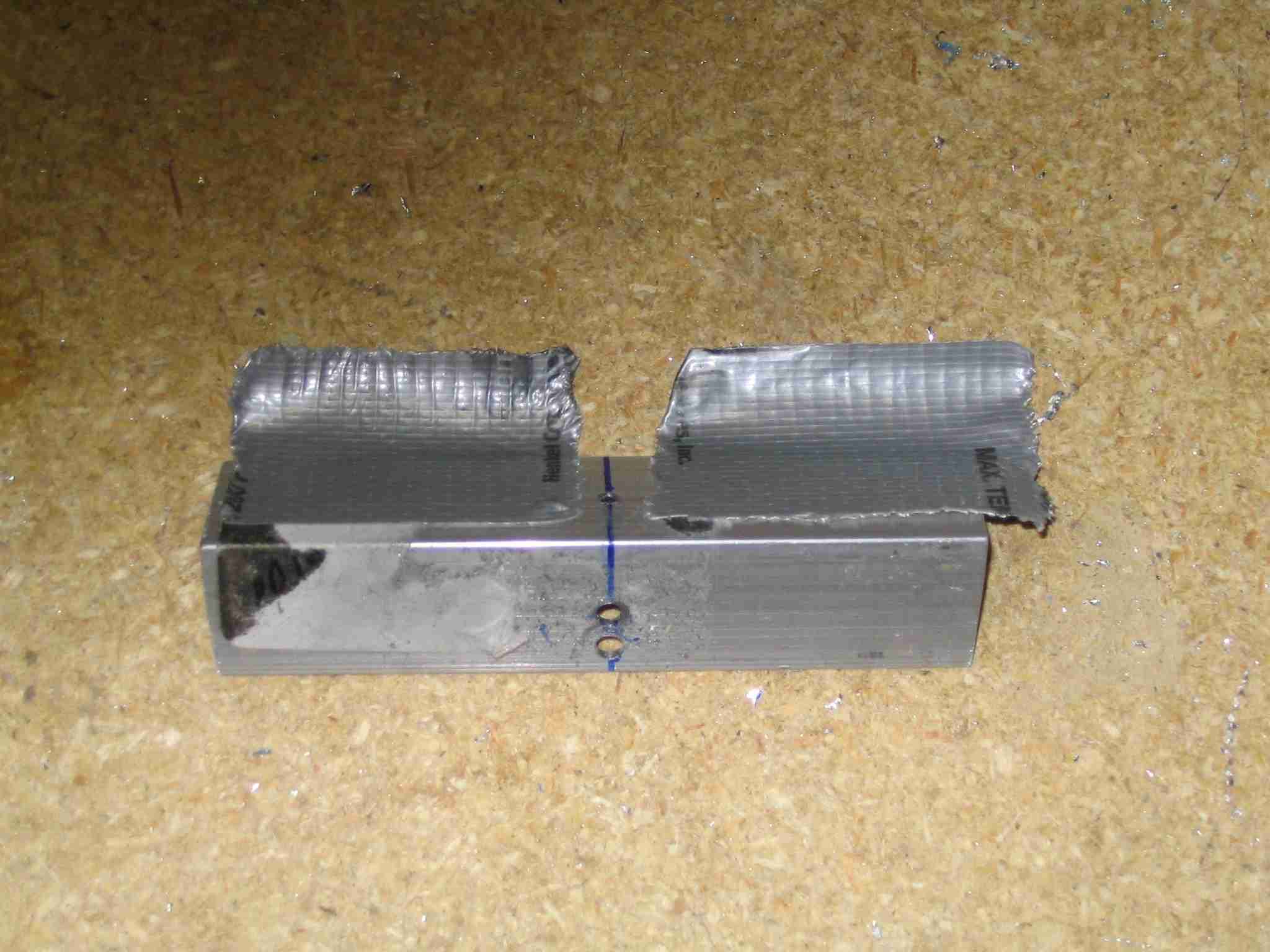
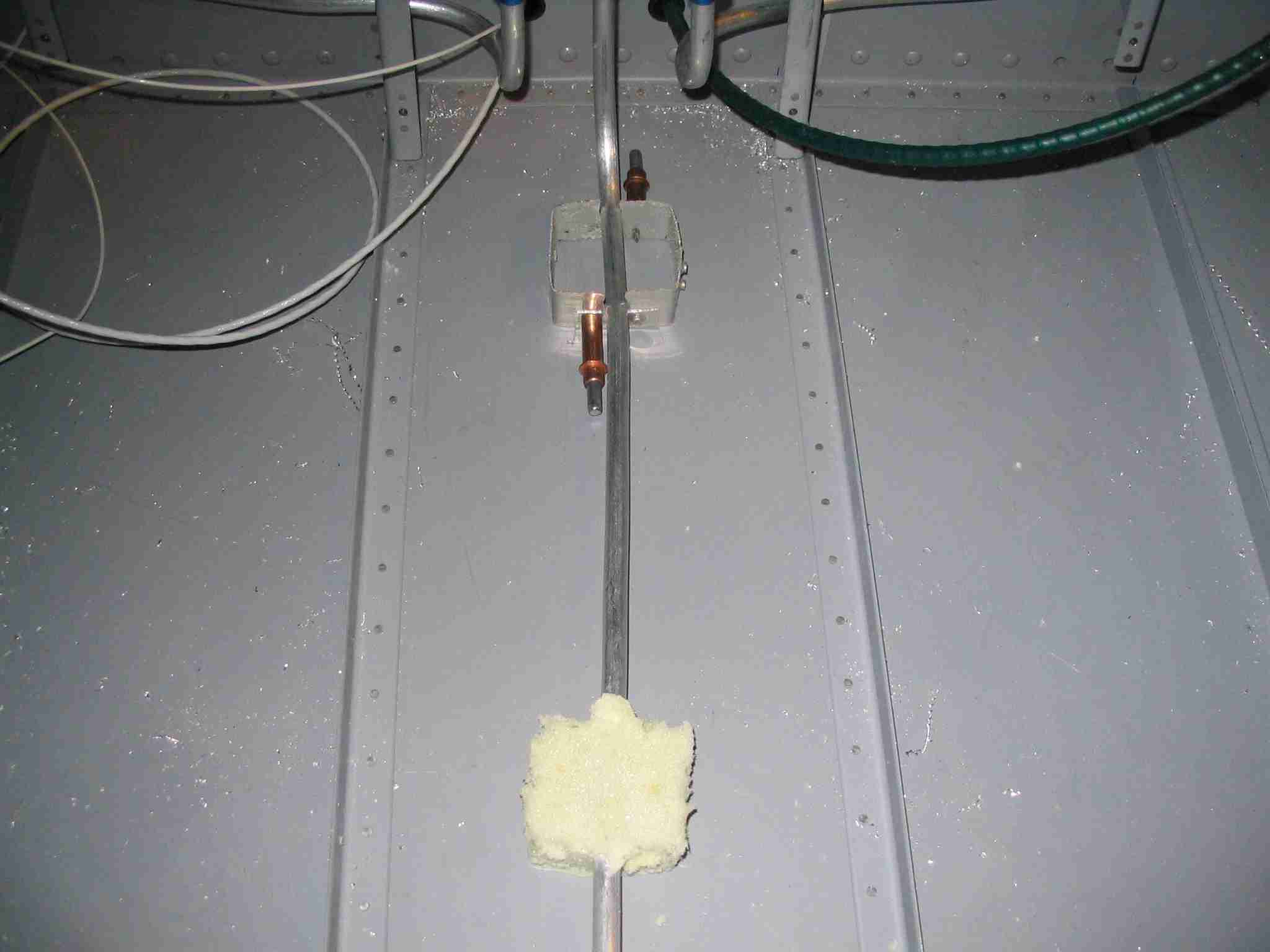
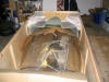
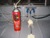  E
Somewhere the instructions tell you to support the fuel line
between the fuel selector valve and the fuel pump with foam.
I had thought long and hard about this and came up with the
idea of using self expanding insulation foam that comes in a
can. I built a simple two piece mold that would fit
around the fuel line and clamp together with two clecos.
The height of the mold was the same as the inside height of
the tunnel cover. Once in place I filled it with "Great
Stuff" self expanding foam. I cut the top off with a
hacksaw blade after the foam hardened and removed the mold.
This process was repeated three times and the foam blocks seem
to do a great job of holding the fuel line in place.
After the first block (blob?) hardened, I took the top I cut
off and dumped gas over the top of it to see if it would melt
like Styrofoam. That was not the case, your mileage may
very. Either way, I don't expect to have fuel in my
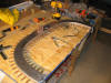
floorboards. (3/13/06) E
Somewhere the instructions tell you to support the fuel line
between the fuel selector valve and the fuel pump with foam.
I had thought long and hard about this and came up with the
idea of using self expanding insulation foam that comes in a
can. I built a simple two piece mold that would fit
around the fuel line and clamp together with two clecos.
The height of the mold was the same as the inside height of
the tunnel cover. Once in place I filled it with "Great
Stuff" self expanding foam. I cut the top off with a
hacksaw blade after the foam hardened and removed the mold.
This process was repeated three times and the foam blocks seem
to do a great job of holding the fuel line in place.
After the first block (blob?) hardened, I took the top I cut
off and dumped gas over the top of it to see if it would melt
like Styrofoam. That was not the case, your mileage may
very. Either way, I don't expect to have fuel in my
floorboards. (3/13/06) |
| |
|
   F
The drawings depict four small steel bands that are used to
tie the rudder peddles to the rudder cables. The bands
are .050 thick, 1/2" wide and length unknown. You are to
make them whatever length works for you and your rudder
location. Before cutting the four steel parts I made two
aluminum ones and tried on the rudder peddles for size.
My sample pieces were made exactly the same length as the full
size drawing depicted and they worked out just fine. In
the center position the peddles are slightly forward. At
full deflection, left or right, they do not hit the firewall
and the rudder cable moves freely. Left to right the
pictures are: looking straight down on the peddles, (4/19/06) F
The drawings depict four small steel bands that are used to
tie the rudder peddles to the rudder cables. The bands
are .050 thick, 1/2" wide and length unknown. You are to
make them whatever length works for you and your rudder
location. Before cutting the four steel parts I made two
aluminum ones and tried on the rudder peddles for size.
My sample pieces were made exactly the same length as the full
size drawing depicted and they worked out just fine. In
the center position the peddles are slightly forward. At
full deflection, left or right, they do not hit the firewall
and the rudder cable moves freely. Left to right the
pictures are: looking straight down on the peddles, (4/19/06) |
| |
|
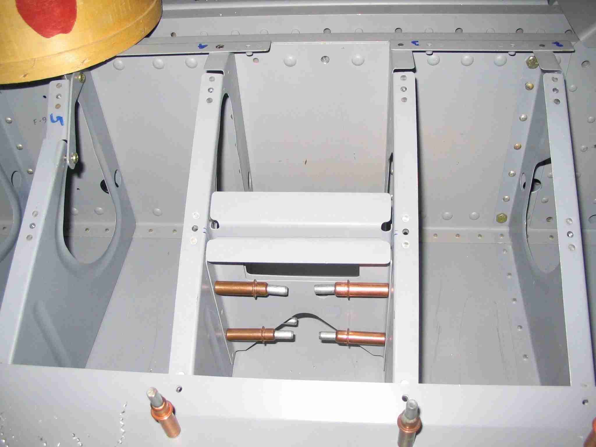
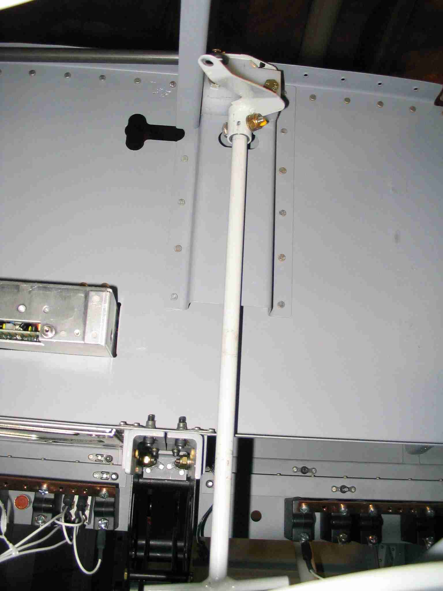
  E
Busy day. Cut and installed the right canopy release
pin, tube, and release mechanism. The "normal"
installation on a tip-up canopy is to run the emergency canopy
release handle aft and have it stick through the instrument
panel. Since the RV-9 is not acrobatic the chances of me
flying with a parachute and needing to exit the plane in a
hurry is very unlikely. Thus, I elected to install the
"T" handle vertically behind the forward sub-panel. To
release the canopy for maintenance, it will be necessary to
reach under the panel and twist the handle. The first
picture is of the "T" handle. The "T" part is the white
bar at the very bottom of the picture. The second
picture shows the right pin in the retracted position.
(The left pin is not installed in this picture.)
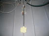
(4/23/06) E
Busy day. Cut and installed the right canopy release
pin, tube, and release mechanism. The "normal"
installation on a tip-up canopy is to run the emergency canopy
release handle aft and have it stick through the instrument
panel. Since the RV-9 is not acrobatic the chances of me
flying with a parachute and needing to exit the plane in a
hurry is very unlikely. Thus, I elected to install the
"T" handle vertically behind the forward sub-panel. To
release the canopy for maintenance, it will be necessary to
reach under the panel and twist the handle. The first
picture is of the "T" handle. The "T" part is the white
bar at the very bottom of the picture. The second
picture shows the right pin in the retracted position.
(The left pin is not installed in this picture.)
(4/23/06) |
| |
|
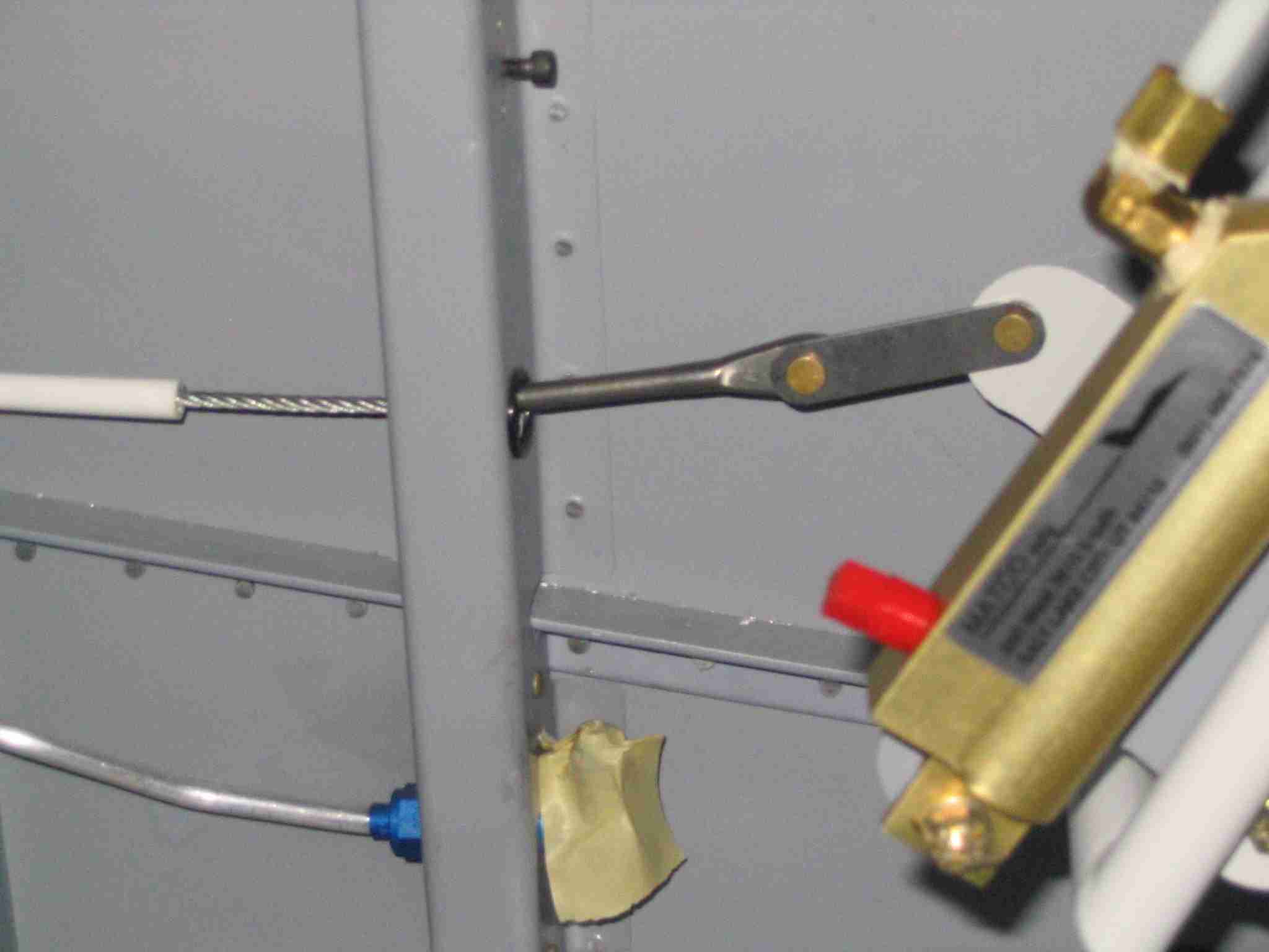
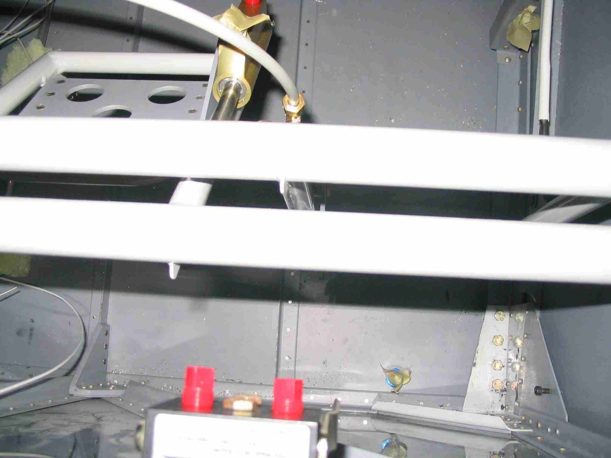
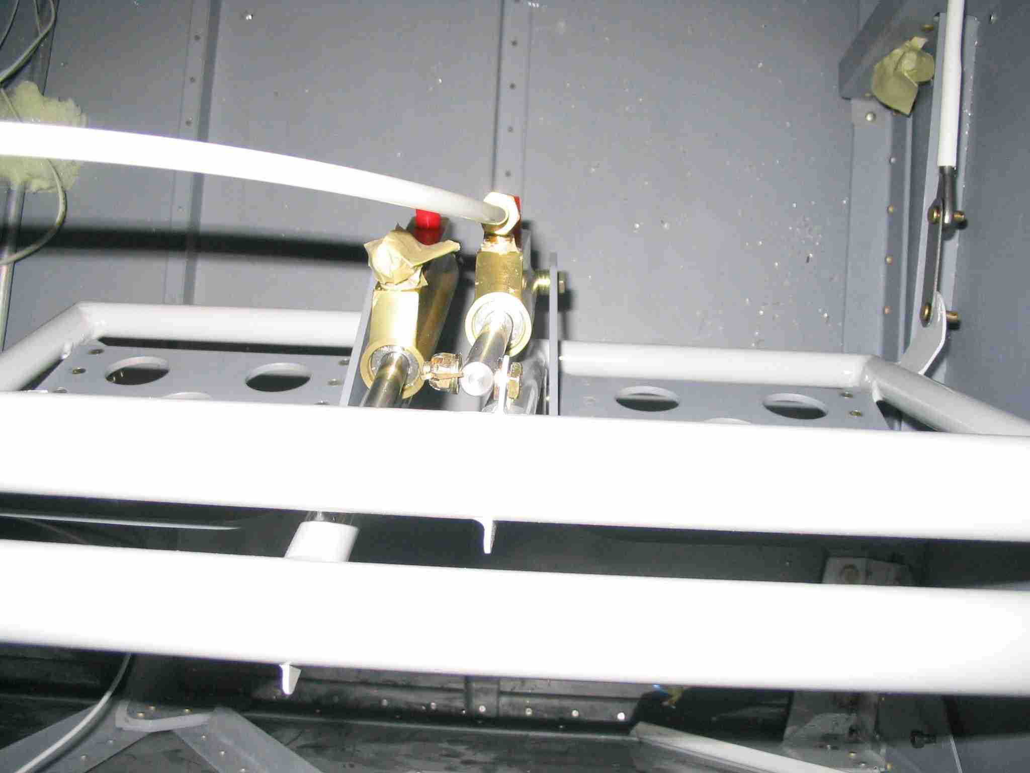
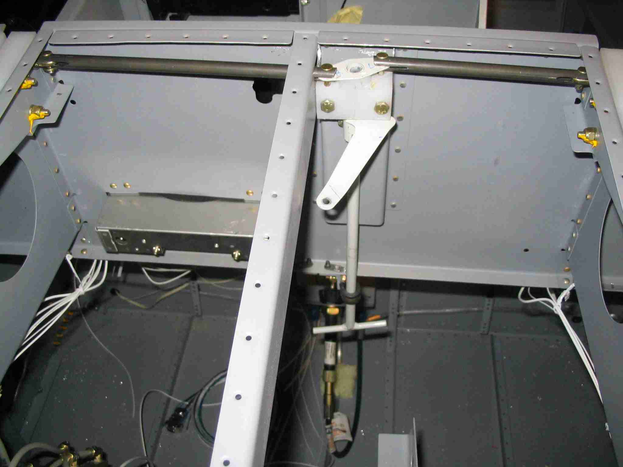
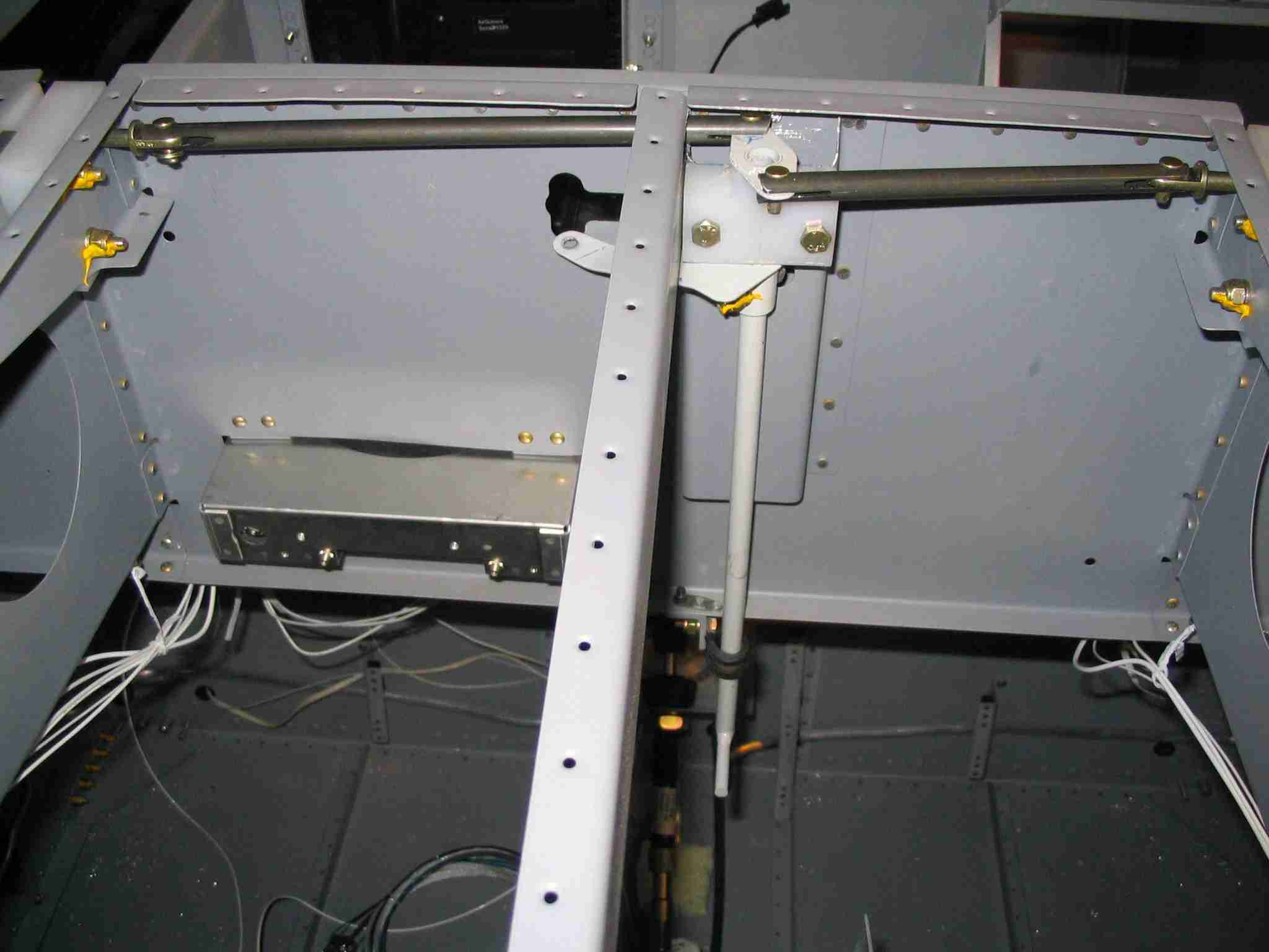
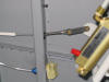
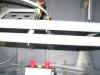
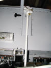
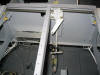
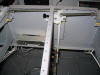
  F
Here are some pictures of the parking brake routing. The
parking brake handle is in the left side of the instrument
panel, above the longeron. In the first picture it can
be identified by the the brass tube protruding horizontally
from right to left and transitions to a silver cable.
The second picture illustrates the aluminum angle and adel
clamp used to hold the cable sheathing in place above the
parking parking brake. The parking bake is the black box
with the red caps protruding from it. All that is left
is to connect the cable to the brake and run the remaining
brake lines. The cap screw that secures the left side of
the aluminum angle will also support the fuel vent line.
(4/23/06) F
Here are some pictures of the parking brake routing. The
parking brake handle is in the left side of the instrument
panel, above the longeron. In the first picture it can
be identified by the the brass tube protruding horizontally
from right to left and transitions to a silver cable.
The second picture illustrates the aluminum angle and adel
clamp used to hold the cable sheathing in place above the
parking parking brake. The parking bake is the black box
with the red caps protruding from it. All that is left
is to connect the cable to the brake and run the remaining
brake lines. The cap screw that secures the left side of
the aluminum angle will also support the fuel vent line.
(4/23/06) |
| |
|
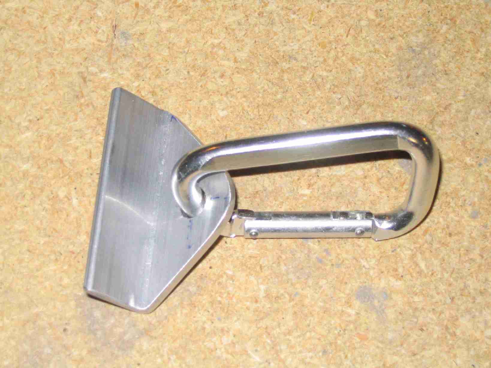
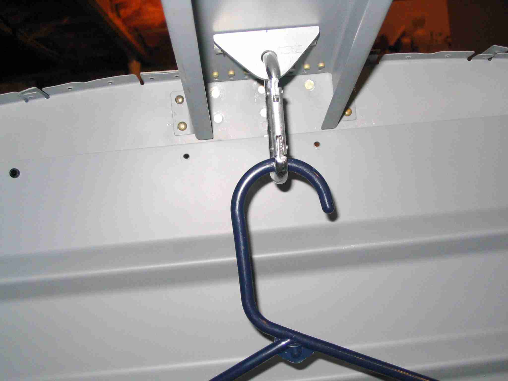
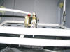
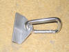  E
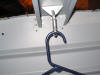
Sometimes you just have to work on your "Honey Do" list when
building an airplane. My list included adding a cloths
hanger for my wife. Let's face it, we hope to use the -9
to take some trips and it would be nice if our clothes made it
without looking like they were left in the dryer for a week.
When finished I simply riveted it to the support above the
baggage compartment. Remember, this plane will have the
tip-up canopy, sliders do not have this support. The
aluminum angle was some scrap I had laying around and the
carabineer was found at the local hardware store for $1.00.
Total weight gain was a few ounces.
(4/25/06) E
Sometimes you just have to work on your "Honey Do" list when
building an airplane. My list included adding a cloths
hanger for my wife. Let's face it, we hope to use the -9
to take some trips and it would be nice if our clothes made it
without looking like they were left in the dryer for a week.
When finished I simply riveted it to the support above the
baggage compartment. Remember, this plane will have the
tip-up canopy, sliders do not have this support. The
aluminum angle was some scrap I had laying around and the
carabineer was found at the local hardware store for $1.00.
Total weight gain was a few ounces.
(4/25/06) |
| |
|
  F
It took about an hour to cut the second pull tube for the
canopy release. This pictures show the completed release
installed in both the open and closed position. Note the
adel clamp at the bottom of the "T" handle to keep it from
moving.
(4/25/06) F
It took about an hour to cut the second pull tube for the
canopy release. This pictures show the completed release
installed in both the open and closed position. Note the
adel clamp at the bottom of the "T" handle to keep it from
moving.
(4/25/06) |
| |
|
E
Page
F |