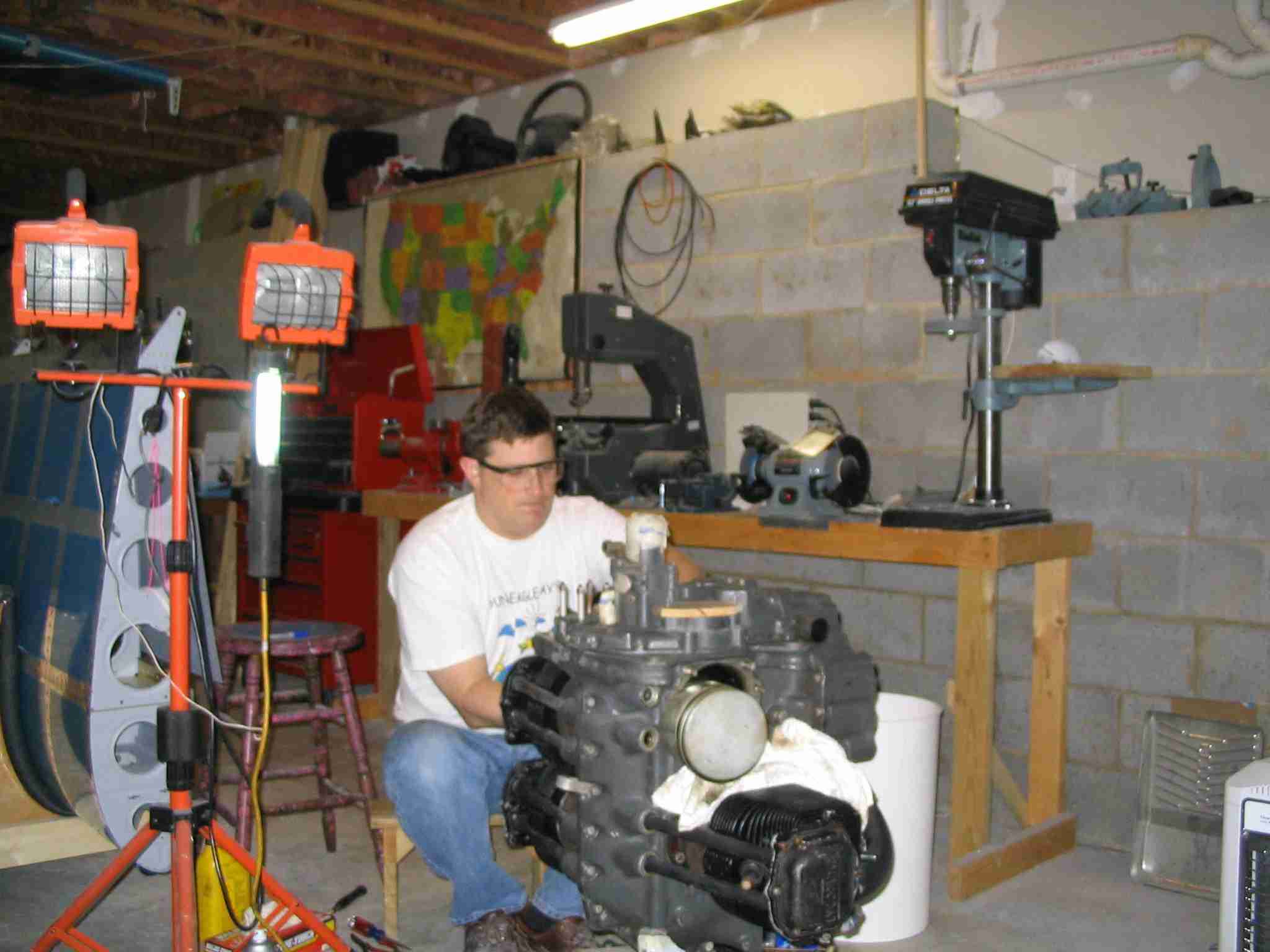
Building in the Basement and Moving to the Airport
E-mail:
bill (at) repucci (dot) com
|
Engine Rebuild and Installation aka Firewall Forward Caution - Man running (with) power tools Next Page F
| ||||||||||||||||||||||||
 E
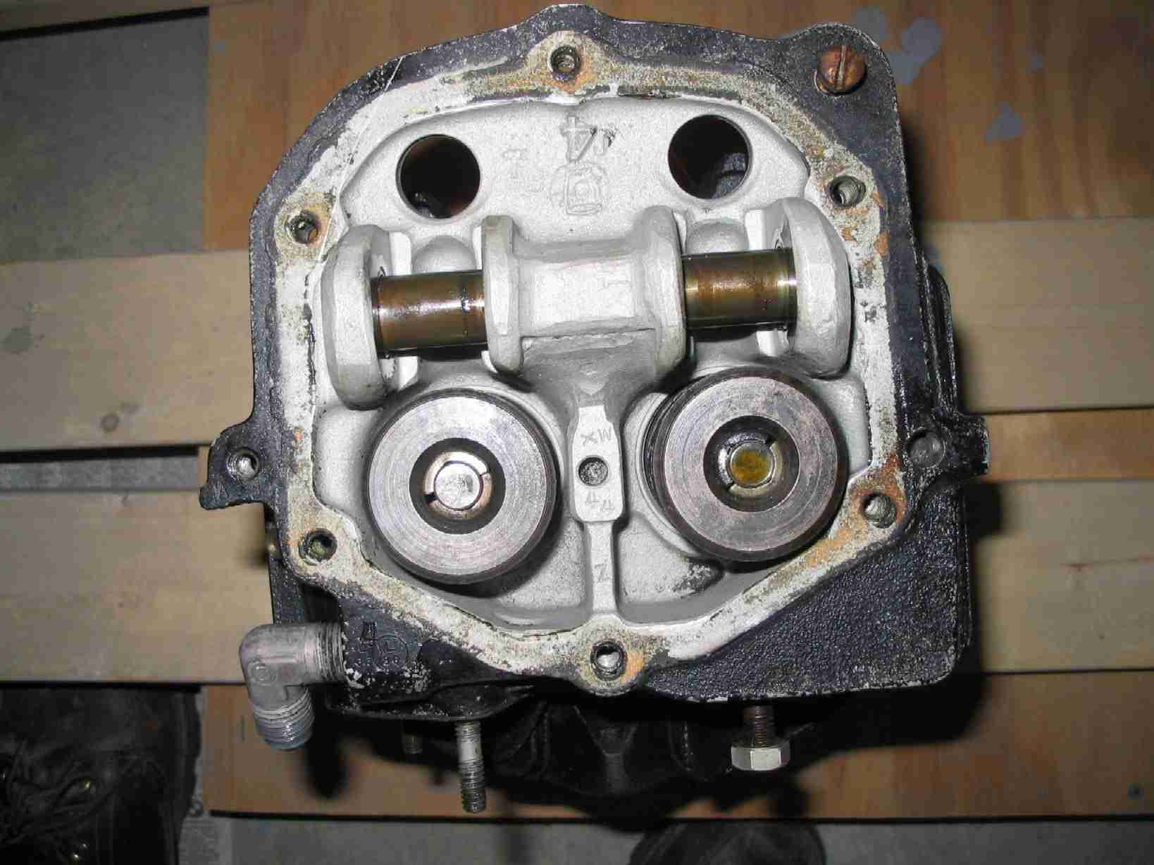
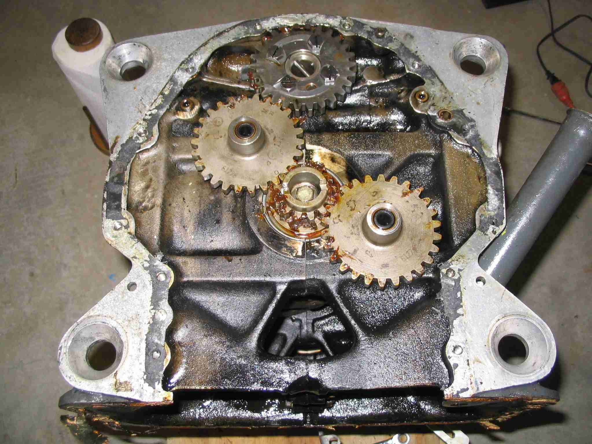
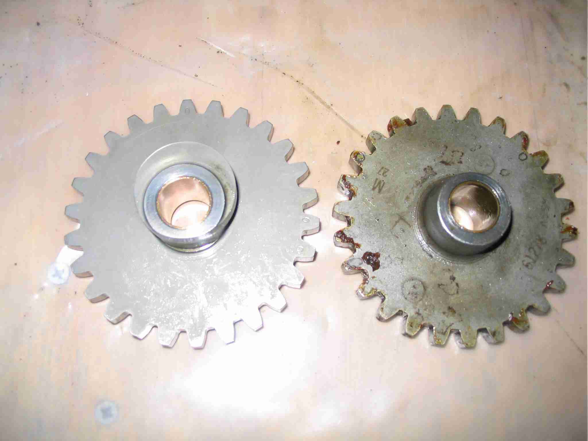
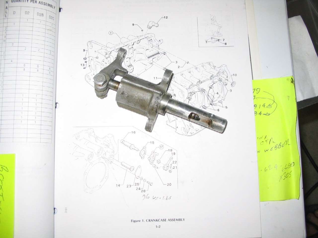
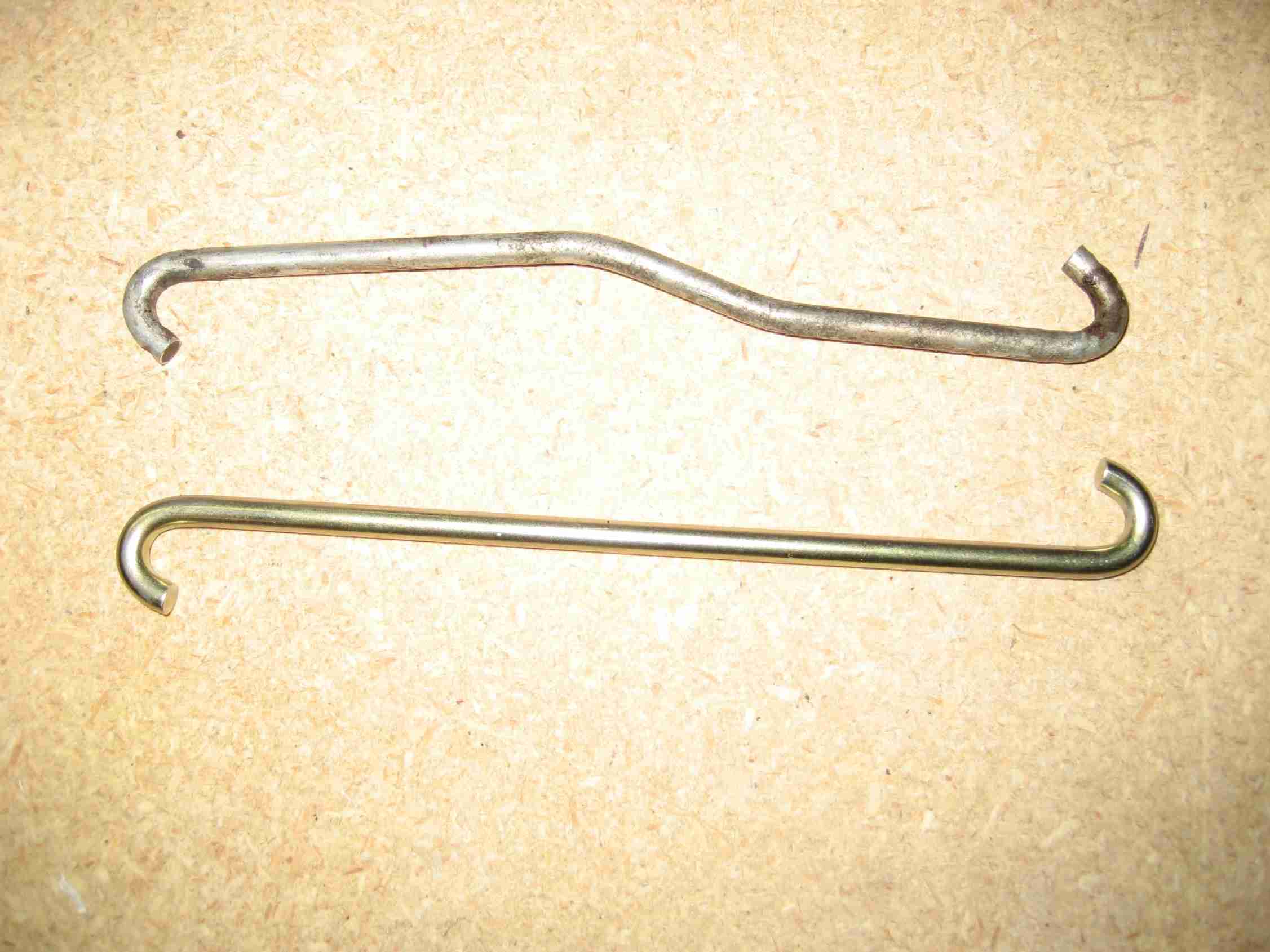
The idler gear with the cam to drive the fuel pump push rod arrived on
Thursday and slid right into place. Here it is on the left, next to
the gear it is replacing. The old gear is covered in 50 year old
grease and is in very good shape. Time to eBay that sucker.
(1/20/05) E
The idler gear with the cam to drive the fuel pump push rod arrived on
Thursday and slid right into place. Here it is on the left, next to
the gear it is replacing. The old gear is covered in 50 year old
grease and is in very good shape. Time to eBay that sucker.
(1/20/05) |
|
|
|
|
|
|
|
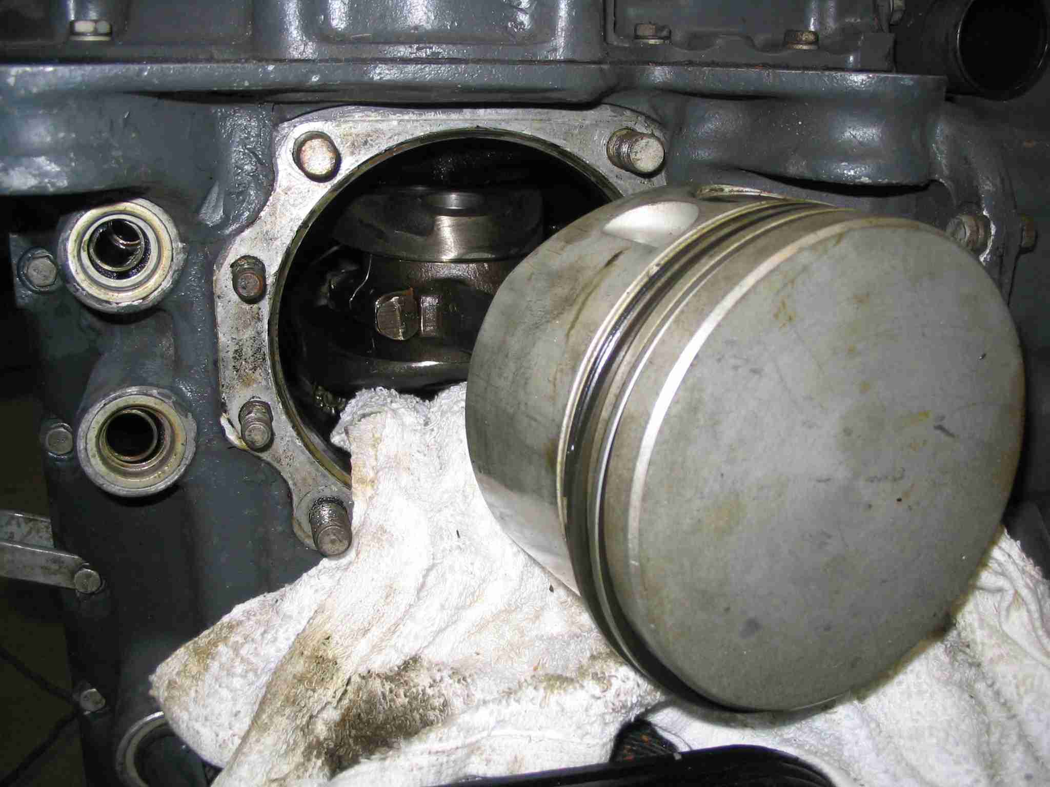
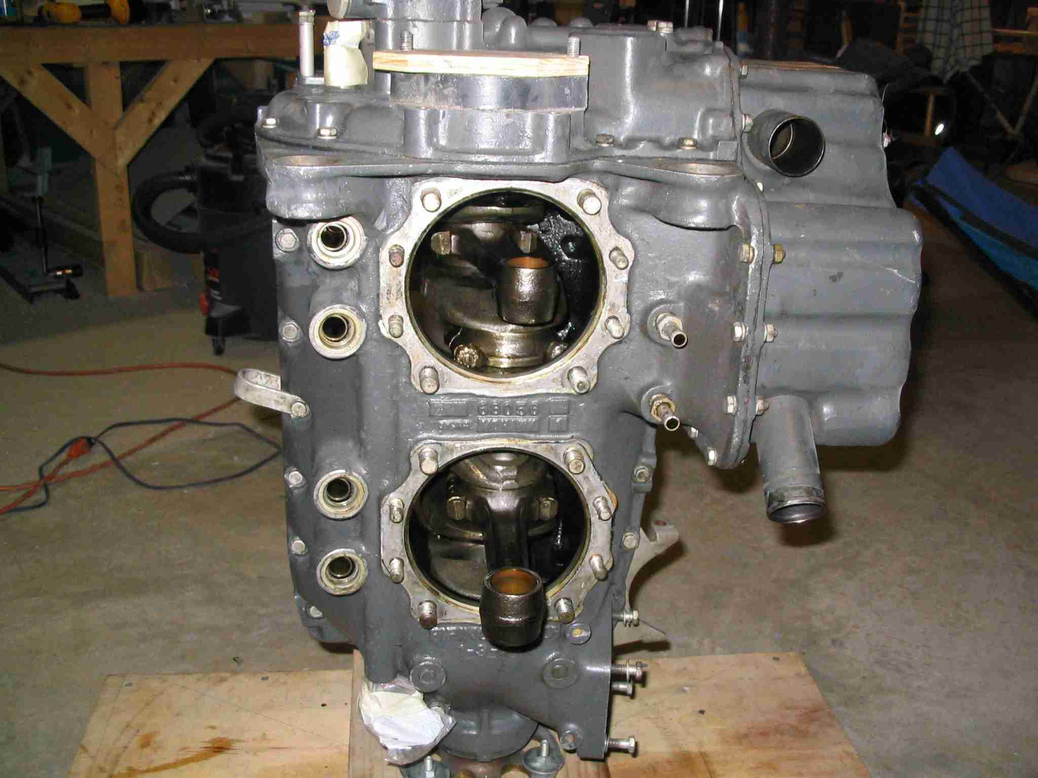
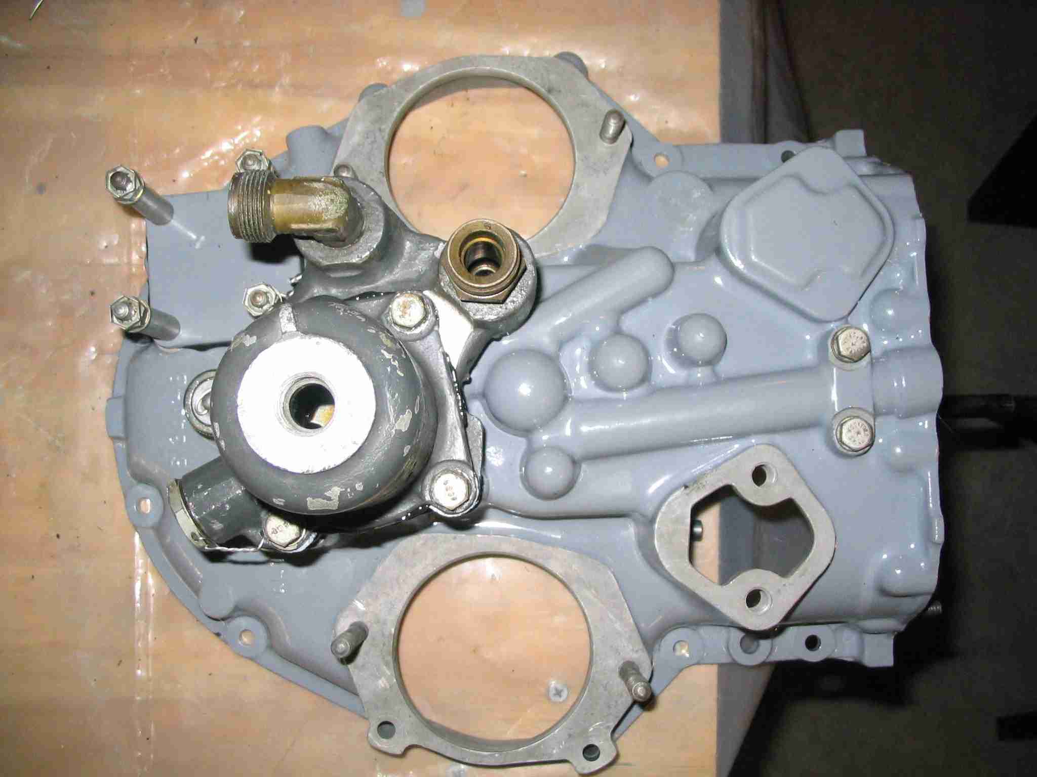
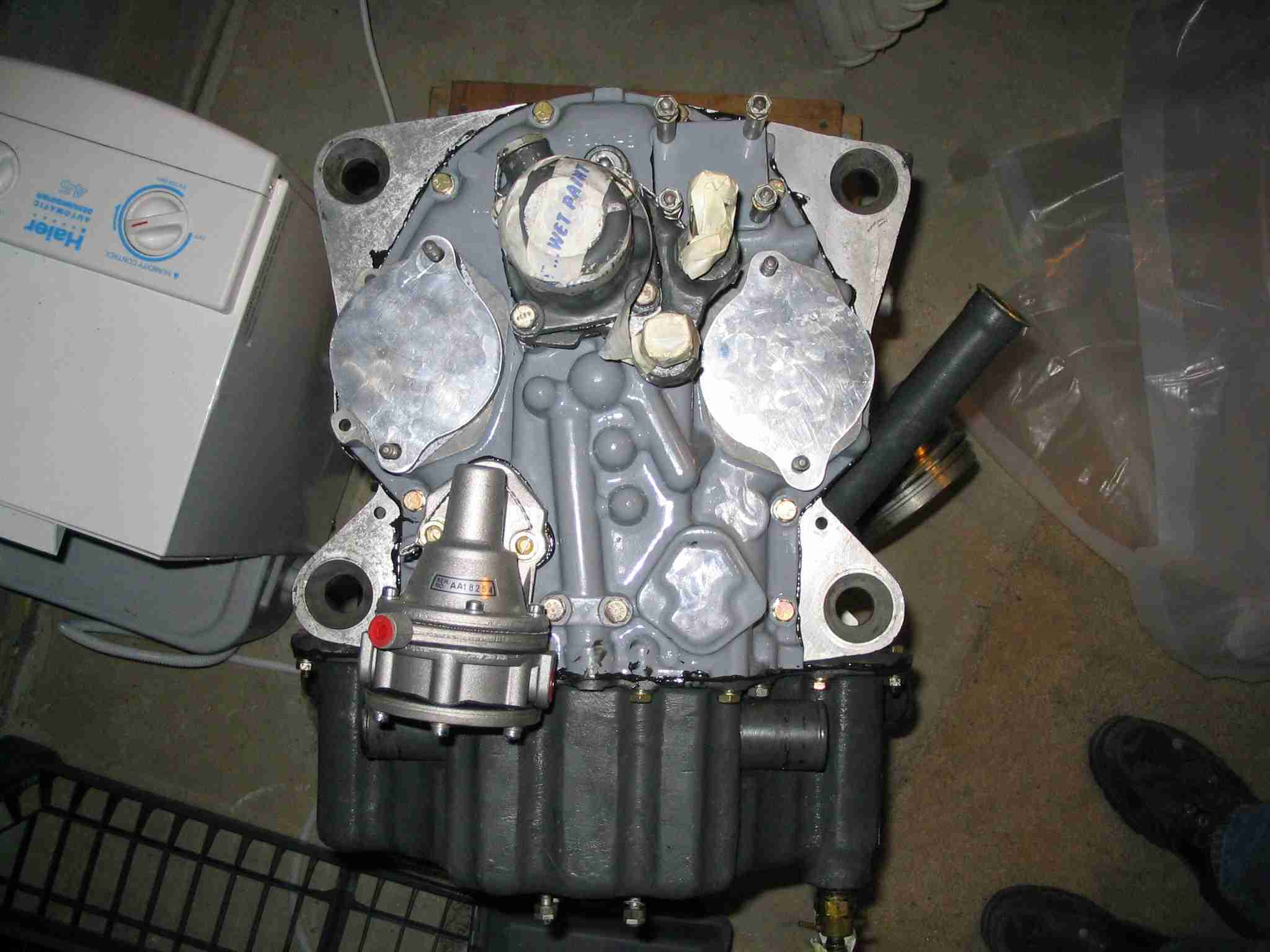
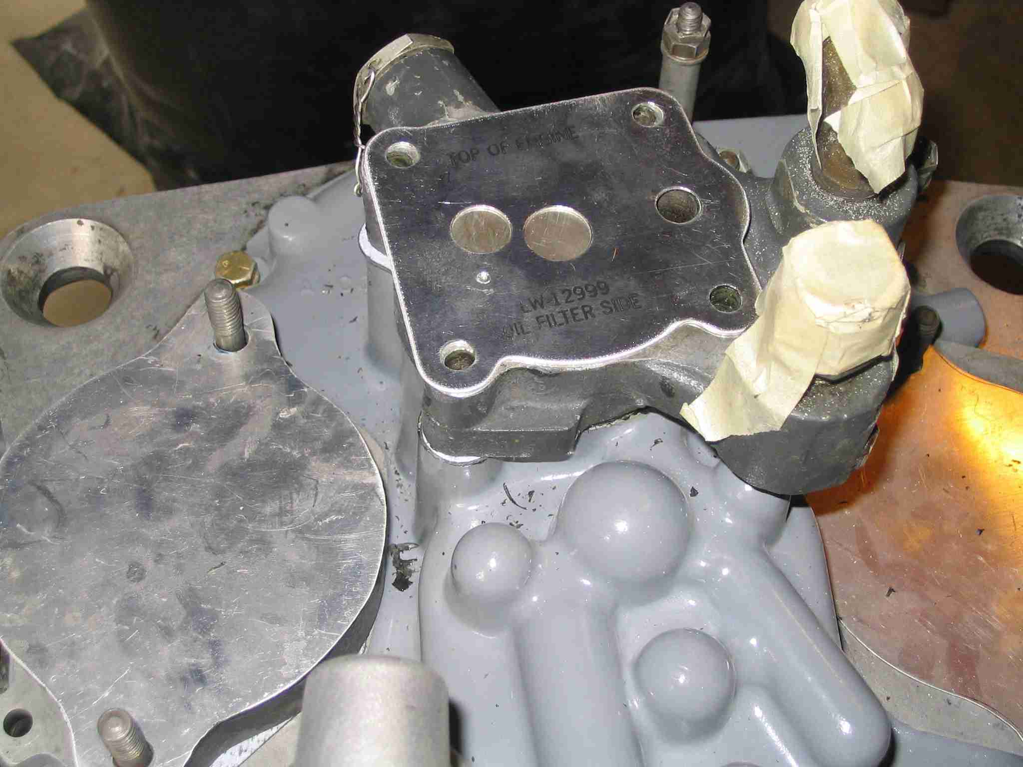
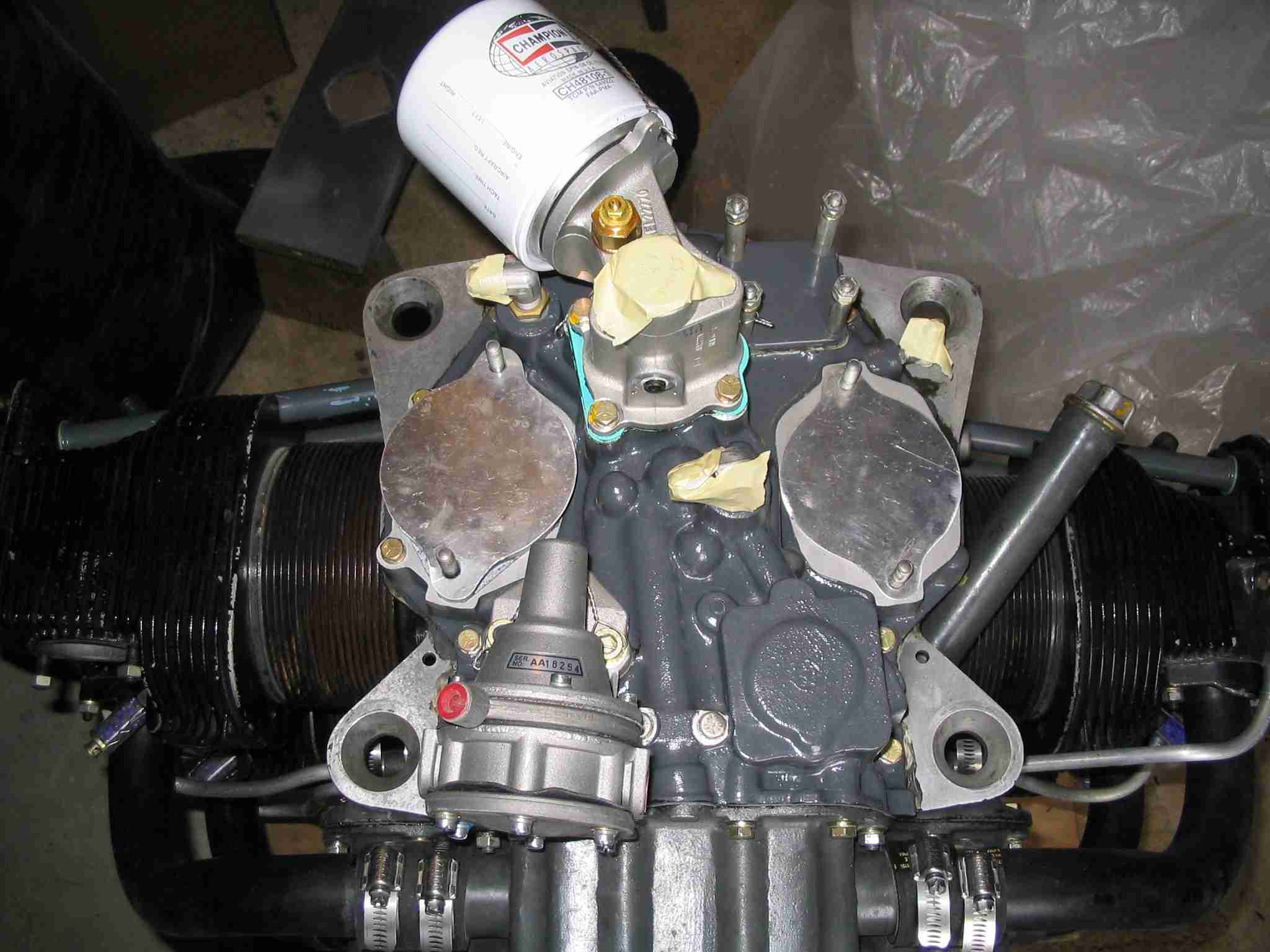
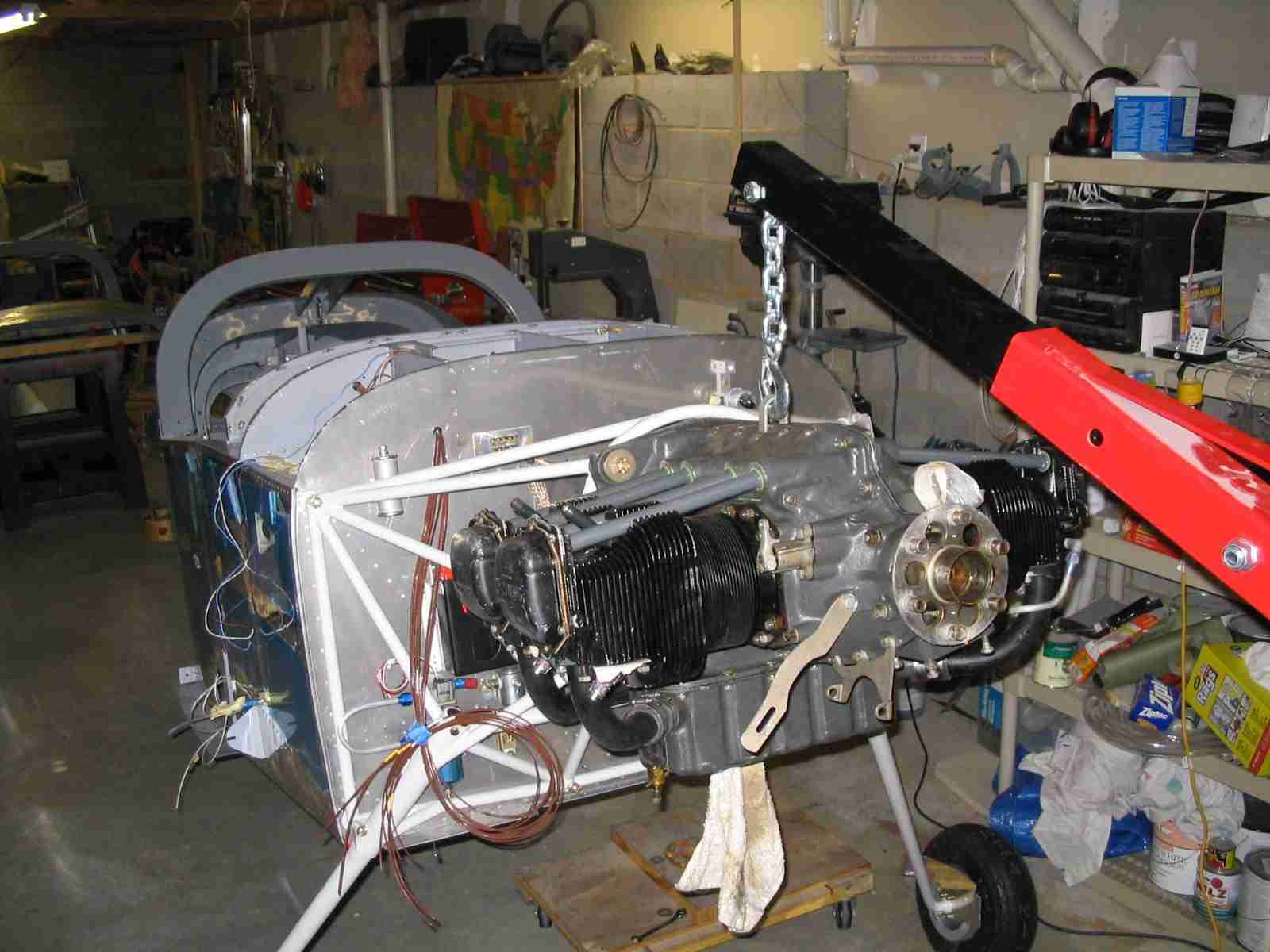
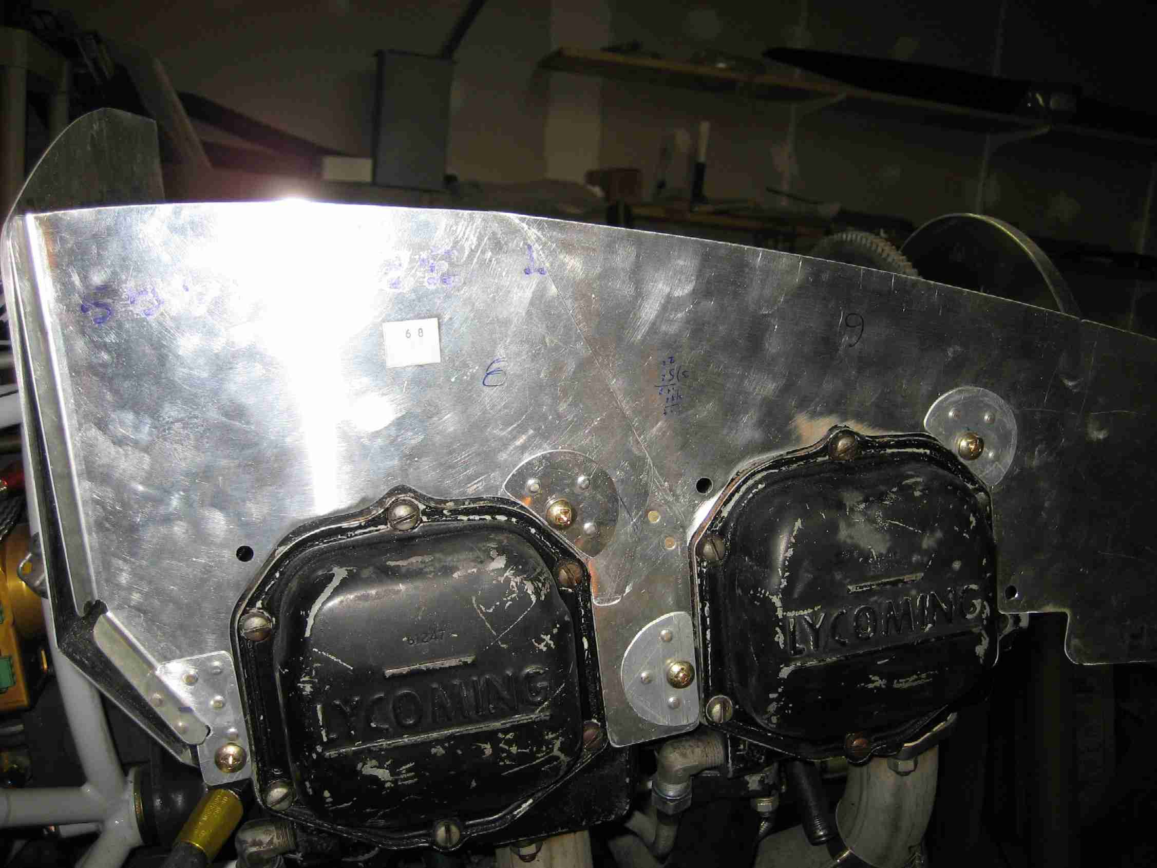
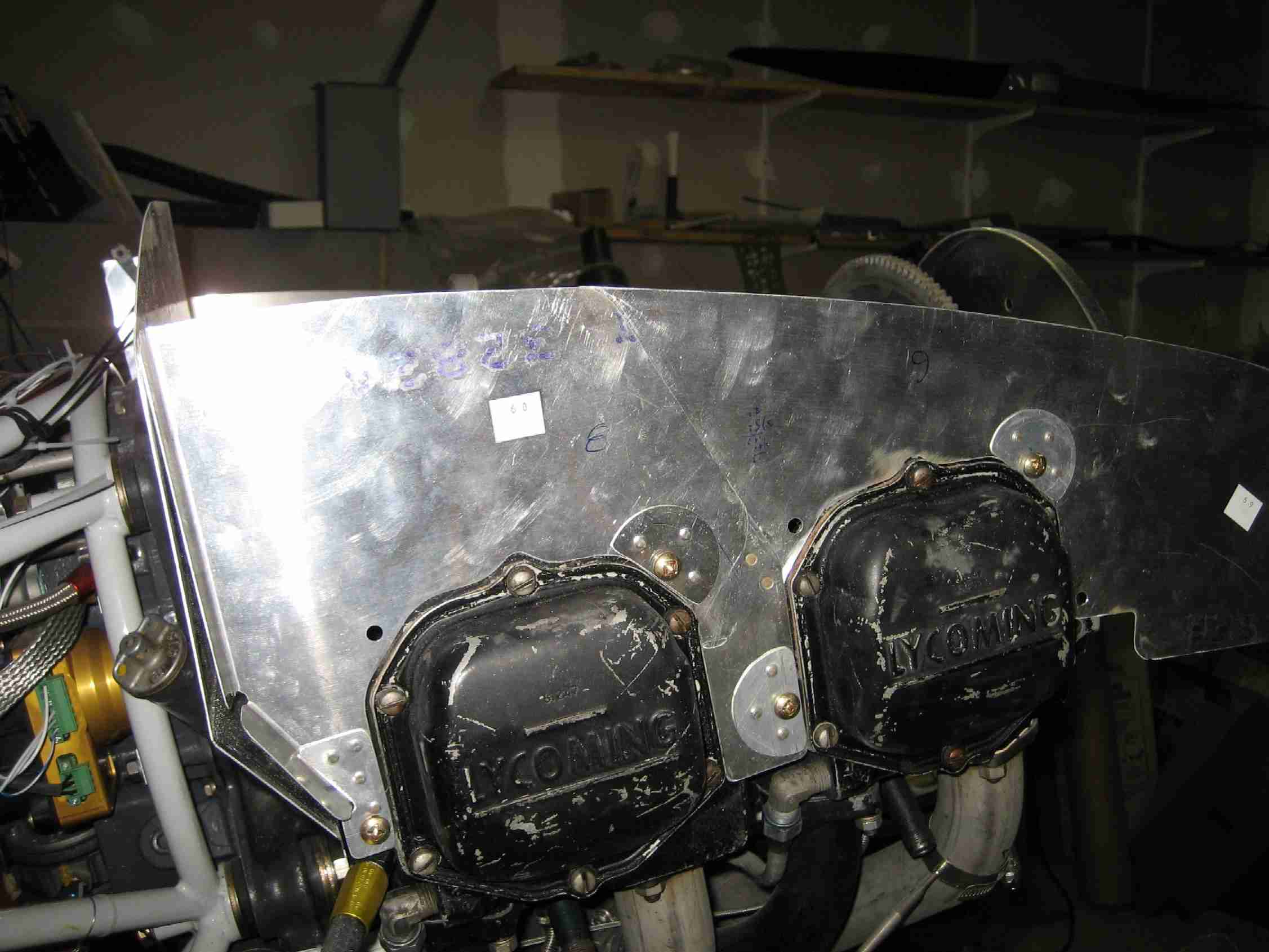
S Last week a friend came over who is also an IA just to check out the project. He thought I was doing a good job on the metal work but didn't like the amount of gasket sealant I used on the accessory case and oil sump. A quick call to Aircraft Spruce had two new gaskets on the way (Less than $15). Off came the case and oil sump and on went the new gaskets with much less sealant. Lesson learned. It took about three hours to accomplish that task. Dehydration plugs where installed and the engine was pushed back into the corner next to the dehumidifier for safe keeping. Next up will be to replace the oil screen with a filter. I will mostly likely go with the Mattituck Oil Filter Adapter. This may wait until I'm closer to hanging the engine. (4/7/05) |
|
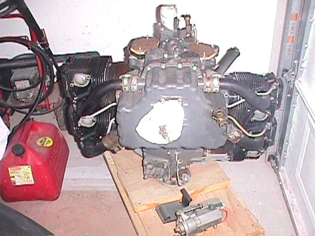
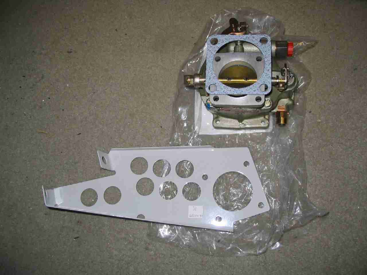
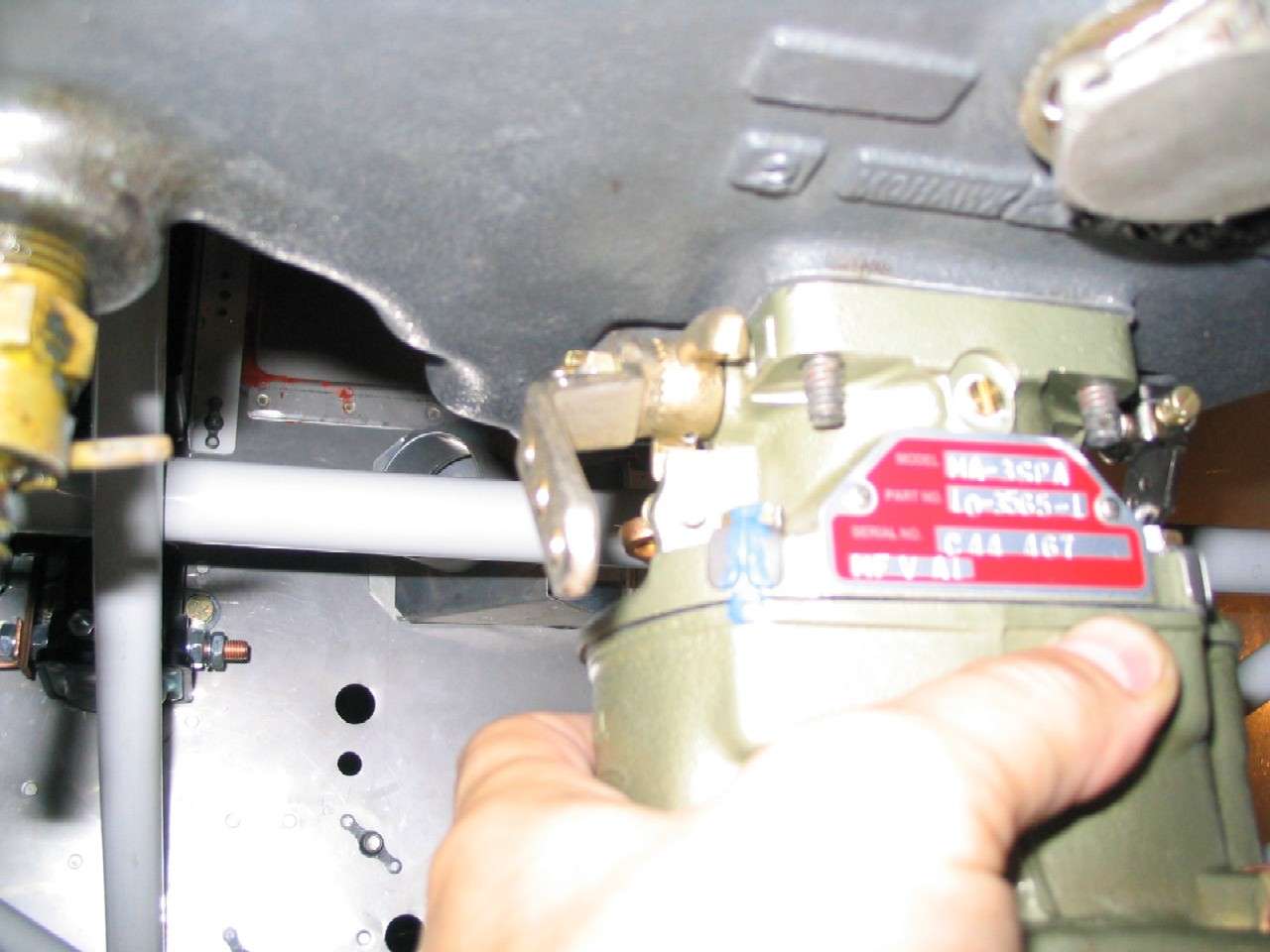
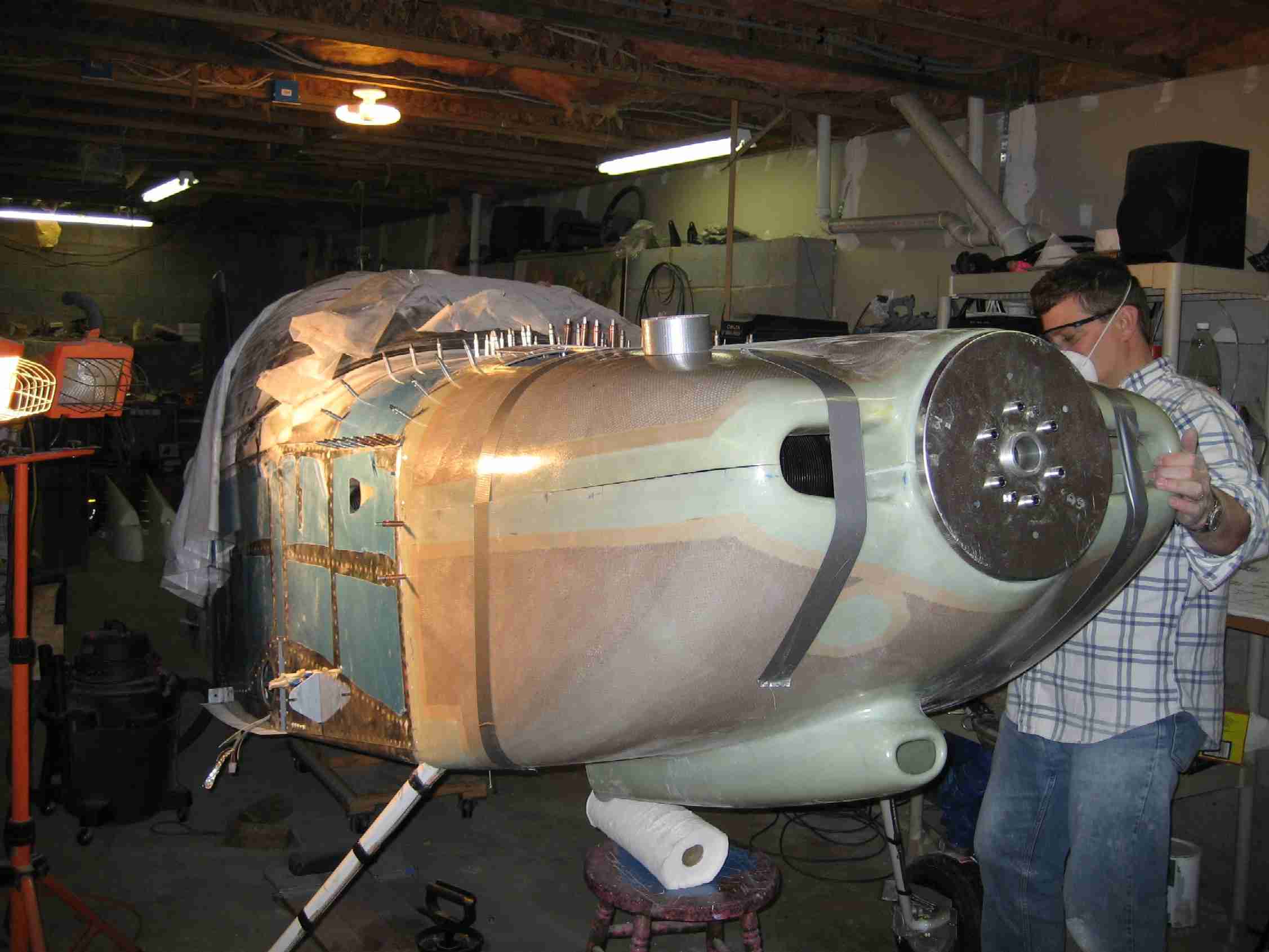
j The engine has been pickled and pushed off into a corner of my basement/shop next to the dehumidifier while I work on finishing up the fuselage. In the meantime I've been looking for additional items to complete my O-290-D2. These items include a carburetor, fuel filter, and magnetos. After many false starts trying to locate a carburetor I finally hit on the solution after watching a news report about the gulf cost hurricane damage; there on the TV were some guys riding through downtown New Orleans on air boats and wouldn't you know it, airboats are powered by airplane engines. A quick Google search of "Lycoming O-290 airboat Florida" turned up Outlaw Aircraft Engines. They had just the carburetor I needed for a reasonable price. Notice that I didn't say a good price. The strange thing is the name of the suppler is the same as the name of the guy who I bought the engine from. The carb should arrive in a few days and once it gets here I will rebuild it using all new parts. (10/11/05) |
|
|
|
|
|
|
|
|
|
|
|
|
|
|
|
|
|
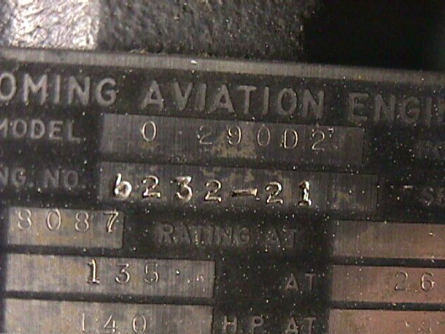
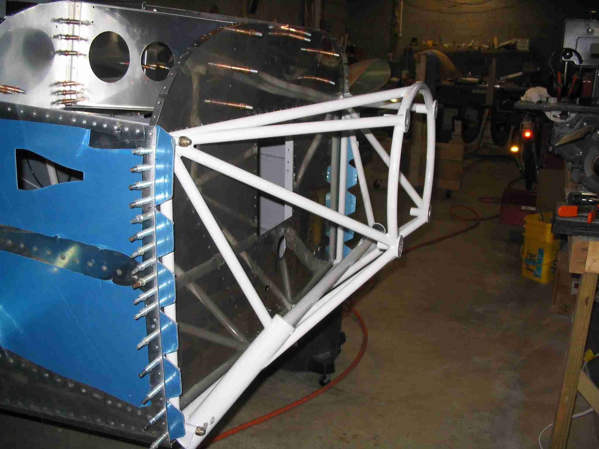
O-290 Specific Issues As stated above, this section will detail my quest to mount an O-290-D2 engine on my RV-9. Although Vans has approved this engine for the RV-9, they have not installed one. One of their tech's went as far as suggesting I not use this engine and mentioned that none of Van's aircraft have one installed so they would be hard pressed to help me with the installation. Heck, if I where scratch building I couldn't even call Vans for help, so I can't get upset with them for being so cheep as to buy this engine and not a new one like most other RV builders. There are a few O-290 powered RV-9's flying but the owners have been reluctant to help me for whatever reason. I suspect it is because they would rather fly than take their cowling off and shoot pictures and I can't say as I fault them. One builder/flier told me to just buy the O-320 FWF kit and trim down the exhaust system. That sounded like good advice and it was but I'm finding subtle differences between the O-320 and the O-290 and it is those differences I hope to document here. The long and short of it is, your mileage may very should you follow this path.
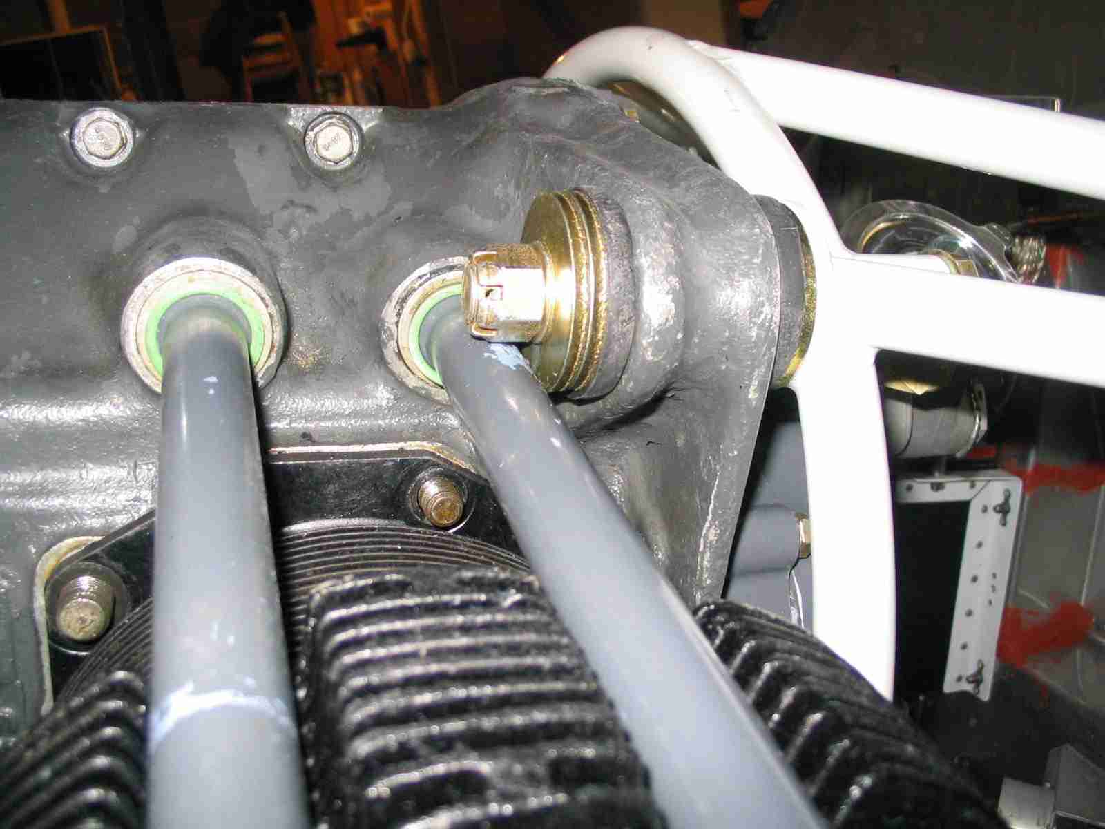
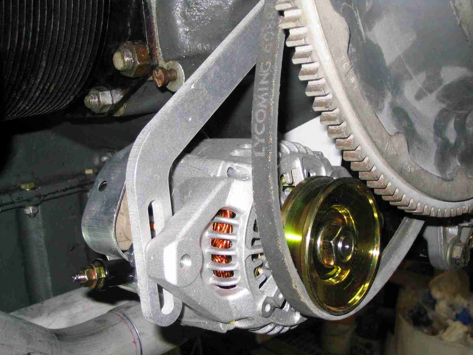
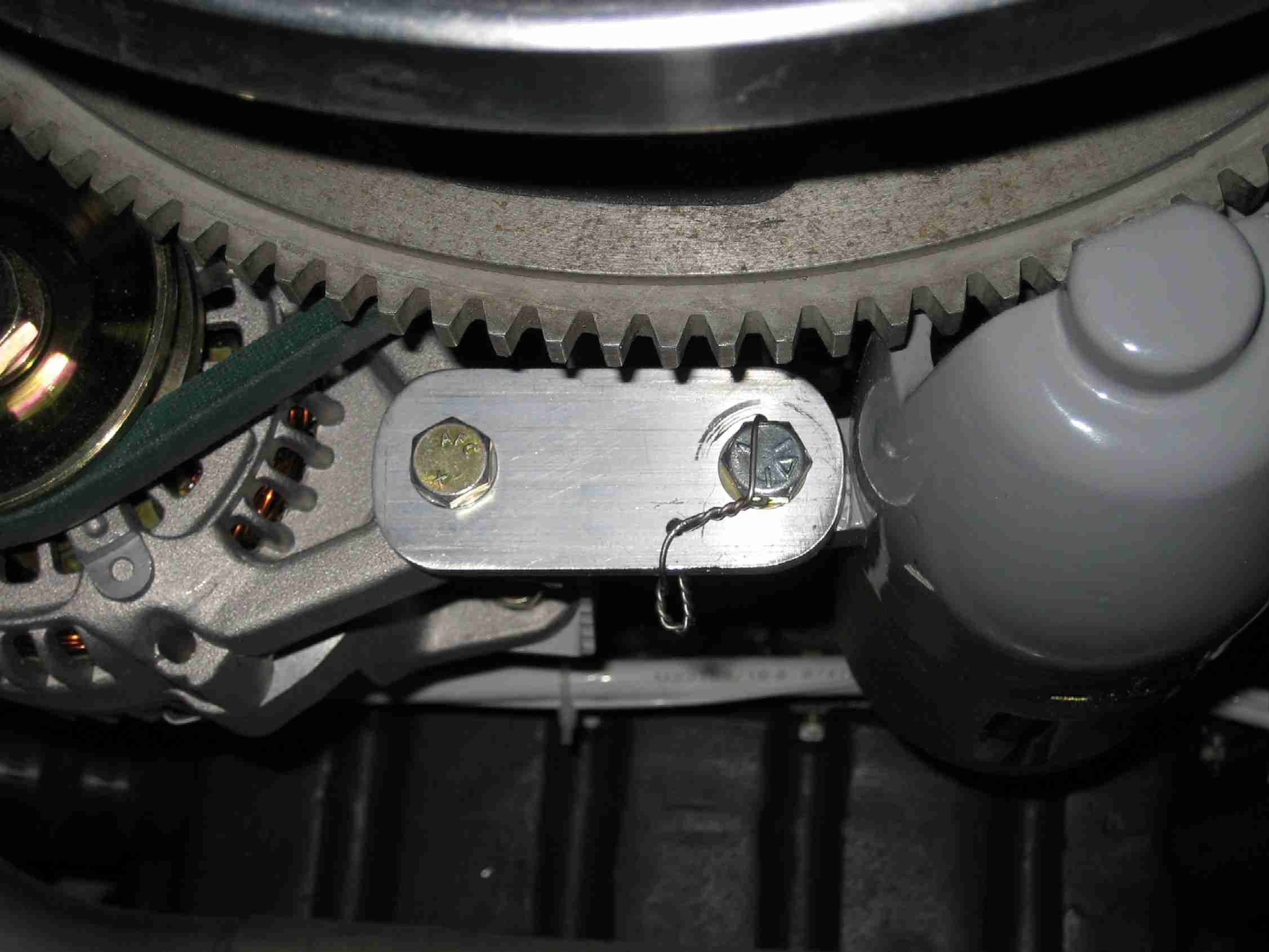
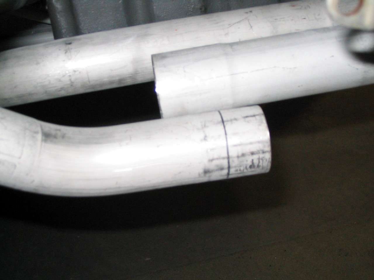
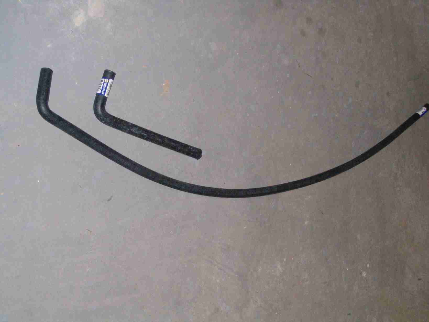
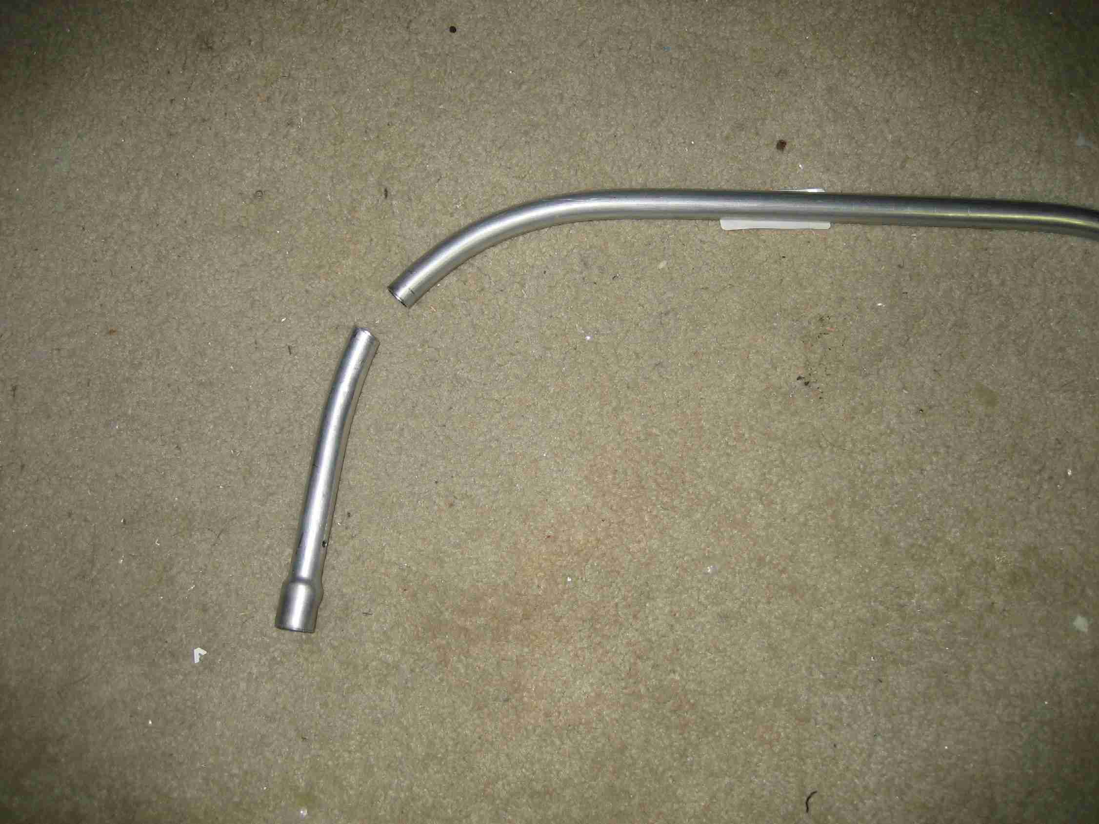
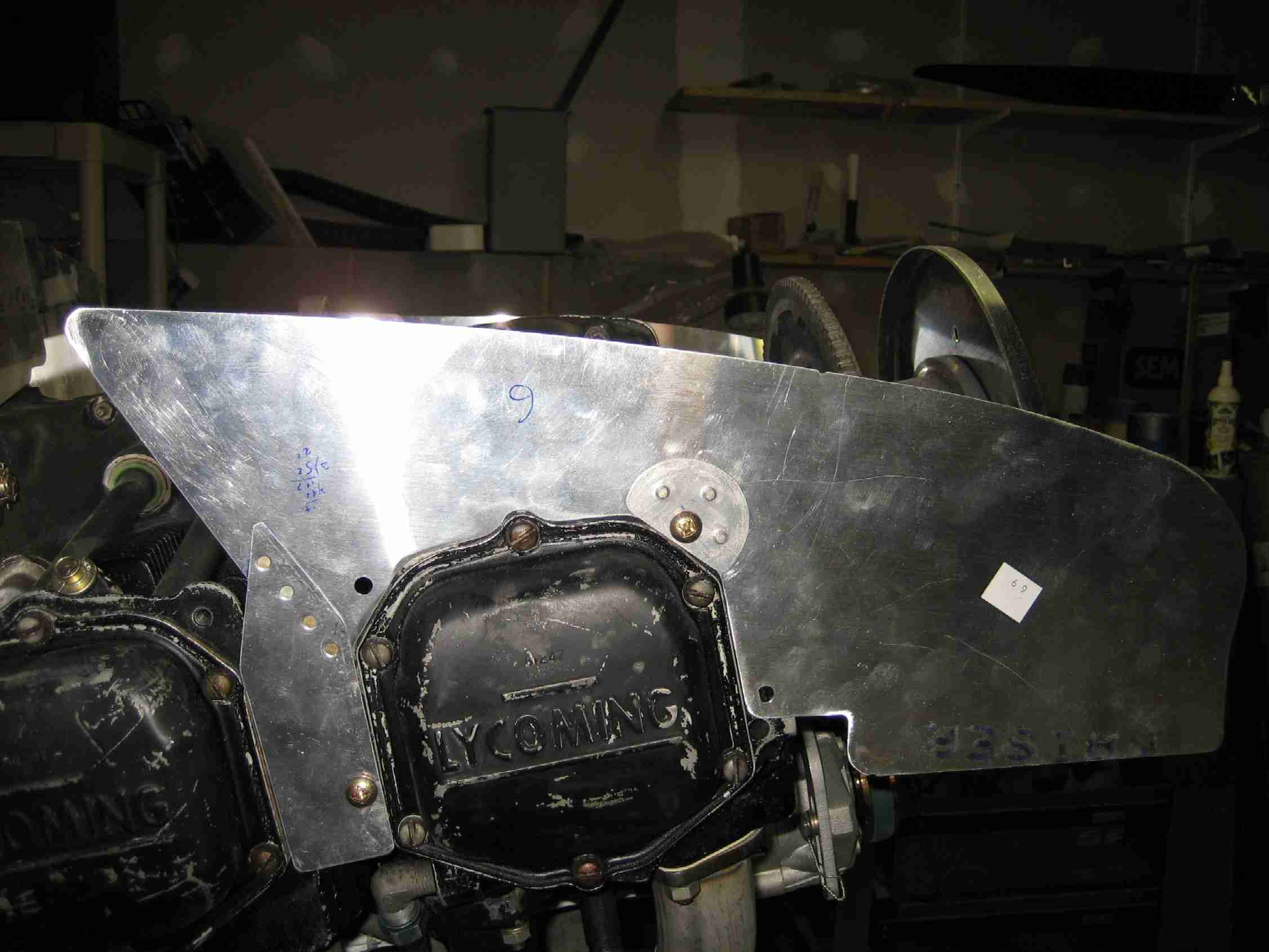
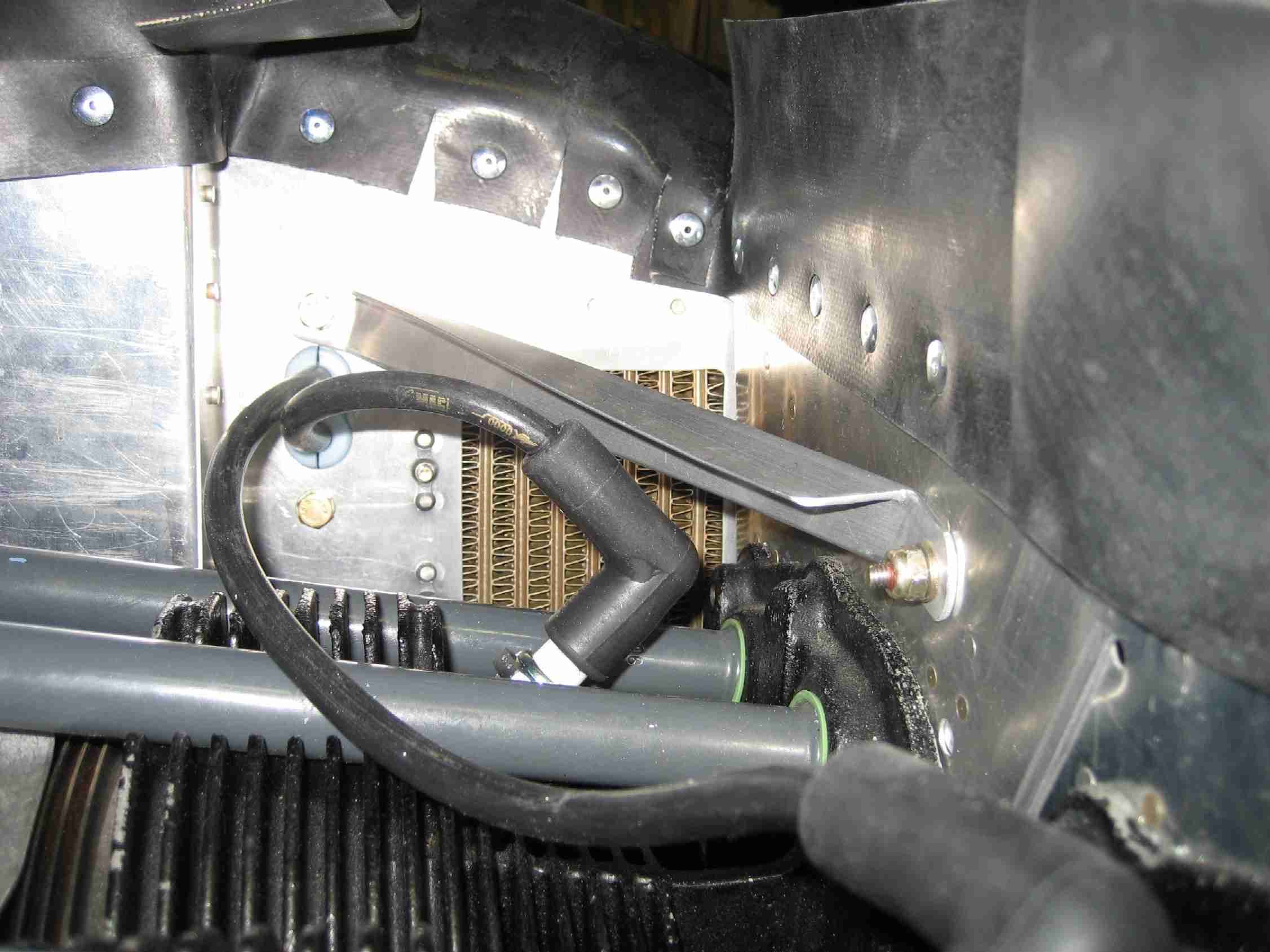
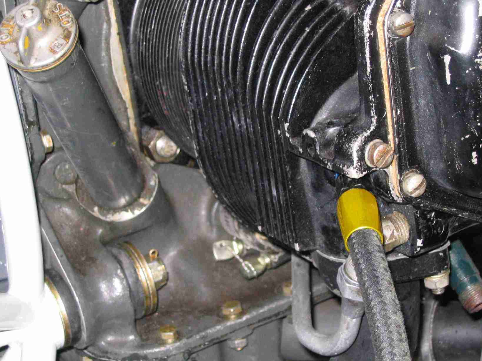
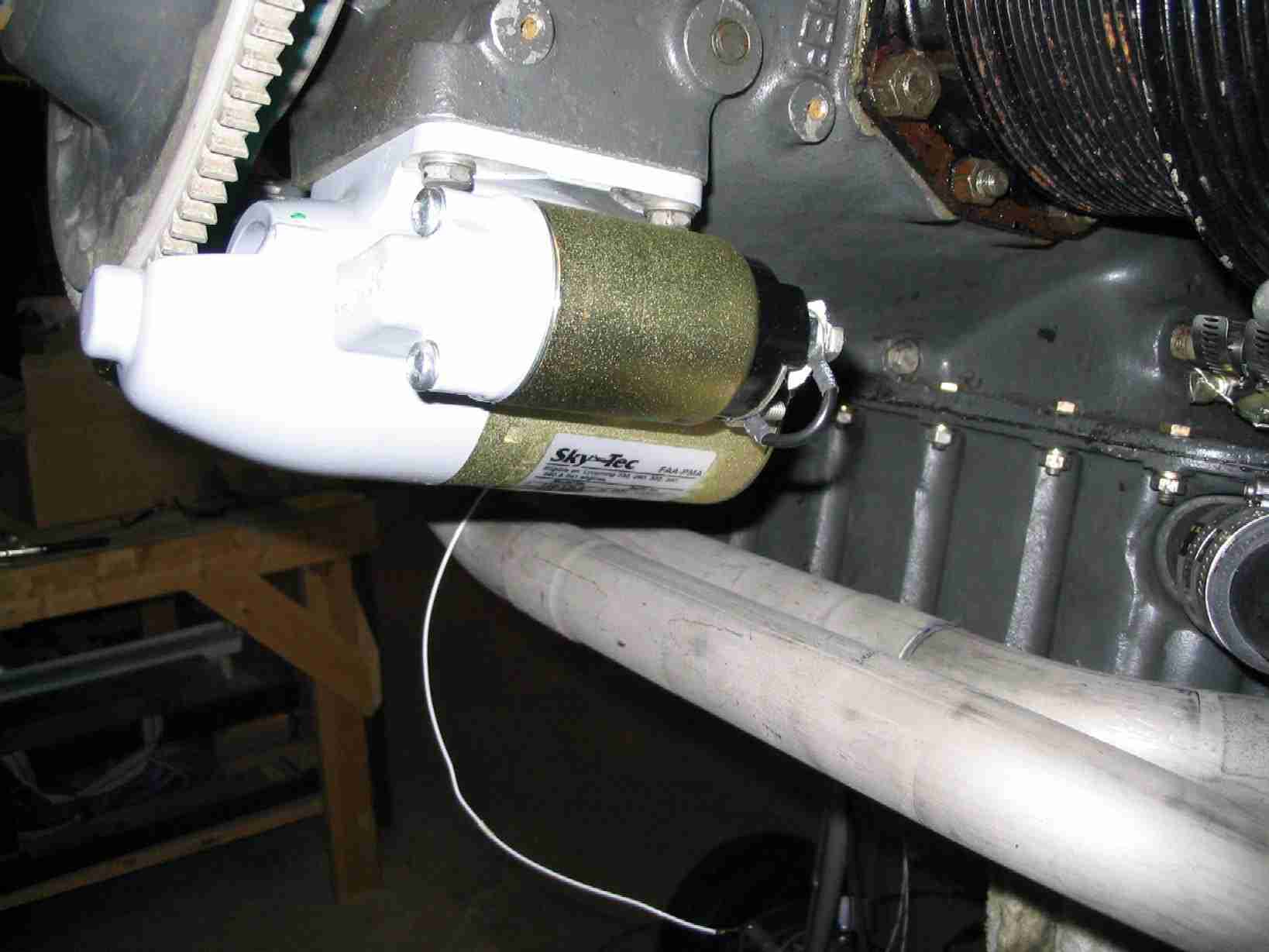
After a few trips to NAPA I finally found the right length alternator belt. When I bought the engine it came with the belt in the picture above, and although it was an Lycoming part, it was old, dried out, and the wrong size for this application. I finally cut the belt, held it in place, and marked it at the proper length. The local NAPA dealer used this to figure out the correct belt length. It only took me a few trips to think about cutting this old belt. Big DUH on my part. Anyway, after talking to the NAPA guy about how the belt was going to be used he suggested I buy a lawn mower (garden) belt as they should last longer. Sounded good to me so I now have a "Heavy Duty FHP Belt", NAPA part number 4L310W, 1/2" x 31" green belt. (Issue closed 10/14/06)
Update: The NAPA hose depicted above will not work. It turns that is a water hose and will eventually leak oil all over the place. In addition, after fitting the forward baffle I found the hole location was a real pain.
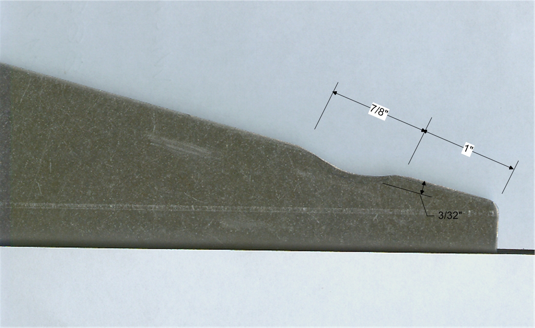
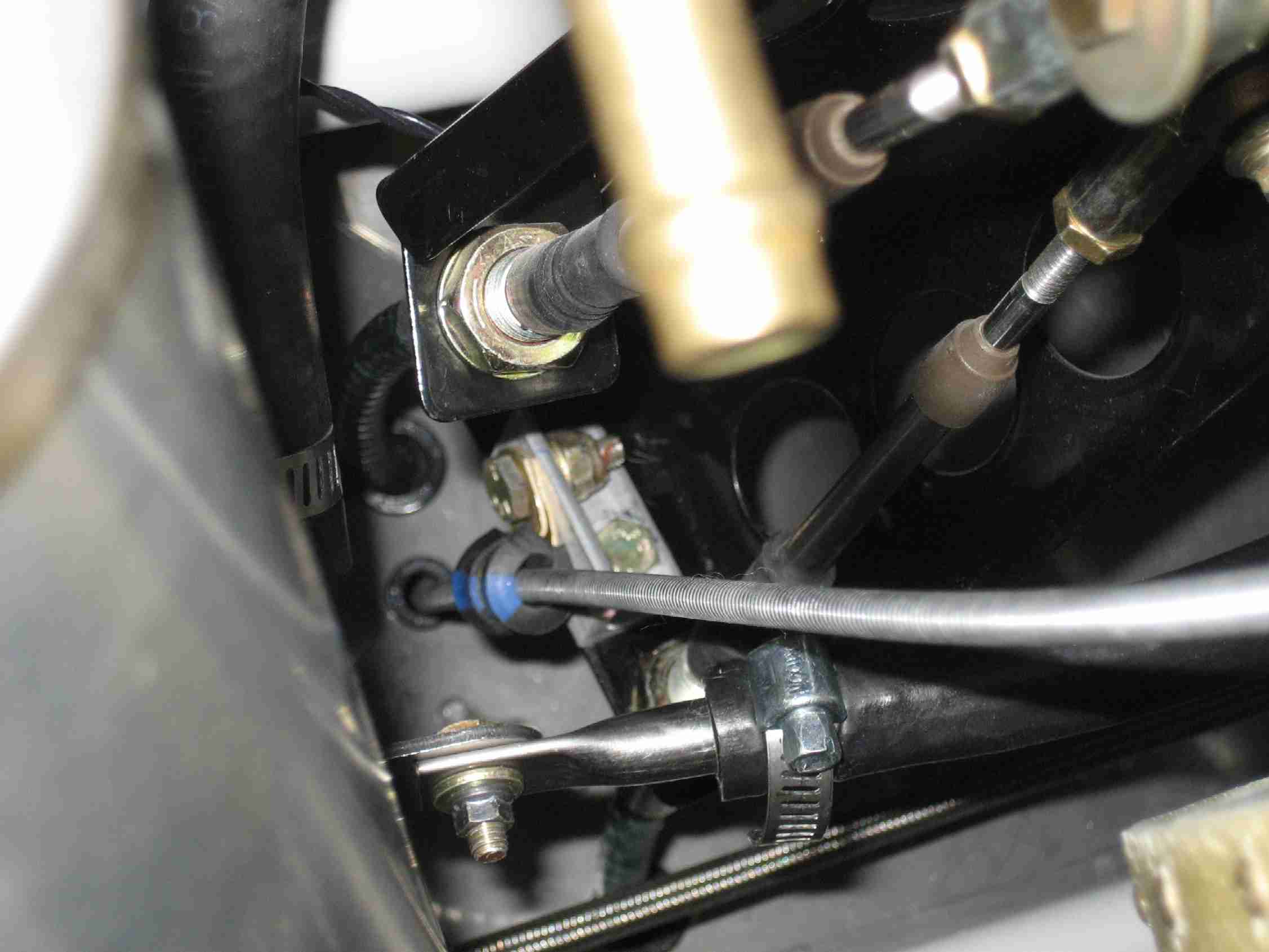
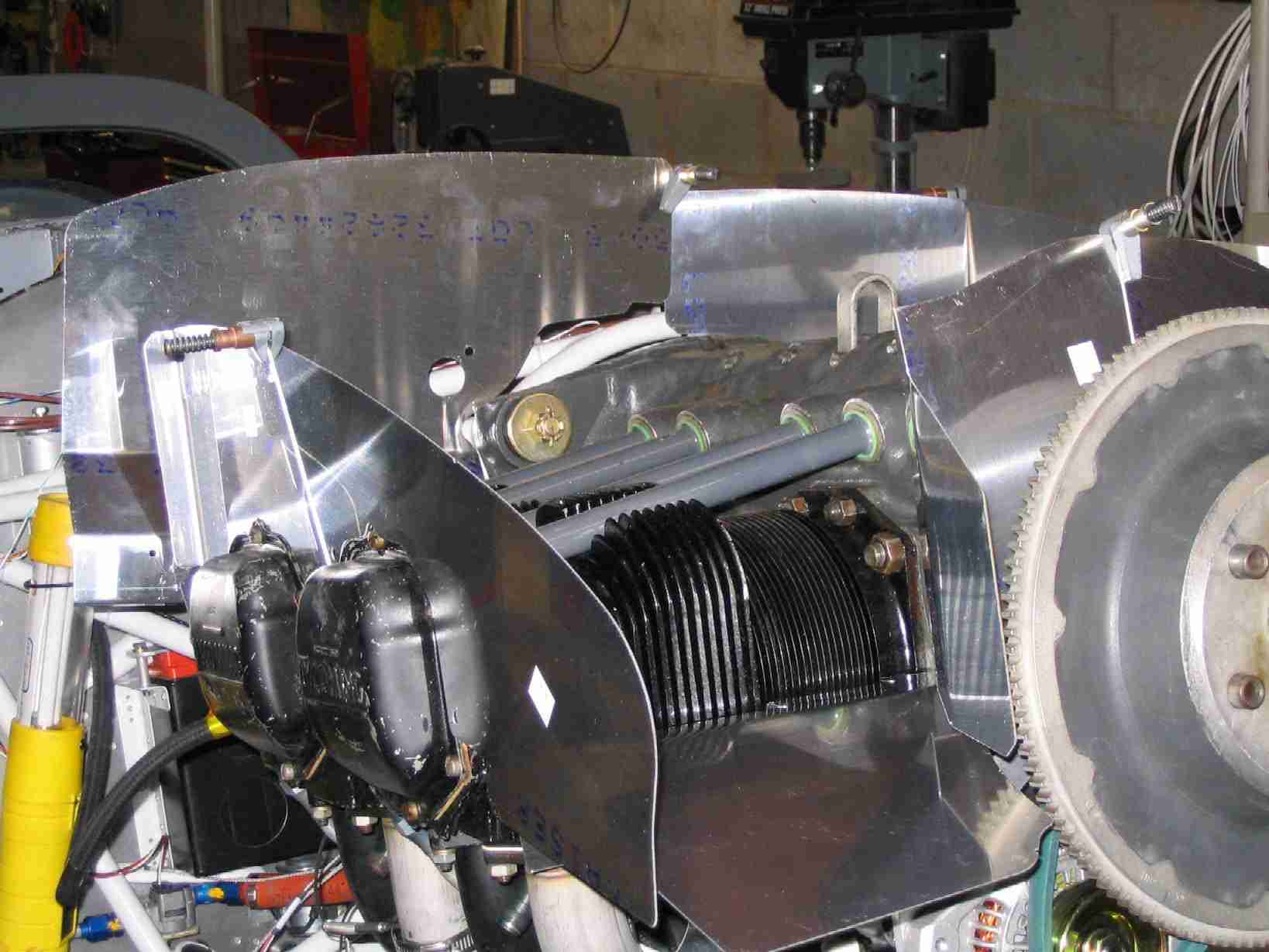
The standard Van's setup uses six LONG bolts to hold the forward prop spinner bulkhead, crush plate, prop, aft spinner bulkhead, spacer, and starter ring to the prop flange. Sabre's set up uses 12 shorter bolts. One short set holds the spacer and starter ring to the prop flange and another set of bolts hold the prop and two bulkheads to the spacer. Probably a better setup, more so since bolts to hold it together are available. (10/24/06)
|
|
|
 F
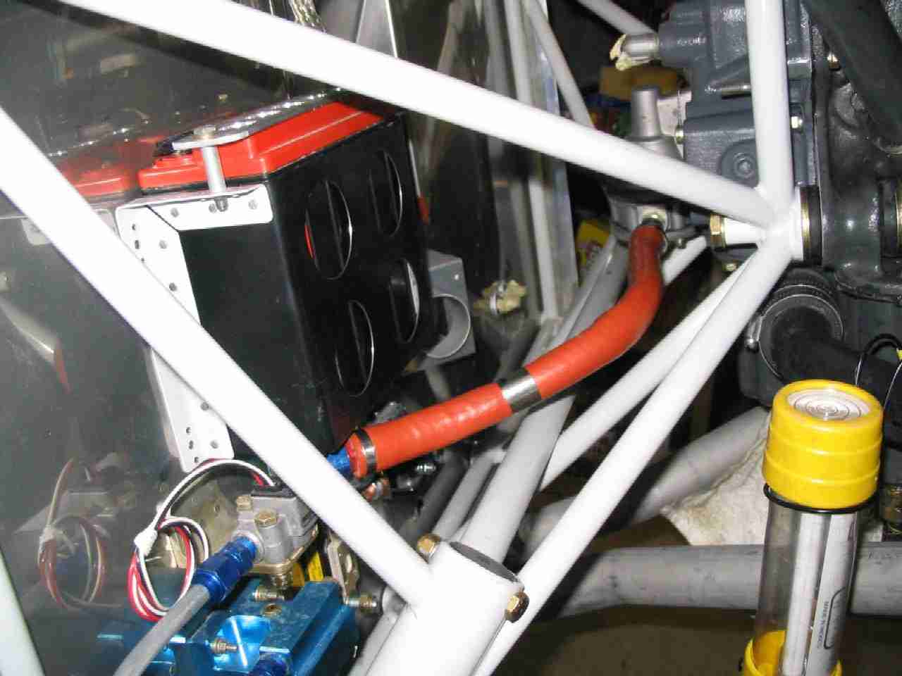
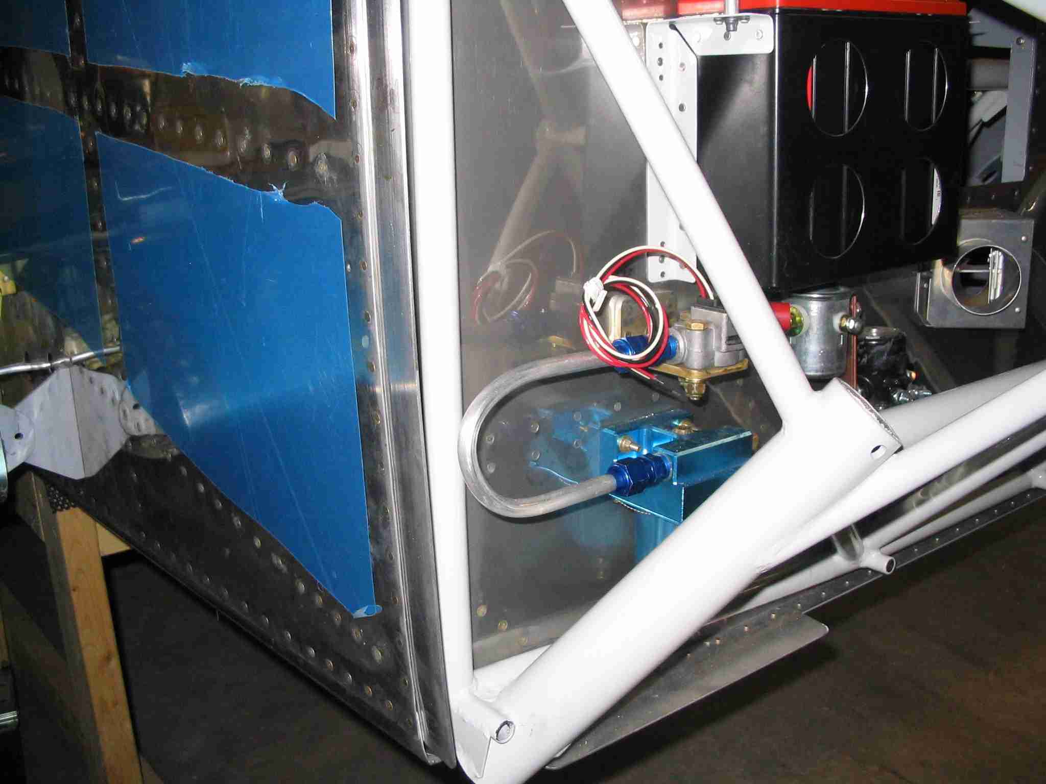
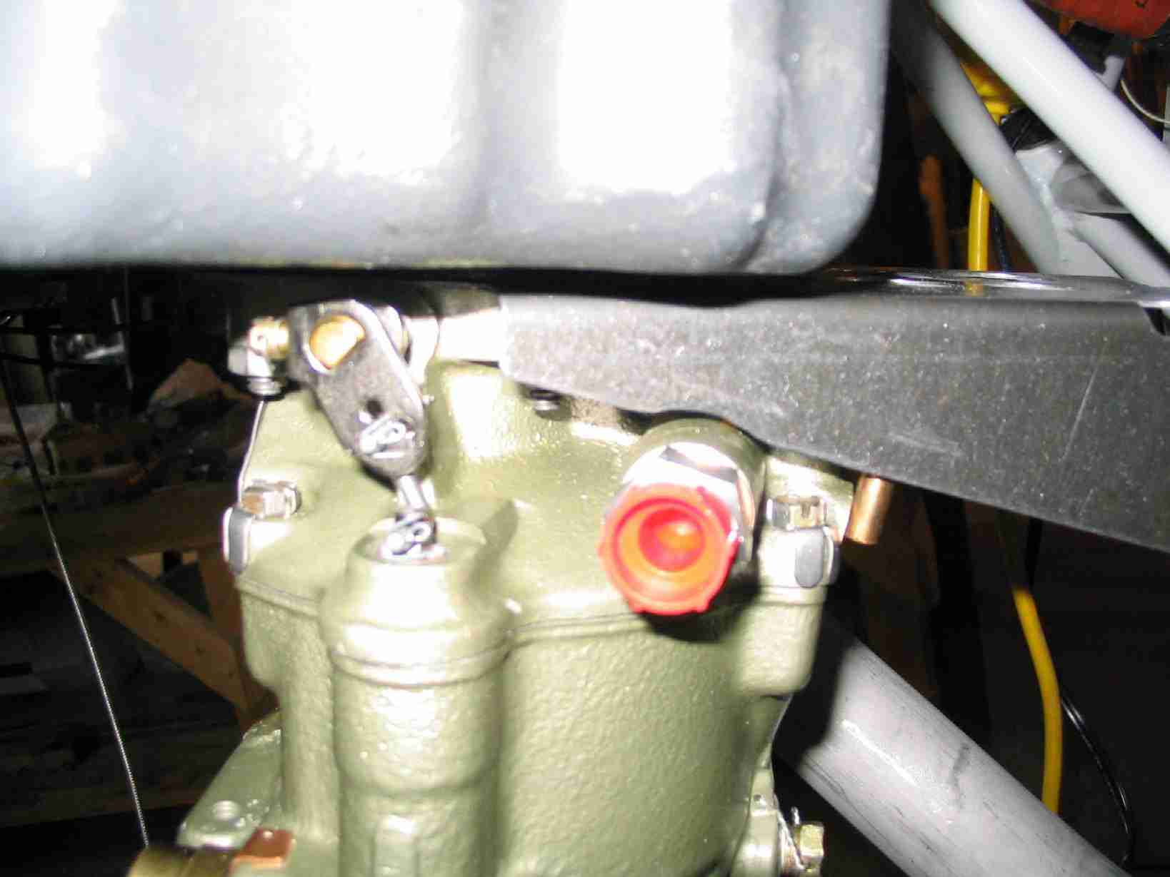
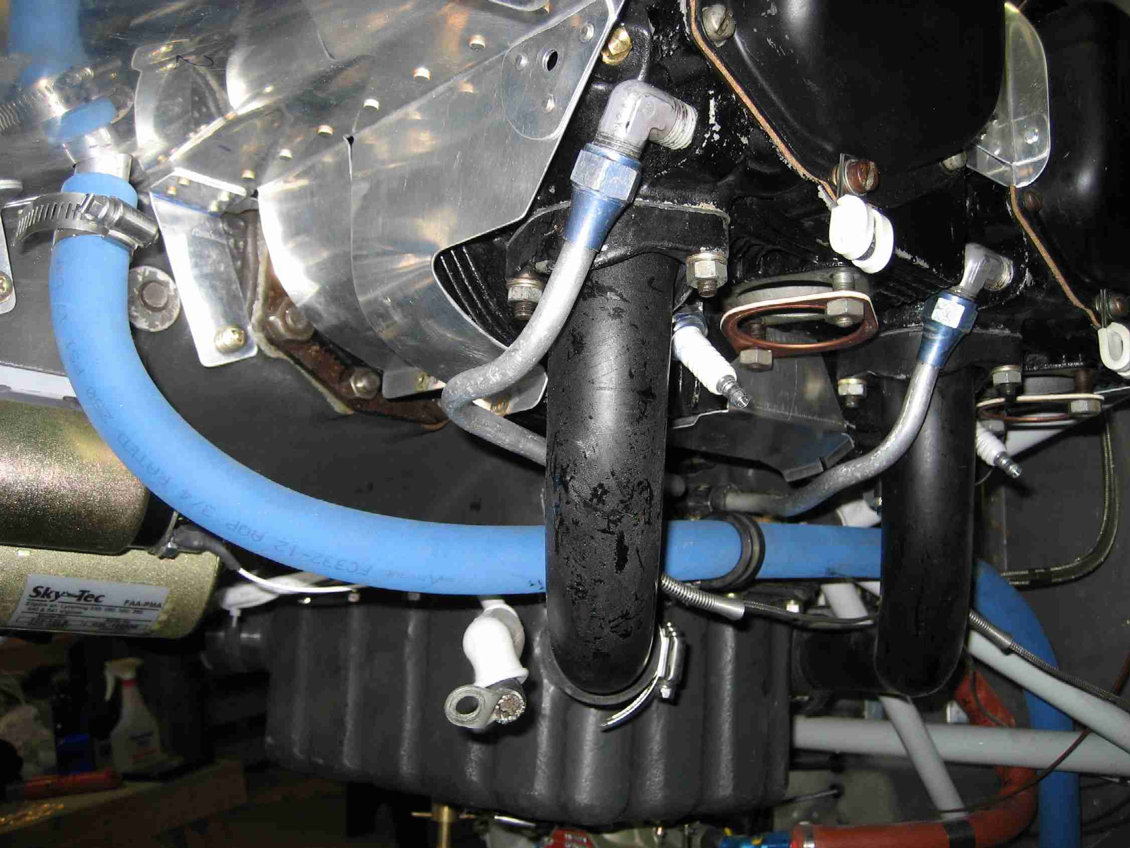
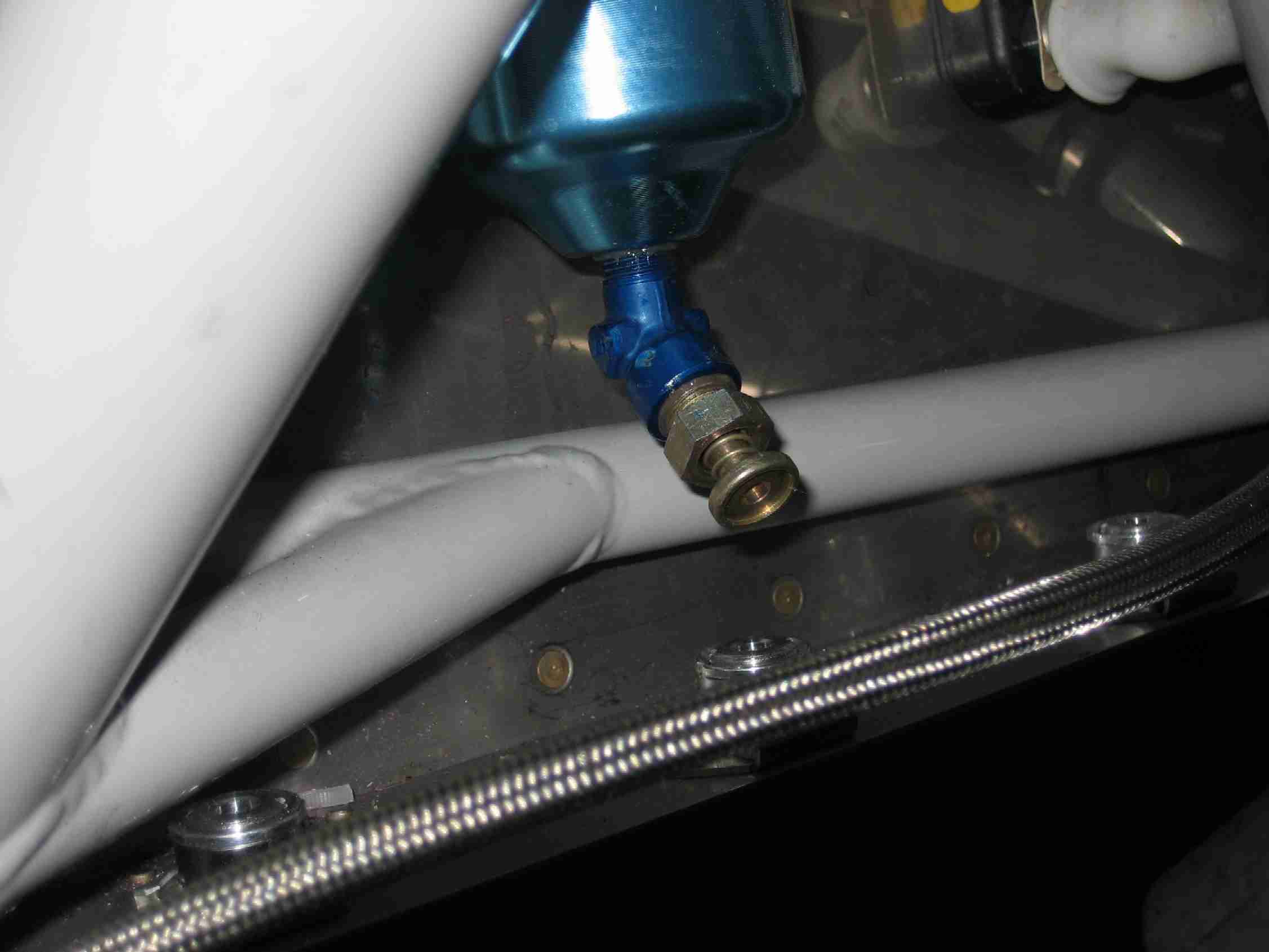
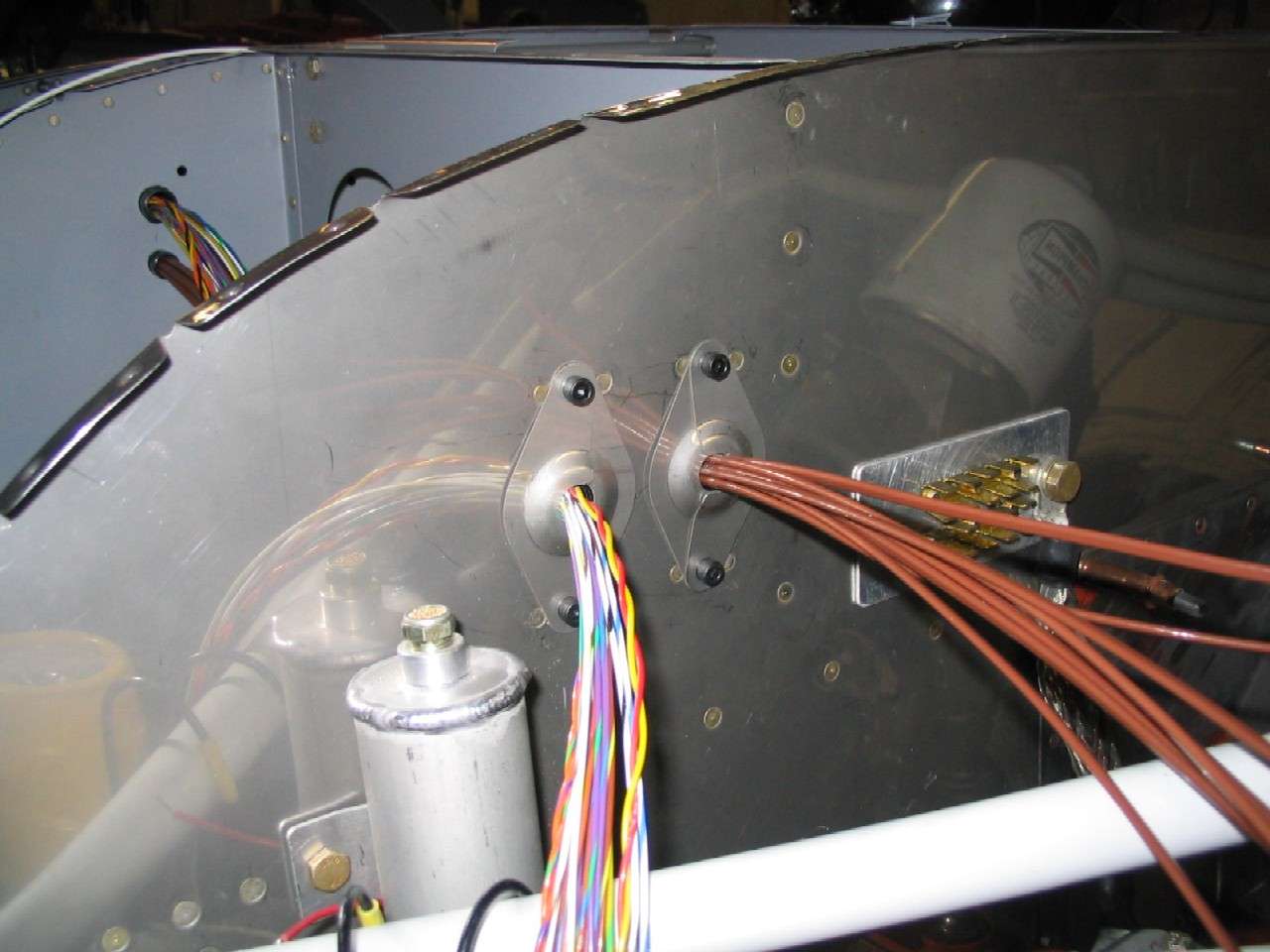
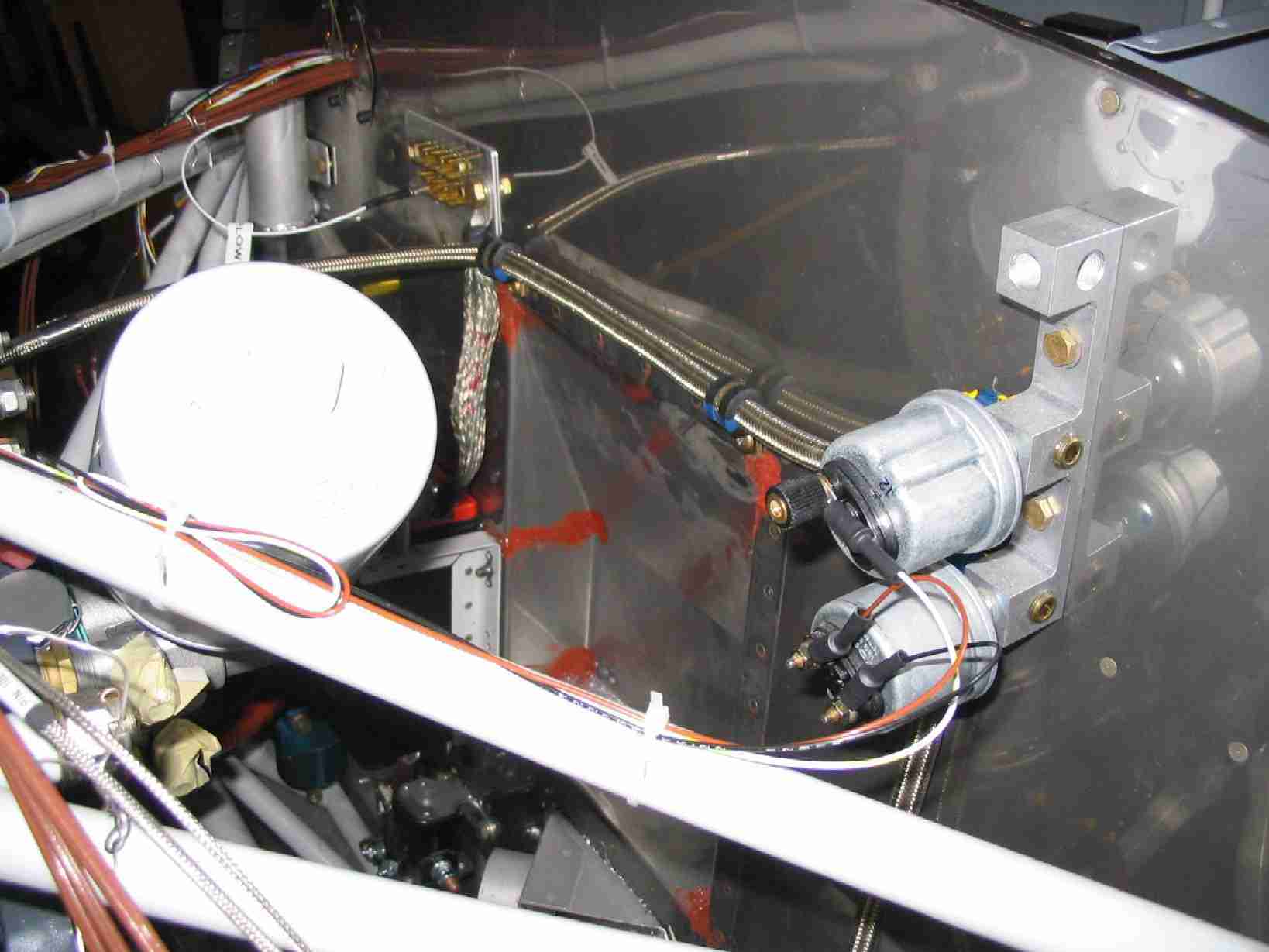
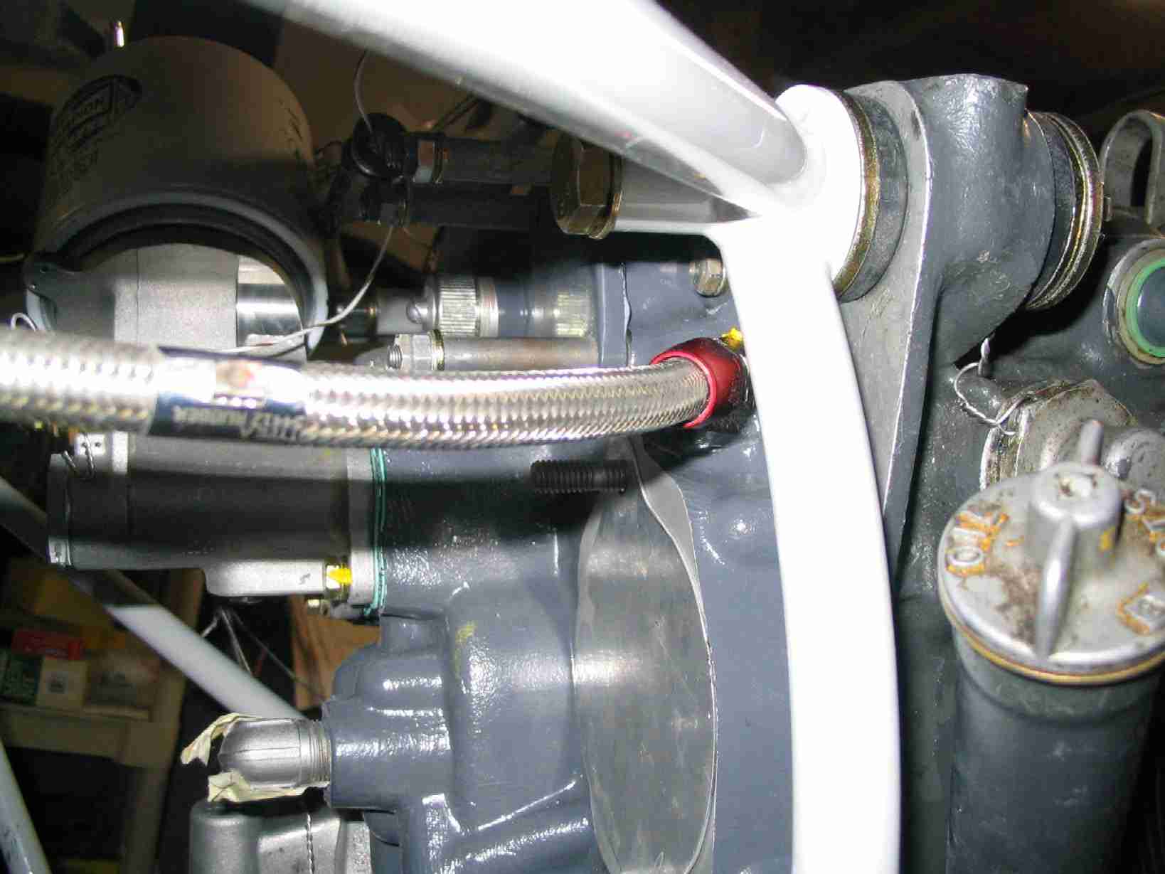
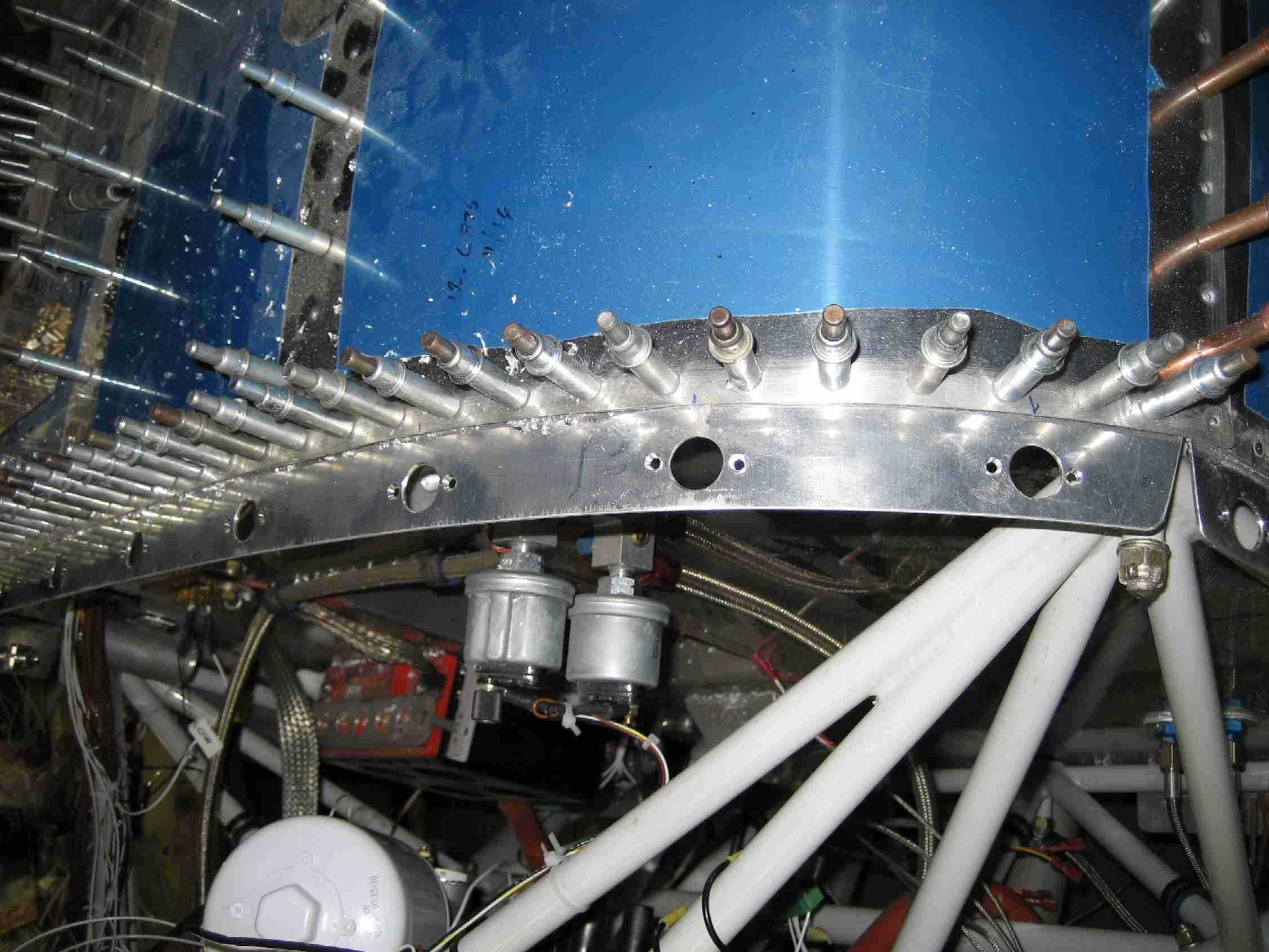
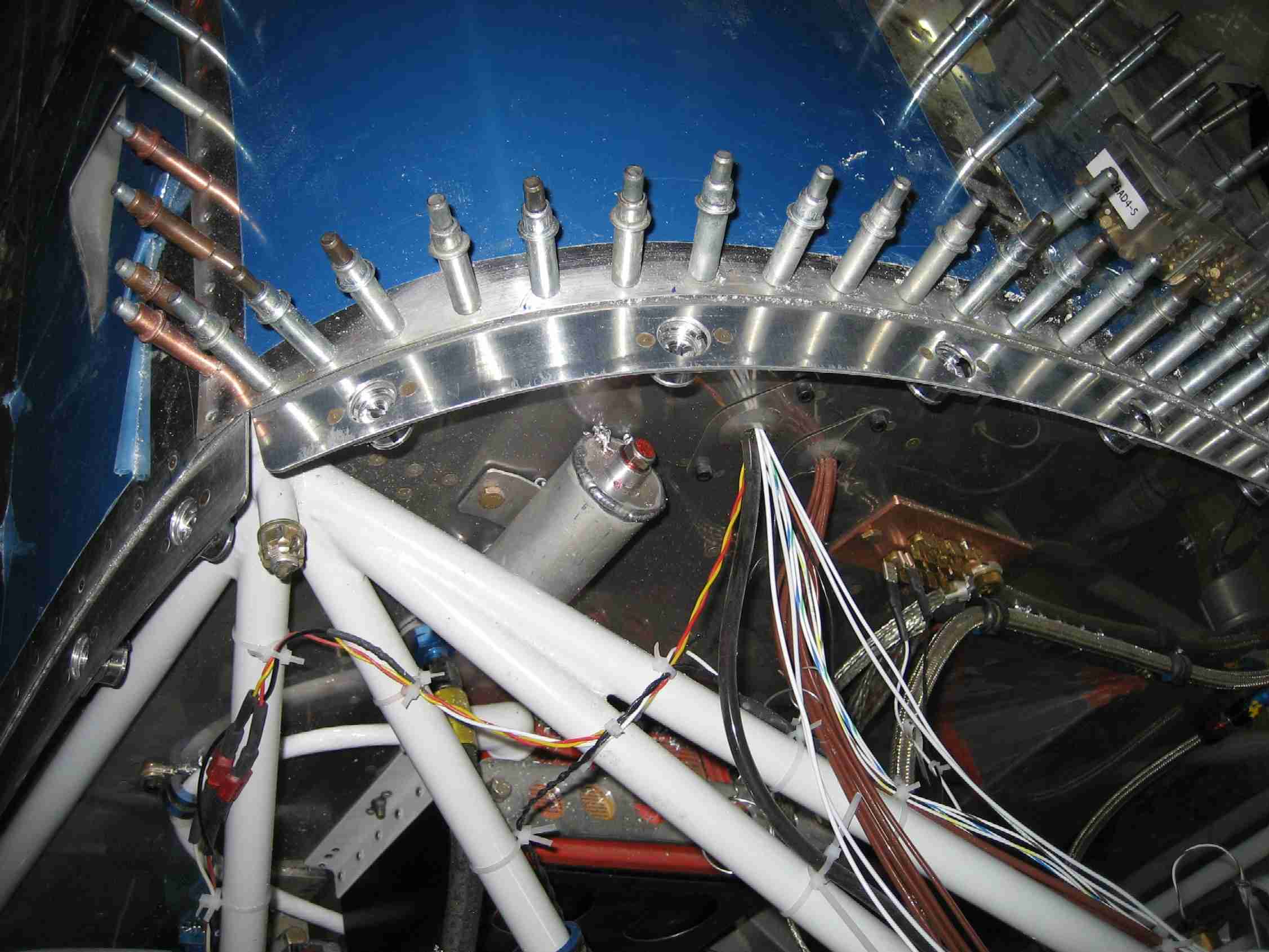
The fuel line was the first real connection between the engine and the
fuselage. (9/1/06) F
The fuel line was the first real connection between the engine and the
fuselage. (9/1/06) |
|
|
|
|
|
|
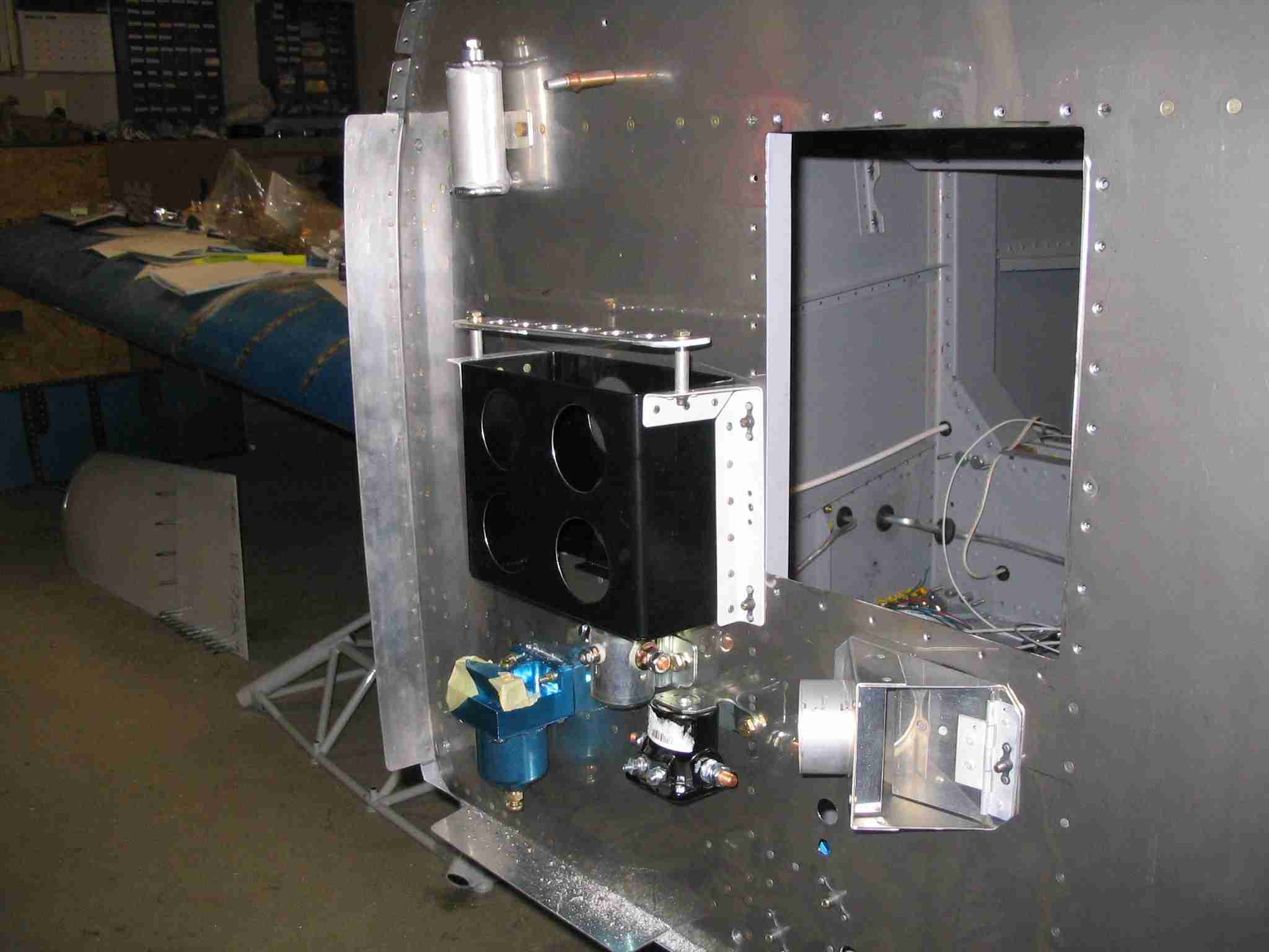
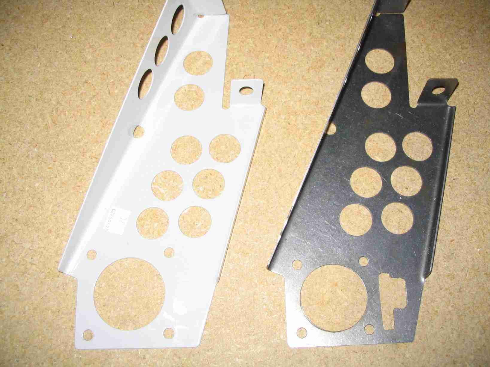
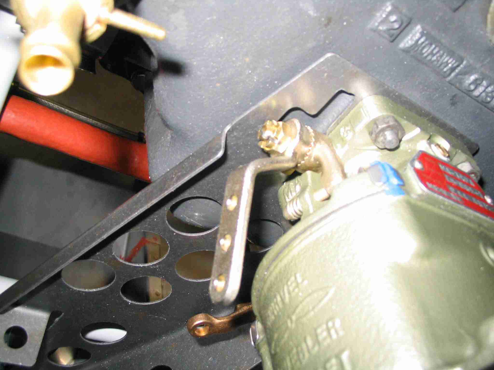
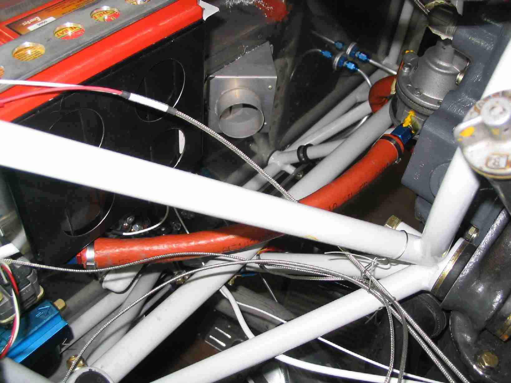
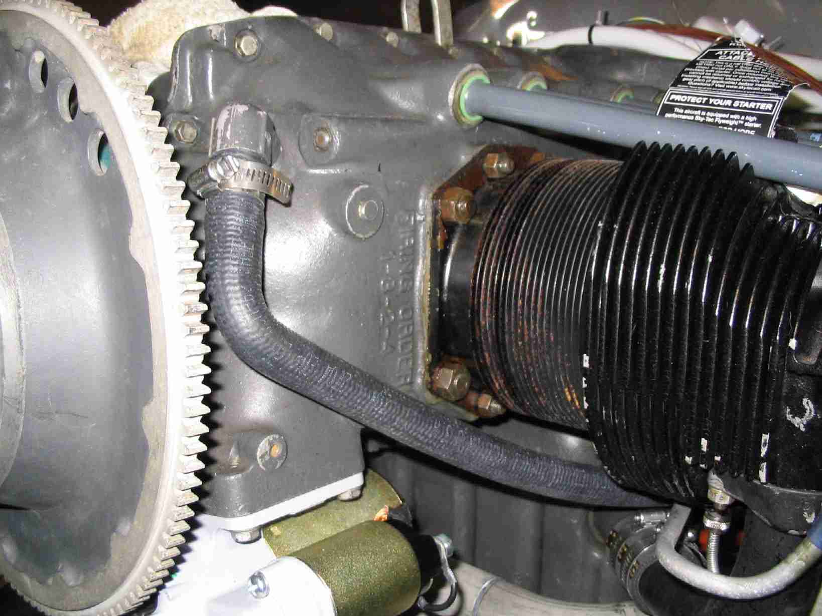
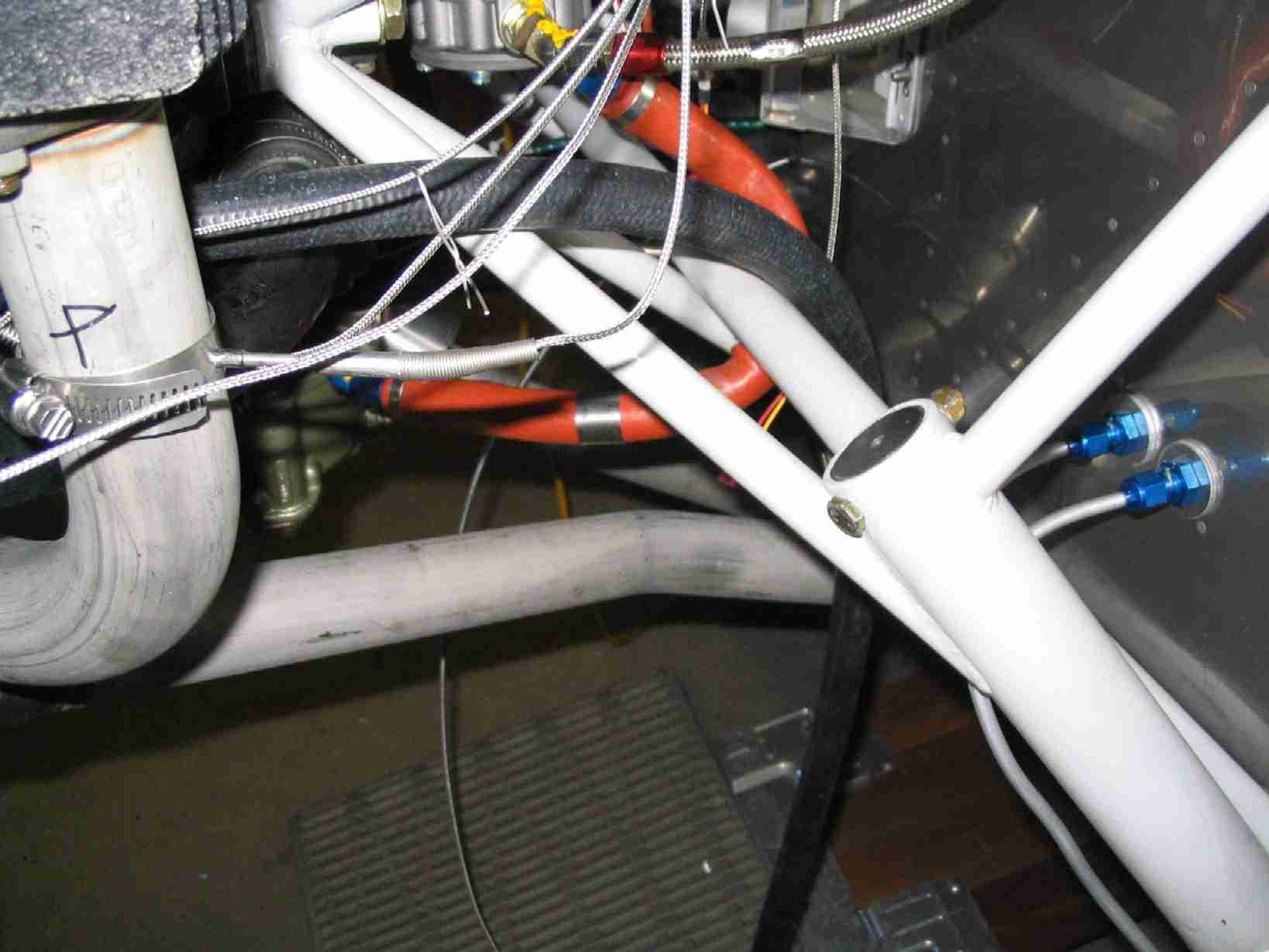
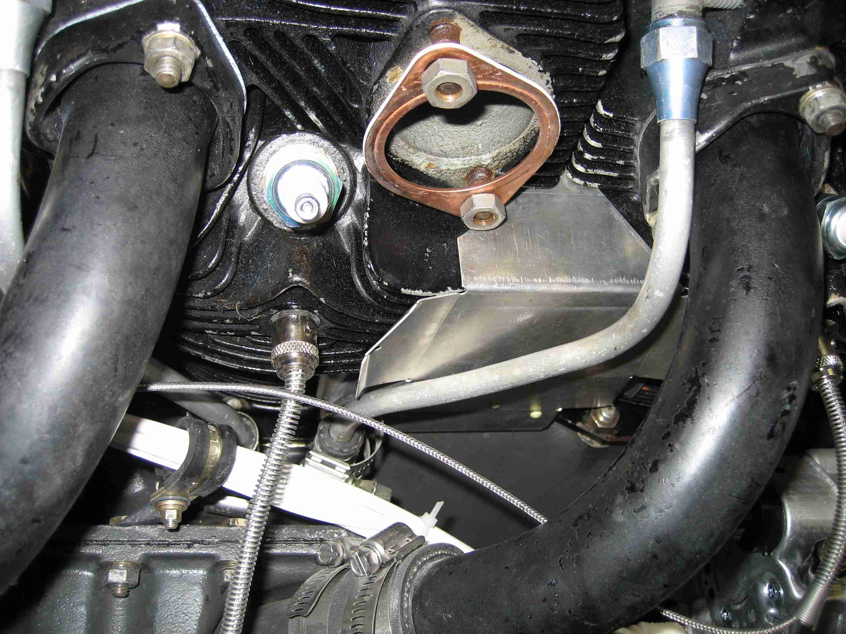
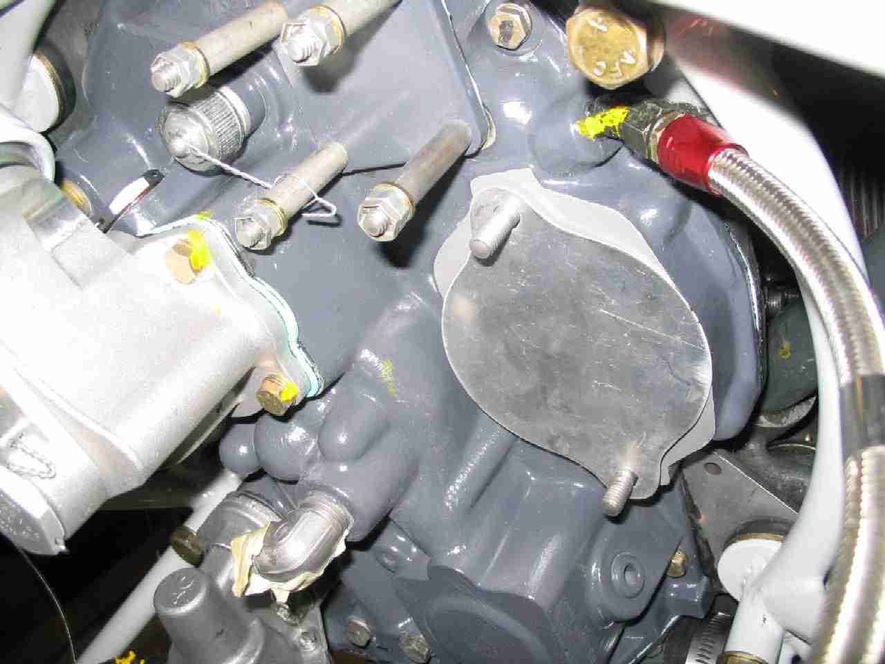
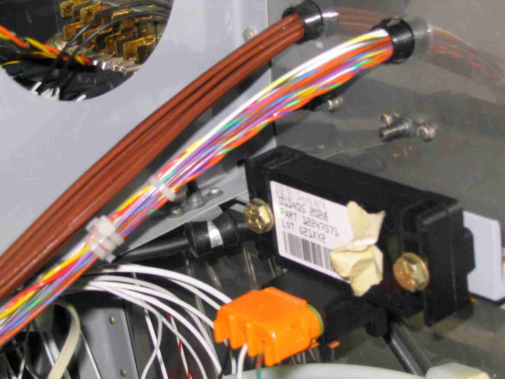
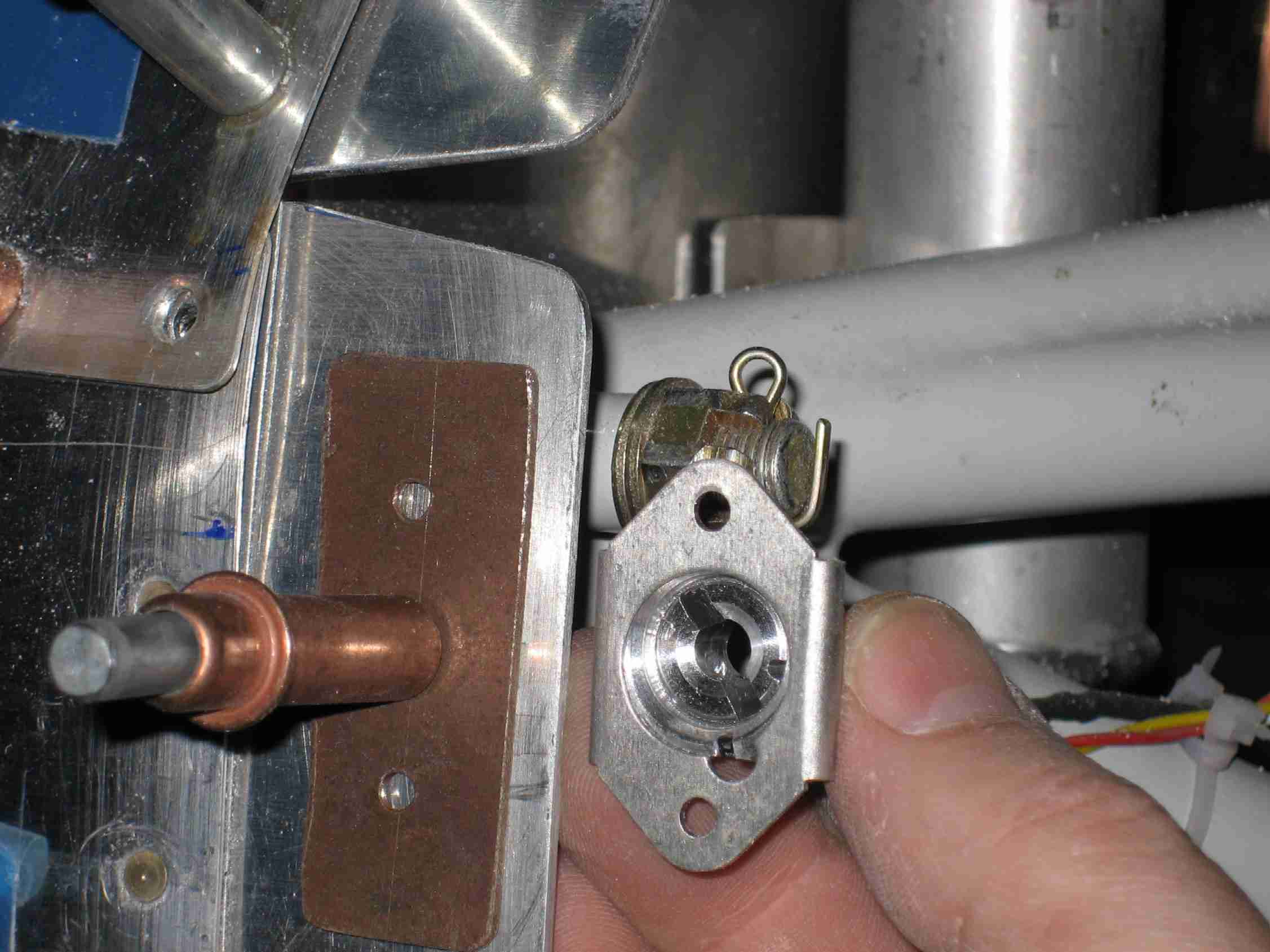
 F
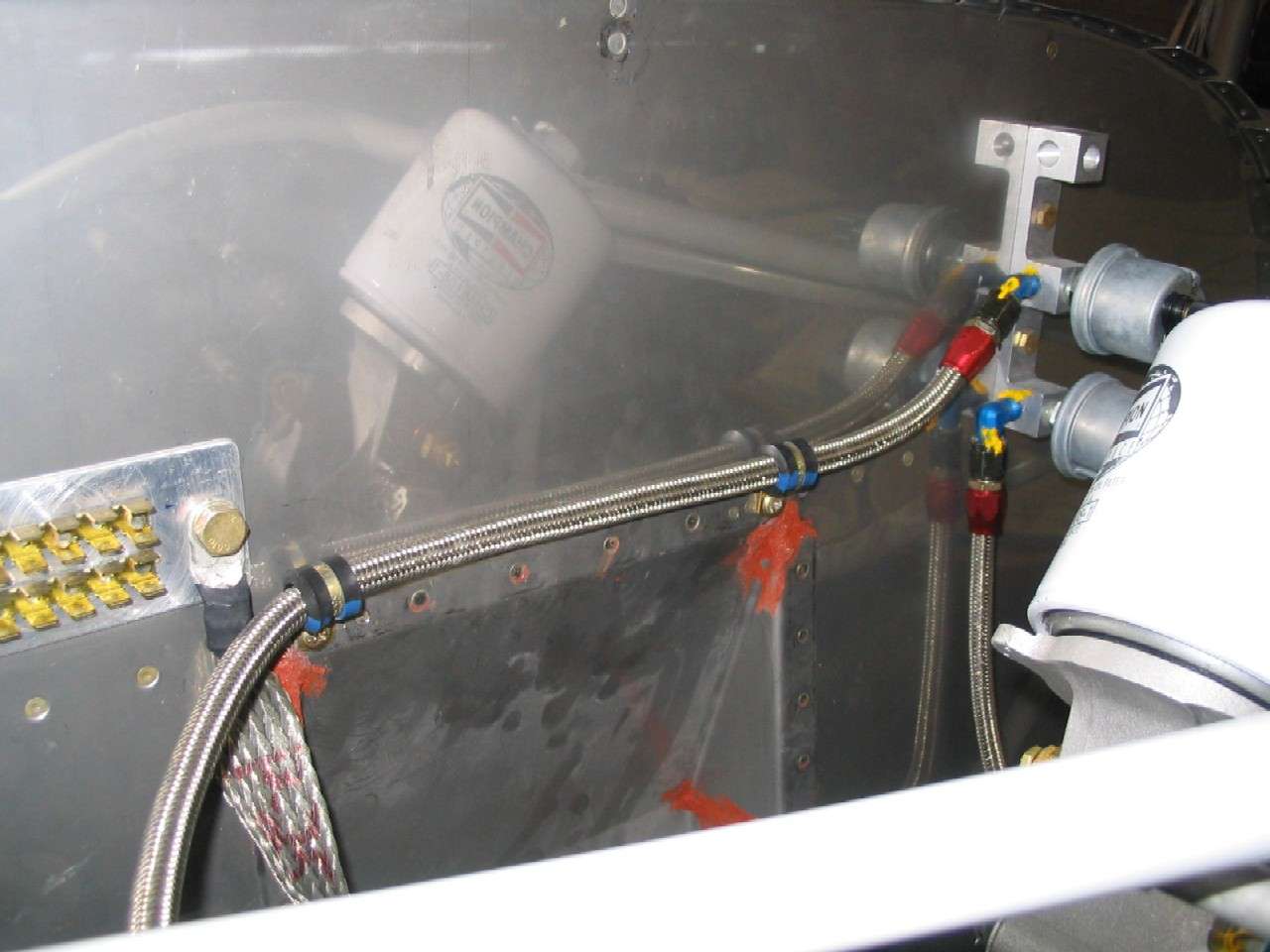
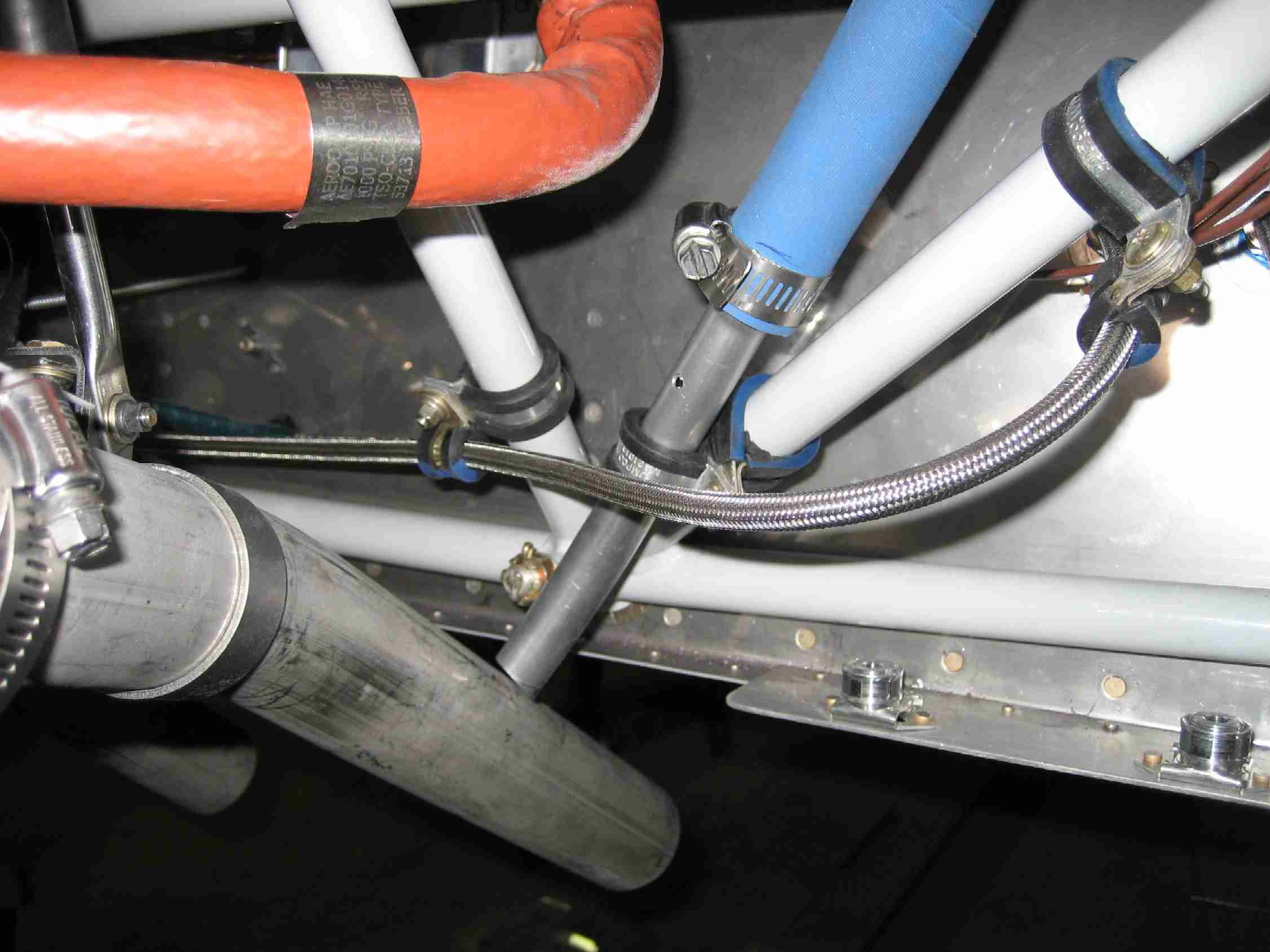
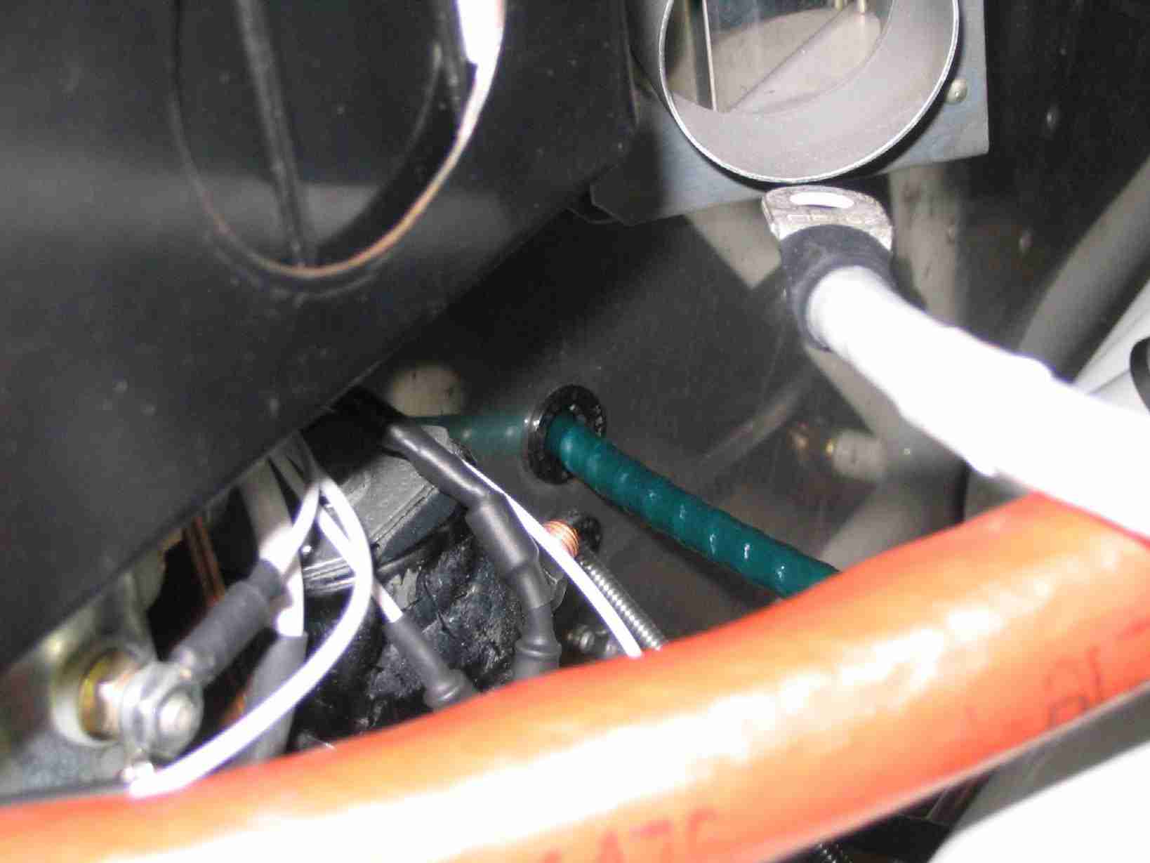
The oil line running between the engine and the transducer is held in
place by two Adel clamps that bolt through the firewall using AN3 sized
plate nuts (MS21051 - L3). I highly recommend installing these plate nuts prior to
riveting the firewall recess in place. There is limited space
available for the rivet gun once the engine is hung but you can easily
squeeze their rivets prior to installing the recess and engine. (9/6/06) F
The oil line running between the engine and the transducer is held in
place by two Adel clamps that bolt through the firewall using AN3 sized
plate nuts (MS21051 - L3). I highly recommend installing these plate nuts prior to
riveting the firewall recess in place. There is limited space
available for the rivet gun once the engine is hung but you can easily
squeeze their rivets prior to installing the recess and engine. (9/6/06) |
|
|
|
|
|
|
|
|
|
|
|
|
|
|
|
|
|
|
|
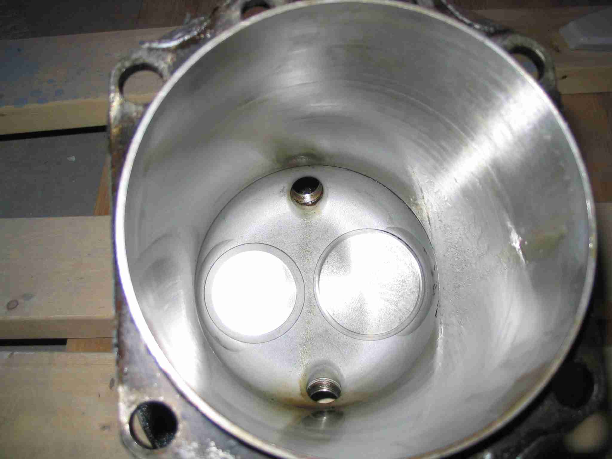
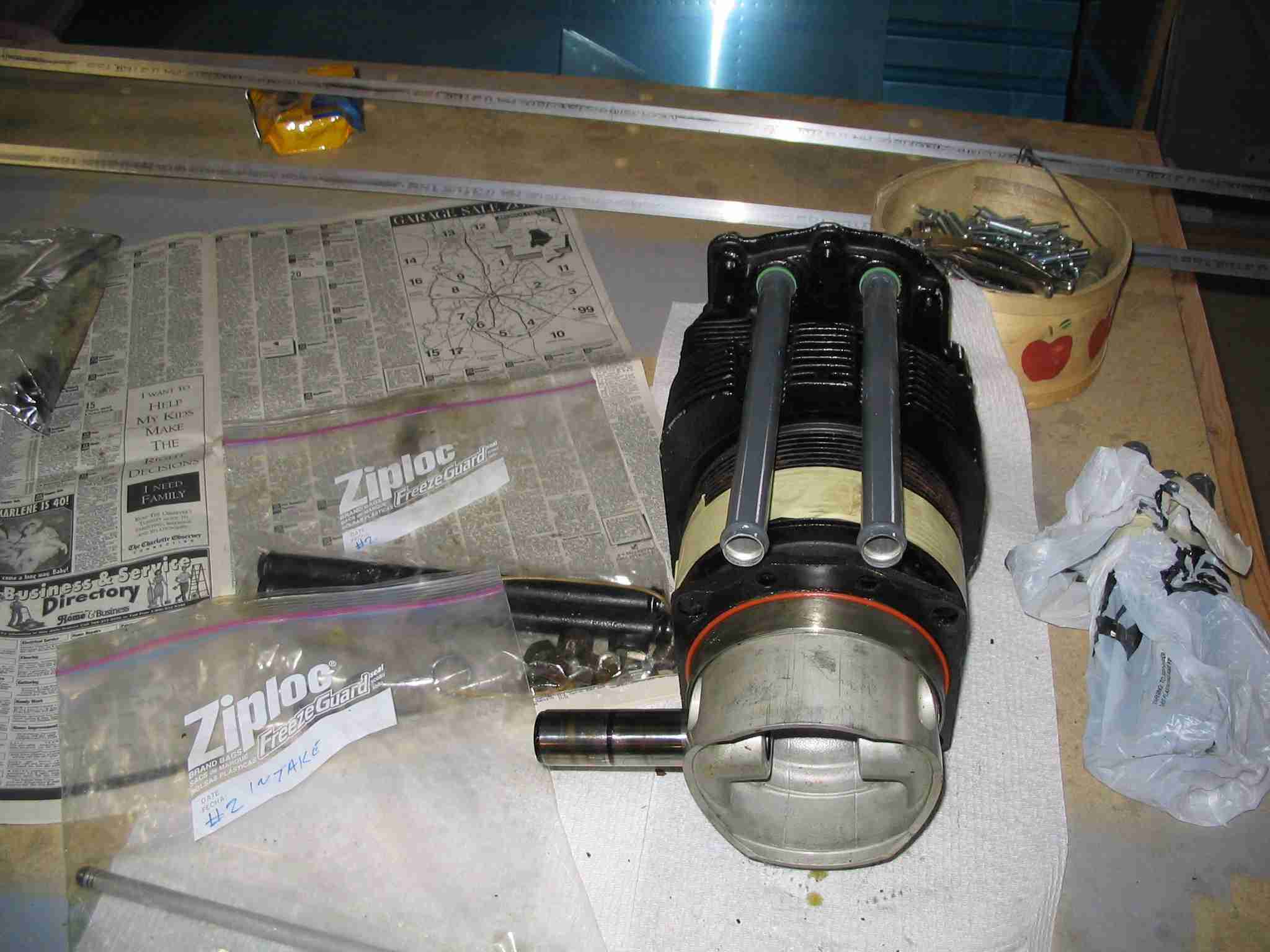
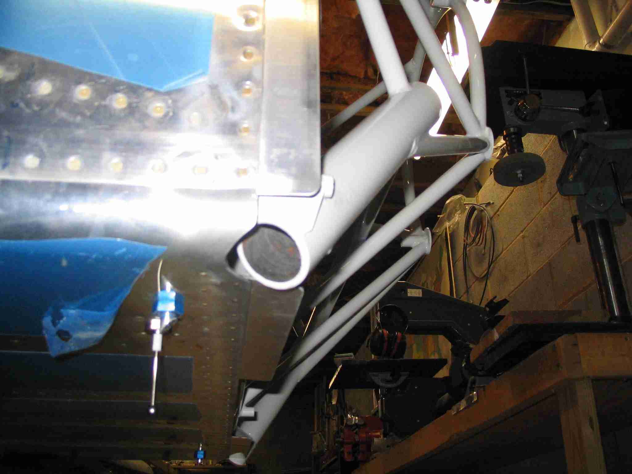
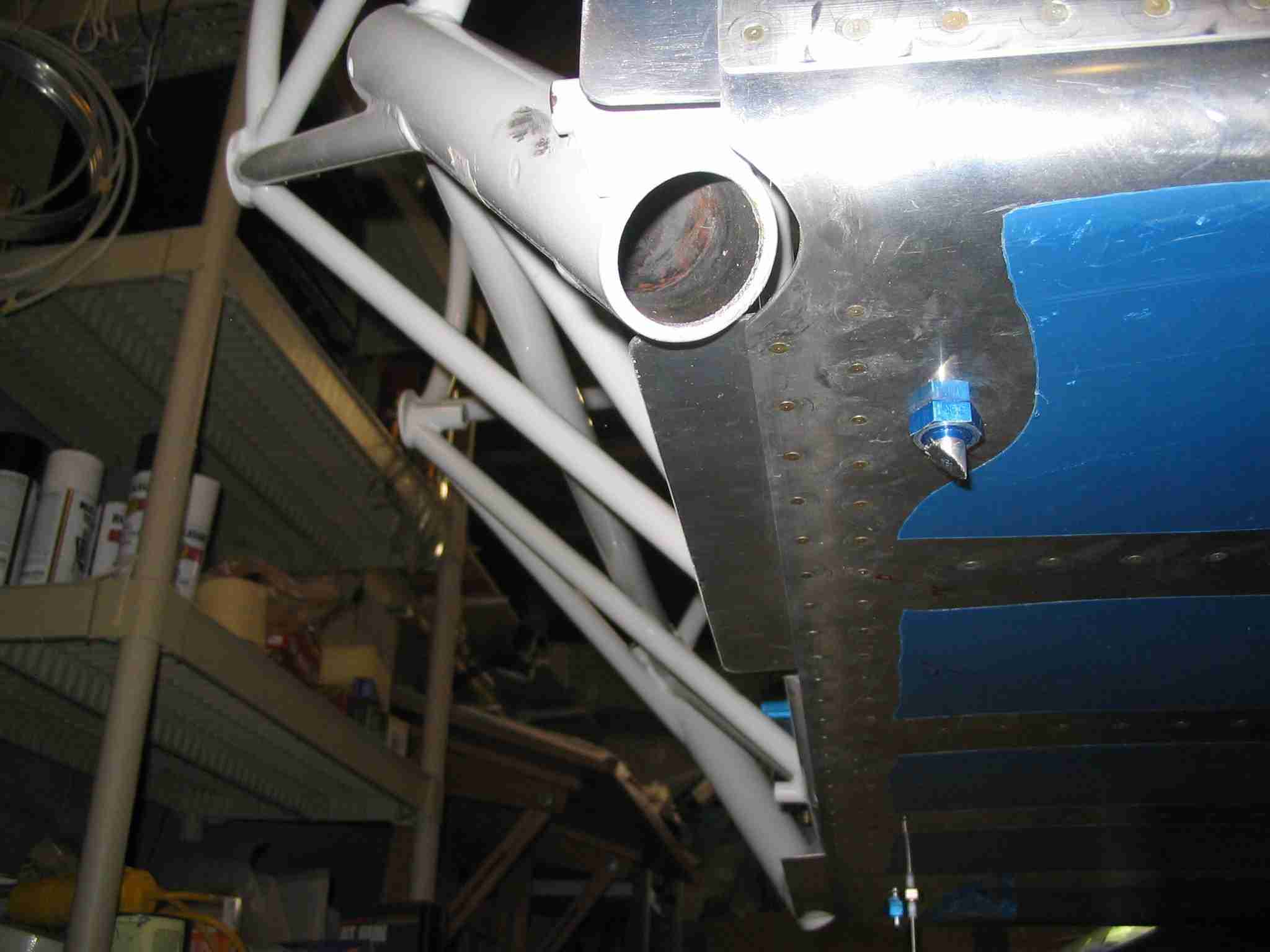
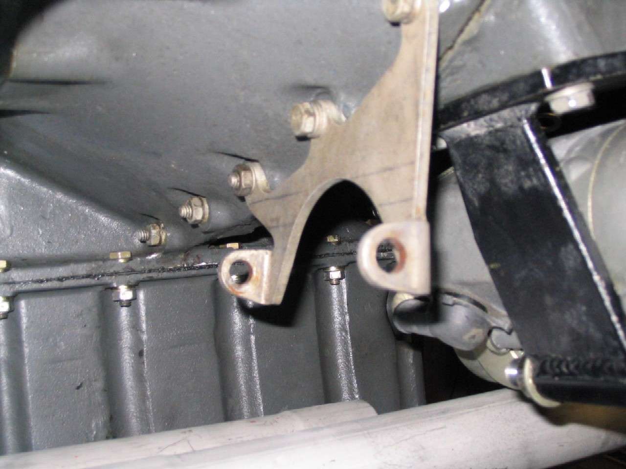
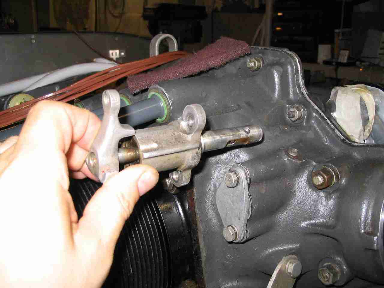
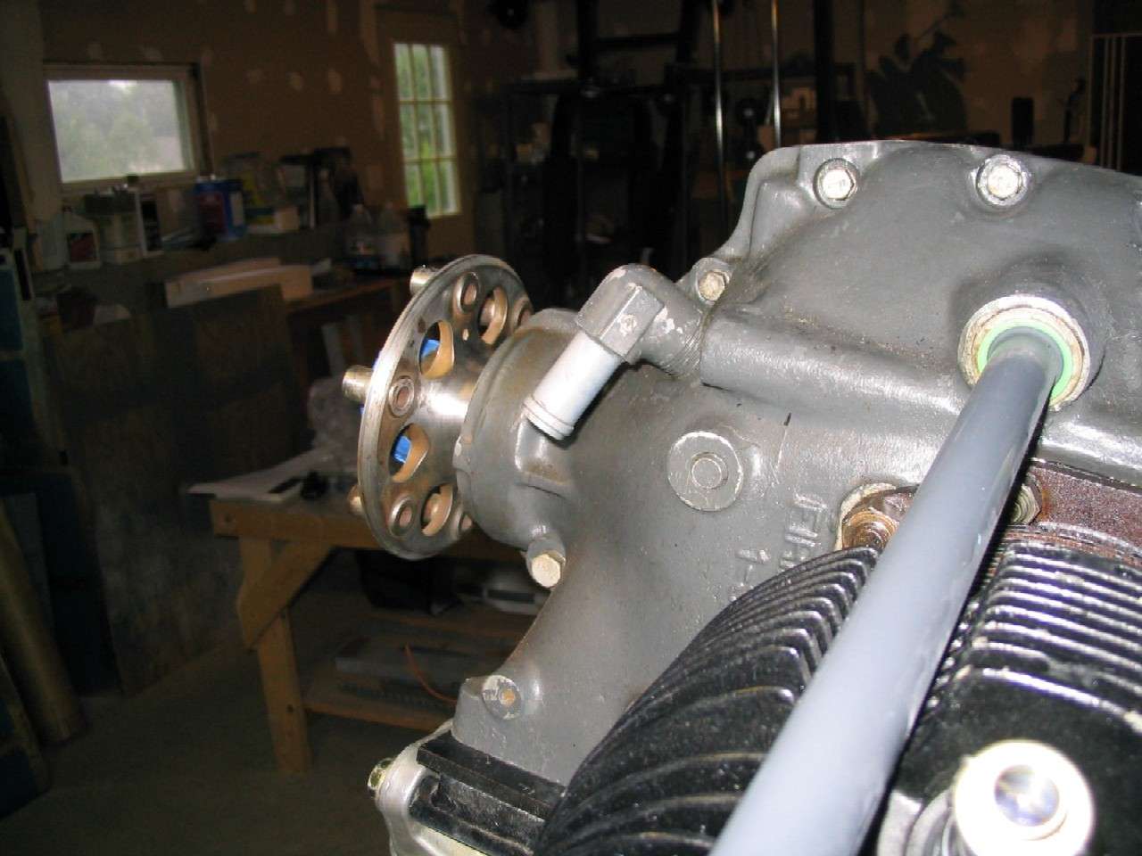
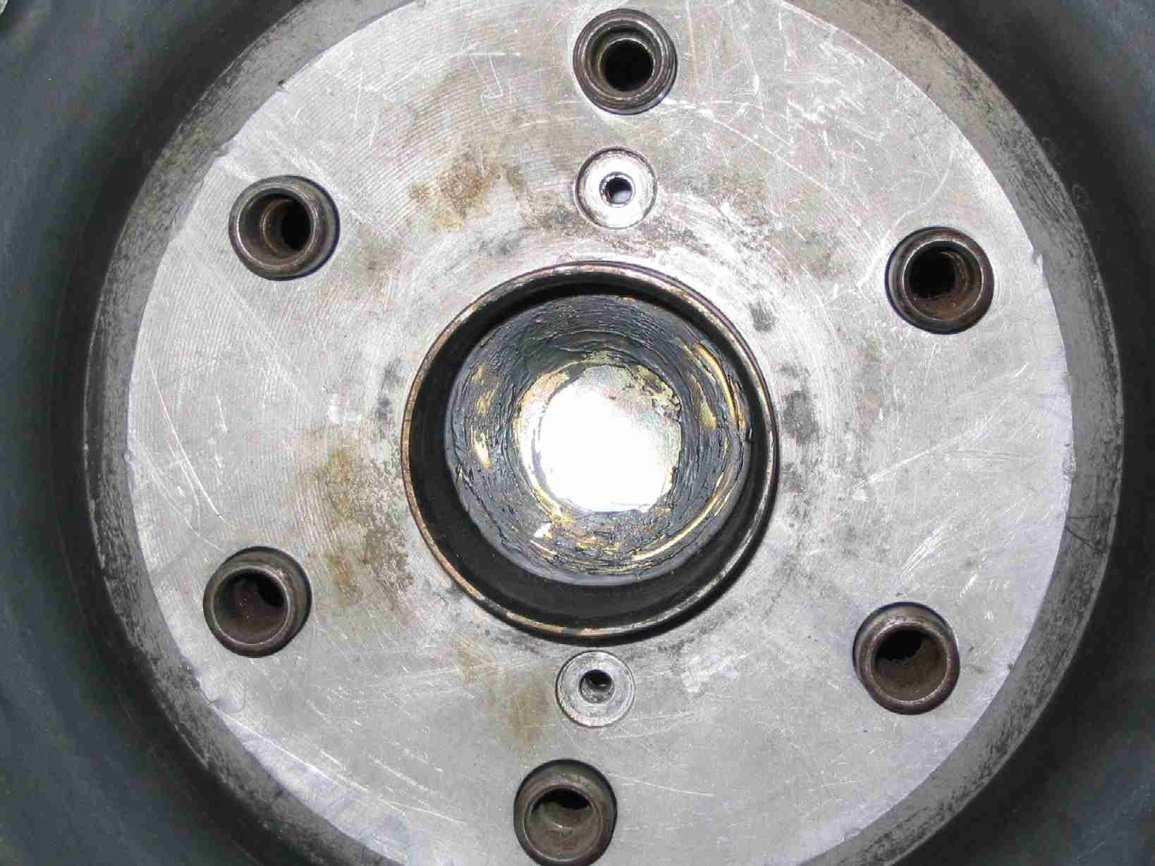
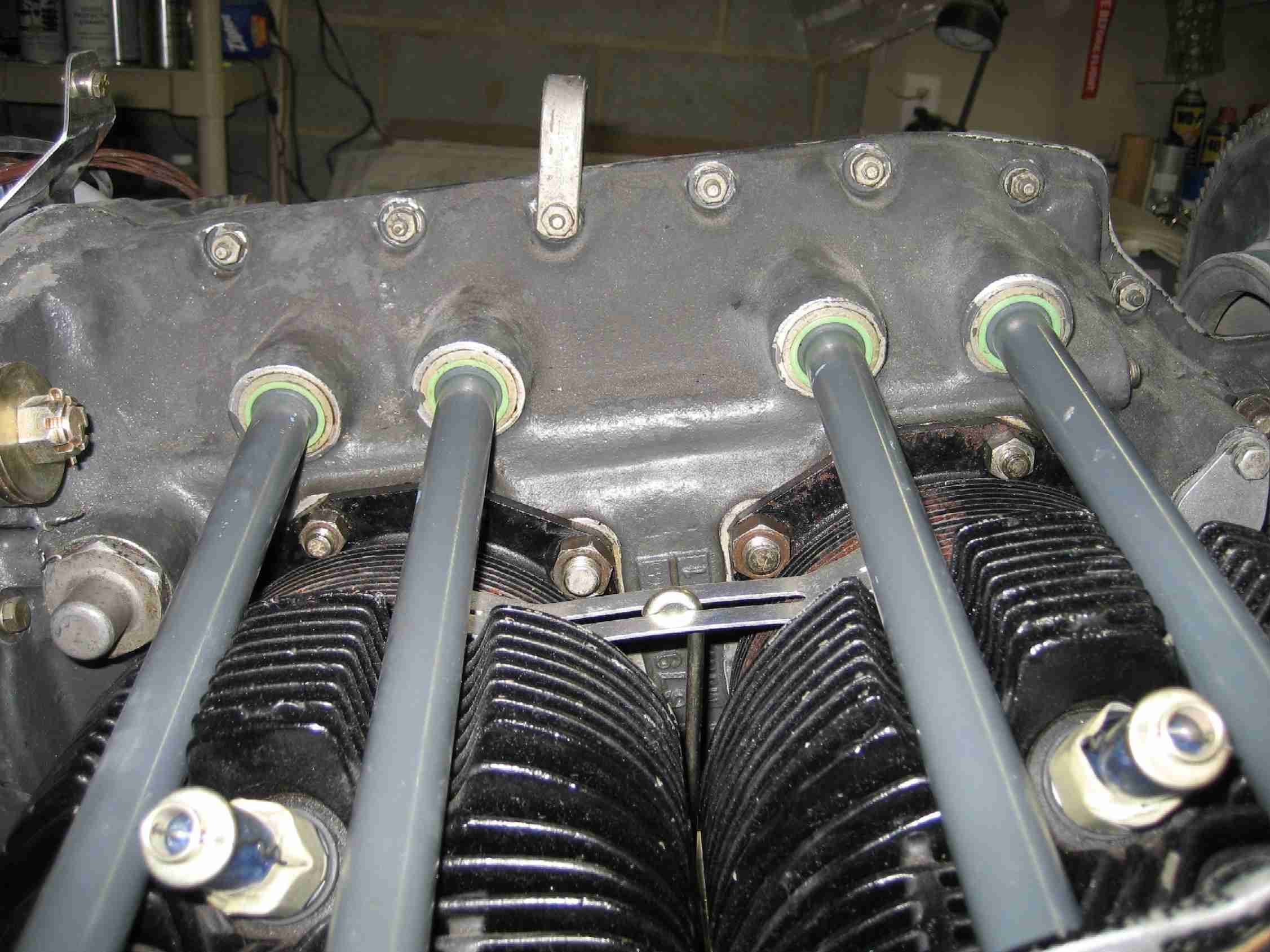
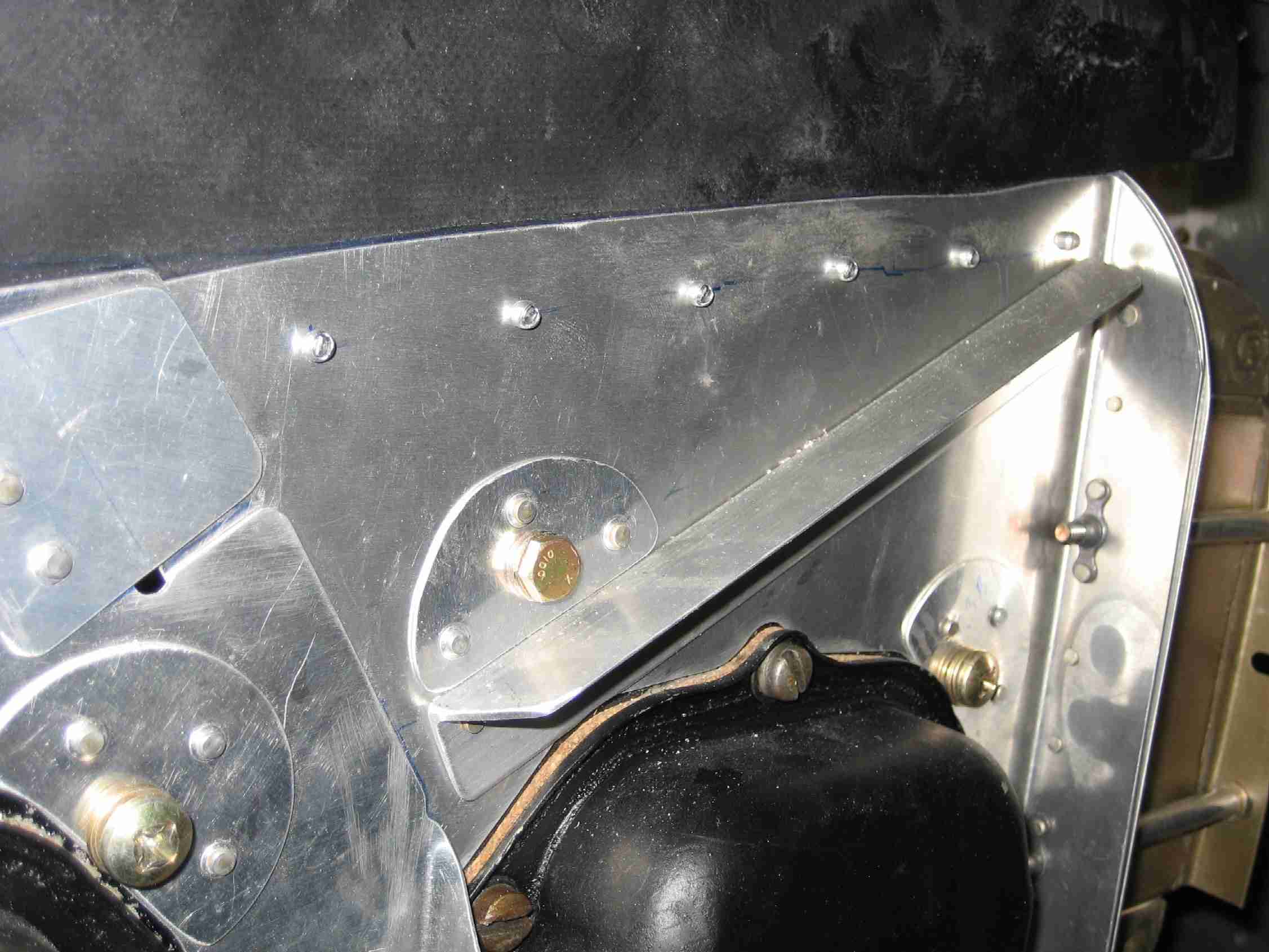
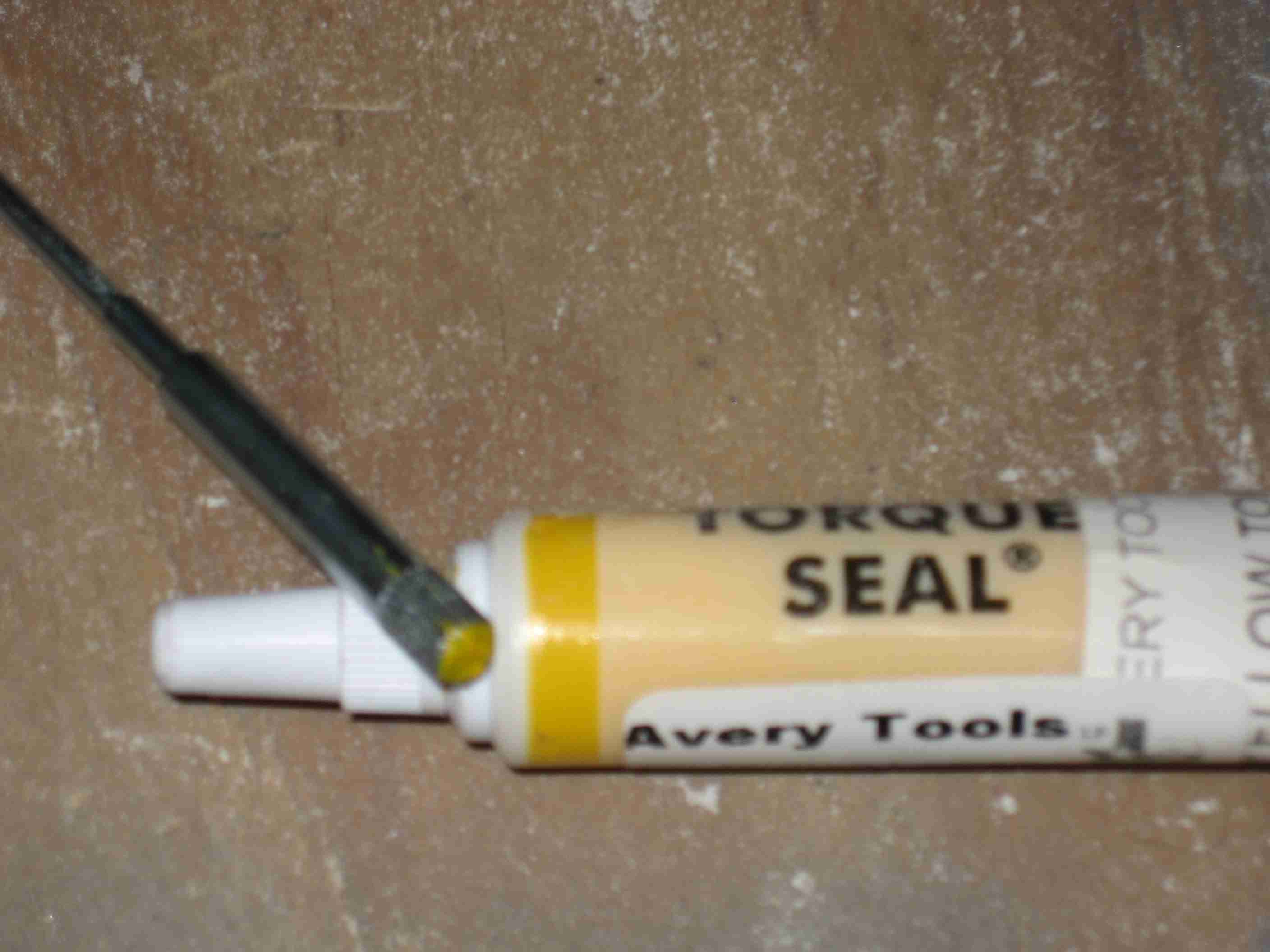
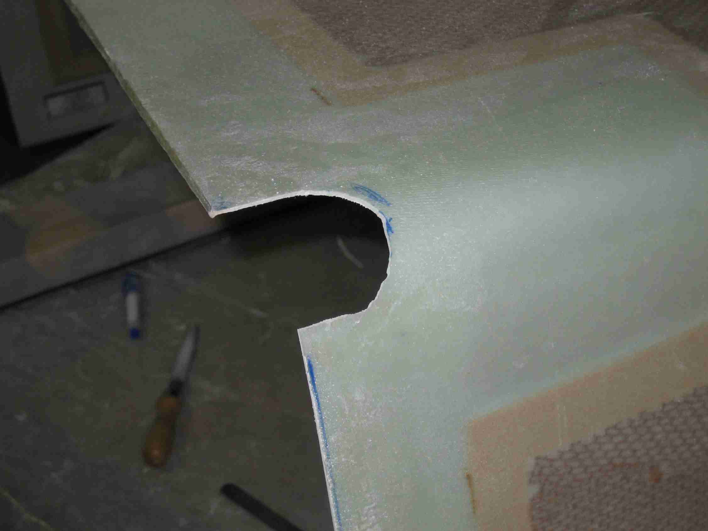
As mentioned earlier, my O-290-D2 was set up for a controllable pitch prop and like its cousins with a constant speed prop it some minor items must be addressed before installing a fixed pitch prop. The first thing that has to happen it to punch a hole in the plug six inches inside the crank. Do not drill this hole as you don't want to introduce mettle shavings into your engine. A long Phillips screwdriver and a big hammer did the trick for me. Then a plug has to be put into place. To install the plug I first cleaned the inside of the crank and then applied some gasket sealant, inserted the plug, convex side out. A section of axe handle was then inserted in the crank and hit with a small sledge hammer. This flattened the plug and formed the seal. With luck, I will have no leaks. The reason for doing all of this is that the crank has a small hole in it to feed oil to the prop so the pitch can be changed. Without the forward plug installed oil will just leak out the front of the prop. If you don't punch the hole in the aft seal, oil pressure will build up and push the forward seal out. The throttle/mixture bracket are off being powder coated, It should be back sometime next week. With its return, the carburetor will be installed. (10/7/06) |
|
|
|
|
|
|
|
|
|
|
|
|
|
|
|
|
|
|
|
|
|
|
|
|
|
|
|
|
|
|
|
|
|
|
|
|
|
|
|
|
|
|
|
|
|
|
|
|
|
|
|
|
|
|
|
|
.jpg)
.jpg)
.jpg)
Next Page F