| |
|
 E
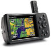
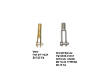
For navigation purposes, I plan on installing some type of handheld GPS
unit. This Garmin 296 is my current favorite, but that might change
by the time I get this thing in the air. E
For navigation purposes, I plan on installing some type of handheld GPS
unit. This Garmin 296 is my current favorite, but that might change
by the time I get this thing in the air. |
| |
| In addition to the items listed above, the
future N941WR will also have a communications radio, mode-C transponder,
intercom, CD player/changer for those longer flights, and an ELT. |
| |
| A good bit of time
has passed since I created this page. What that means is that I have
done a lot of daydreaming while deburring holes, pounding rivets, etc.
The CD player is out due to technical reasons and I might switch from the
Garman to a
Lowrance
AirMap 2000C. Is the Garmin unit better? It might be, but
is it double the price better? Unlikely.
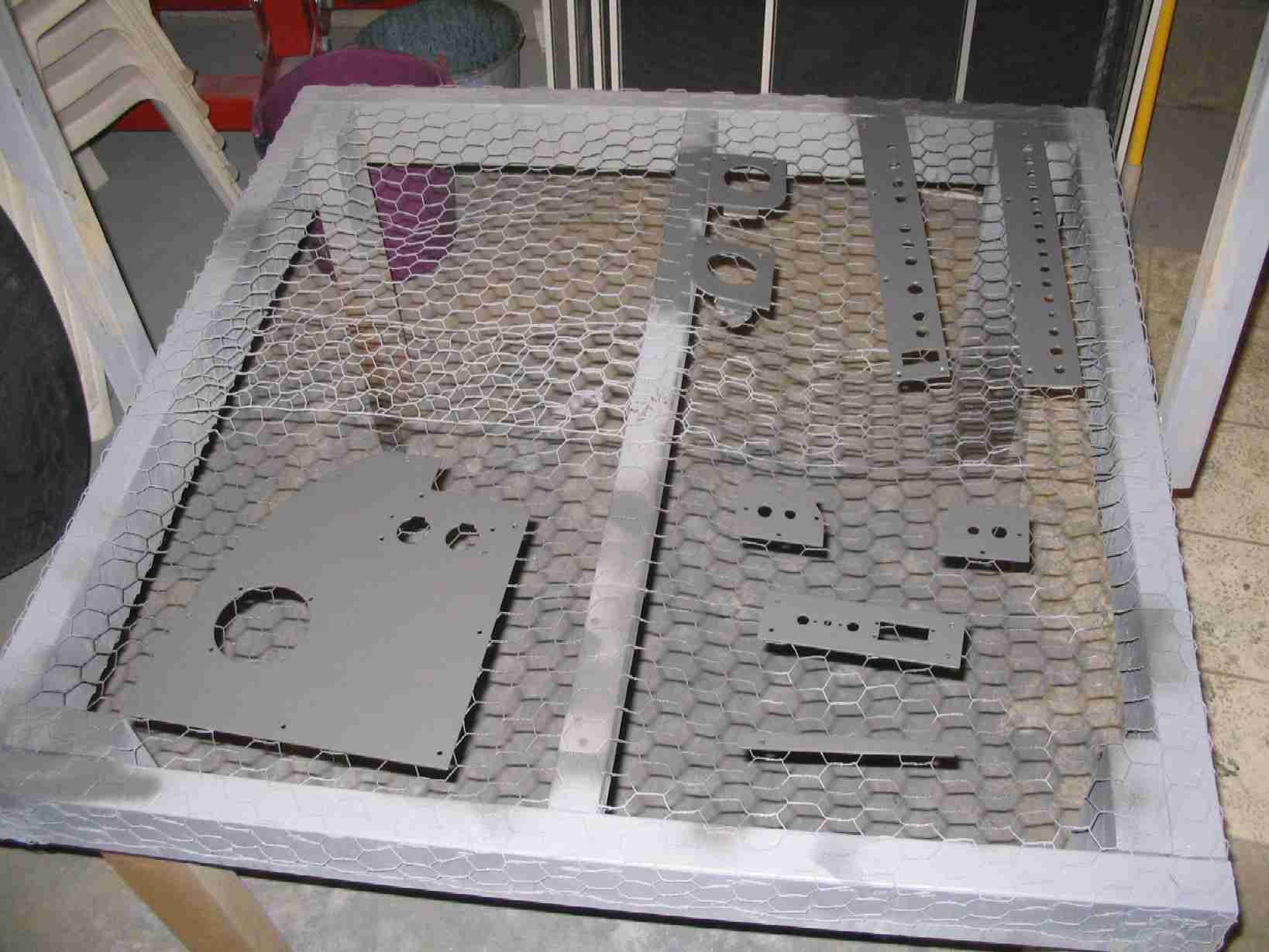
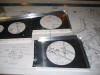
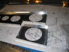
During some down time while working on the
fuselage I started prep work on the
Affordable Panels panel. Nothing special, just deburring and
cutting holes for the headphone jacks. (6/27/05) |
| |
|
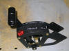  F
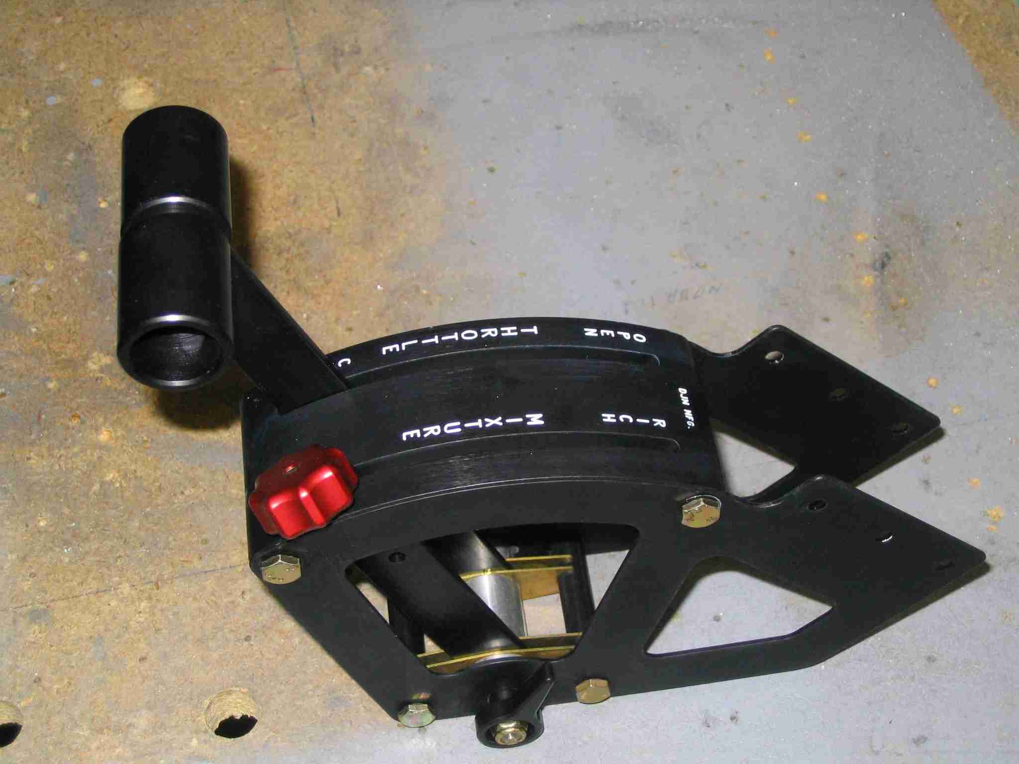
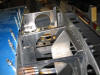
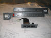
I've had a lot of questions about the throttle quadrant I purchased from
Aircraft Spruce so I thought I would post some pictures. The two
lever throttle quadrant is 2" wide and will not interfere with the radio
stack, as positioned by the Affordable Panels panel. The quadrant
looks very well made and as a nice smooth action and a friction lock. F
I've had a lot of questions about the throttle quadrant I purchased from
Aircraft Spruce so I thought I would post some pictures. The two
lever throttle quadrant is 2" wide and will not interfere with the radio
stack, as positioned by the Affordable Panels panel. The quadrant
looks very well made and as a nice smooth action and a friction lock.
The 2" Gasper vents were a gift and I think they will work very nice.
I'm sure the panel layout will change now that
Dynon offers 7" EFIS and EMS displays. I do know the Garmin GPS will
be mounted above the radios. (7/26/05) |
| |
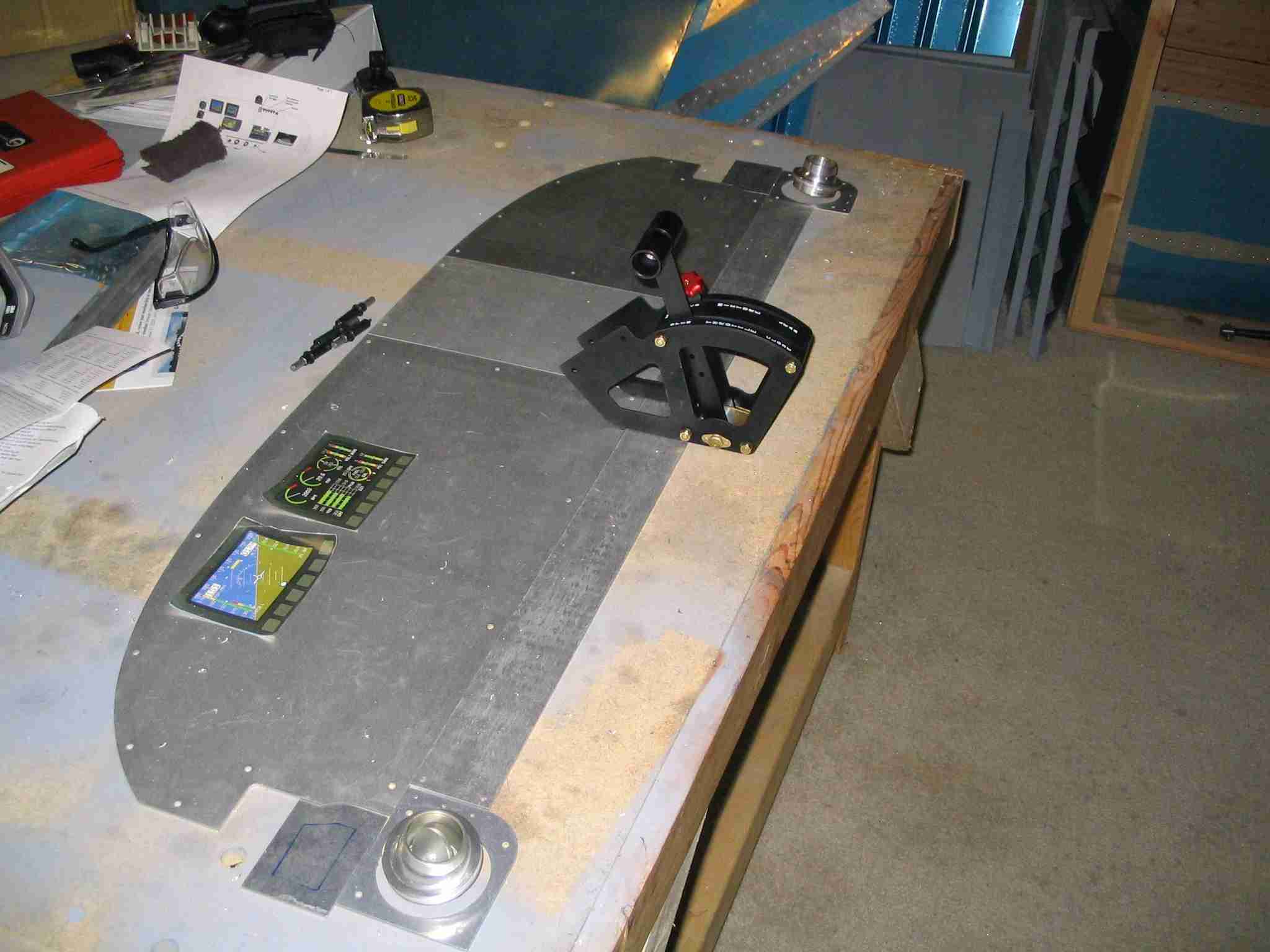
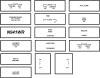
G I
think this is how might install the throttle quadrant on my -9. The
drawing is a bit rough but I think you should get the idea. (There
are actually three AN-3 bolts per side that will hold the quadrant in
place, not two.) If you have experience installing one in a -6, 7,
or 9 I would like to hear how you did it. (7/30/05) |
| |
|
 E
There is one good thing about aircraft building, you have the option of
changing your mind a million times before you start cutting aluminum.
Panel layout number four is now under consideration. (Never mind it
shows the Cessna style throttle, I will install the throttle quadrant
described above.) The GPS moved over to the top of the radio stack
so I don't have to look down for my navigational aid and my passenger /
co-pilot / wife can use it while in flight. The deciding factor for
this change was the availability of
AirGizmos Panel Dock for Garmin 196 & 296 hand held GPS. (8/9/05) E
There is one good thing about aircraft building, you have the option of
changing your mind a million times before you start cutting aluminum.
Panel layout number four is now under consideration. (Never mind it
shows the Cessna style throttle, I will install the throttle quadrant
described above.) The GPS moved over to the top of the radio stack
so I don't have to look down for my navigational aid and my passenger /
co-pilot / wife can use it while in flight. The deciding factor for
this change was the availability of
AirGizmos Panel Dock for Garmin 196 & 296 hand held GPS. (8/9/05) |
| |
|
 F
These Gasper vents were a gift from a friend and will look very nice on
each corner of the instrument panel. They are much better than the
junk plastic vents supplied with the kit. (8/13/05) F
These Gasper vents were a gift from a friend and will look very nice on
each corner of the instrument panel. They are much better than the
junk plastic vents supplied with the kit. (8/13/05) |
| |
|
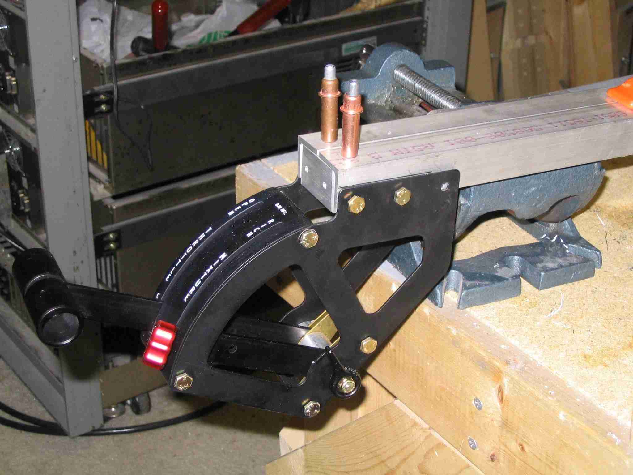
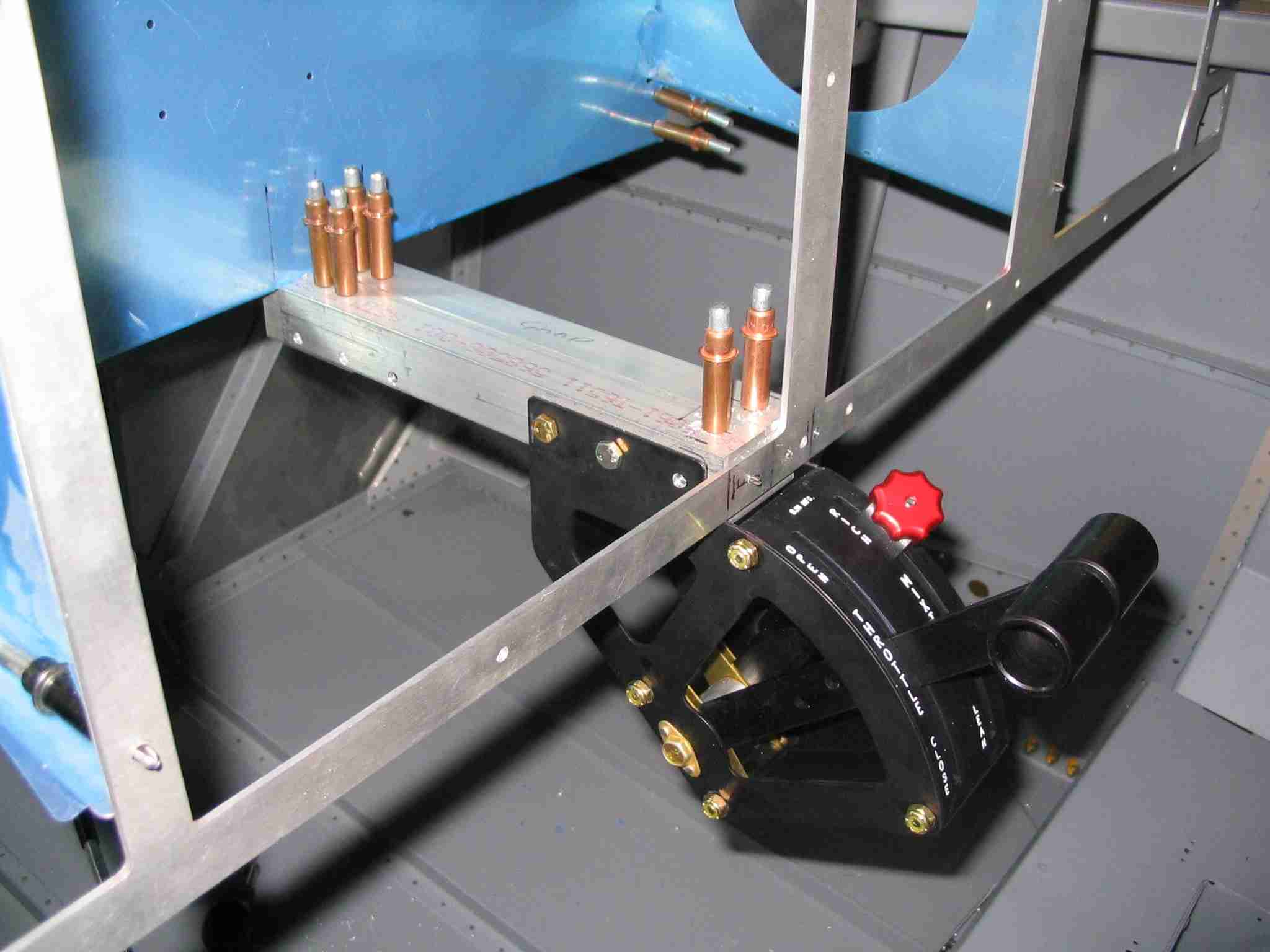
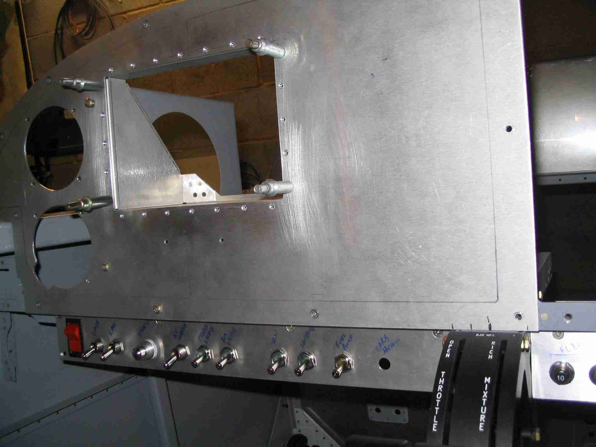
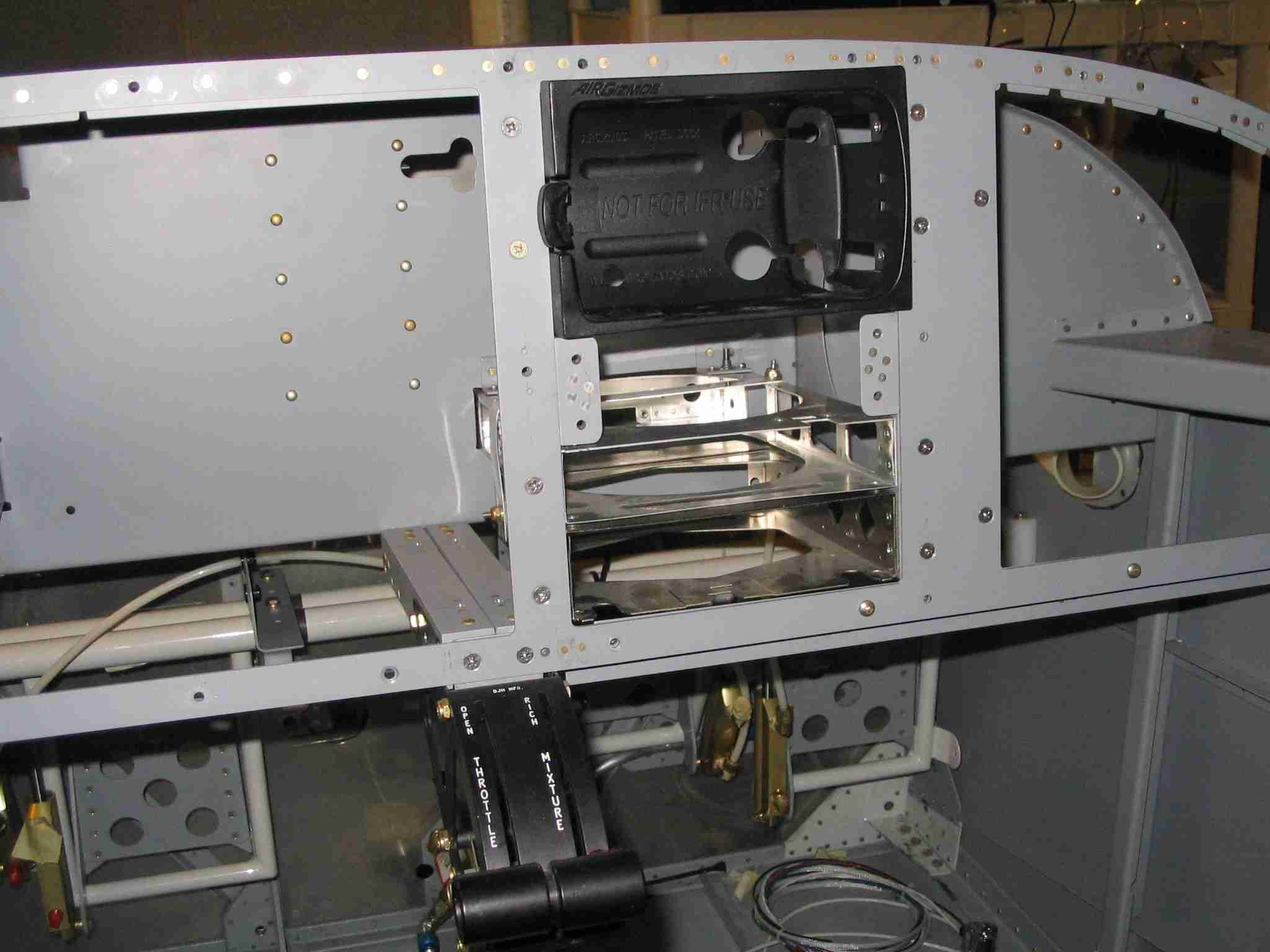
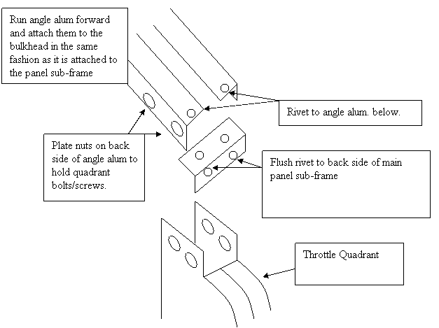
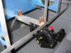
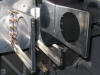
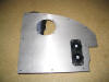
 E
The throttle quadrant attach bracket is coming together. What you
are looking are two pieces of 1" aluminum angle as described above.
I might add plate nuts to hold it in place rather than use rivets.
What I don't know is where I will put the plate nuts. The quadrant
is bolted to the aluminum angle with three AN-3 bolts on each side.
The advantage of using the 1" AA is that I can easily attach a bracket to
hold the throttle cable in place. (8/16/05) E
The throttle quadrant attach bracket is coming together. What you
are looking are two pieces of 1" aluminum angle as described above.
I might add plate nuts to hold it in place rather than use rivets.
What I don't know is where I will put the plate nuts. The quadrant
is bolted to the aluminum angle with three AN-3 bolts on each side.
The advantage of using the 1" AA is that I can easily attach a bracket to
hold the throttle cable in place. (8/16/05) |
| |
|
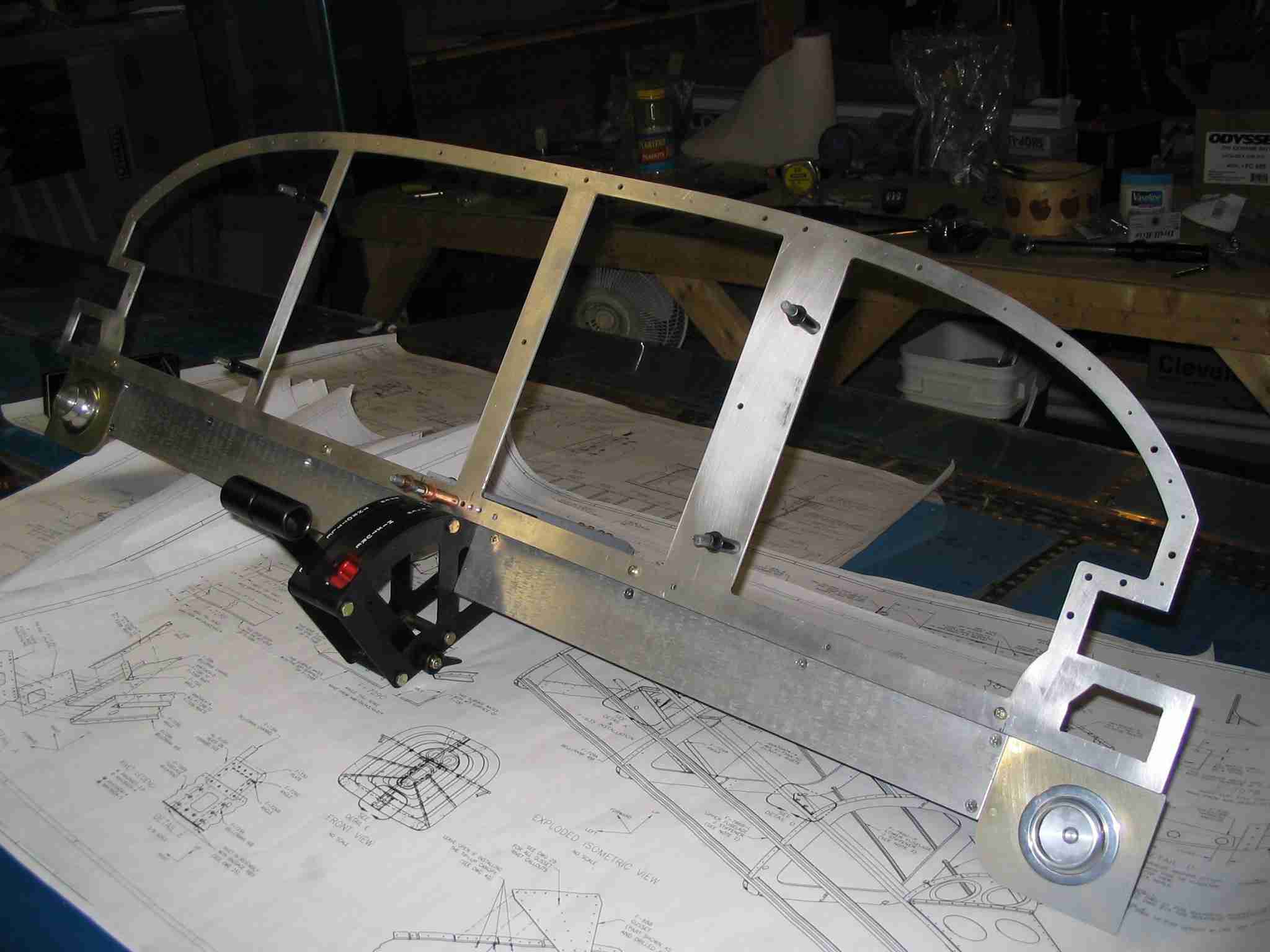
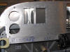
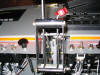
 F
Here is something you don't see on many side-by-side RV's, a center
mounted throttle quadrant. The installation was surprisingly easy
and the cost wasn't out of line. (8/21/05) F
Here is something you don't see on many side-by-side RV's, a center
mounted throttle quadrant. The installation was surprisingly easy
and the cost wasn't out of line. (8/21/05) |
| |
|
 E
This is a close up of the bracket I made out of two 1x1 AA. I'm sure
that is overkill but I wanted it strong enough to hold the brackets I'm
going install to hold the ends of the throttle and mixture cables.
(8/21/05) E
This is a close up of the bracket I made out of two 1x1 AA. I'm sure
that is overkill but I wanted it strong enough to hold the brackets I'm
going install to hold the ends of the throttle and mixture cables.
(8/21/05) |
| |
|
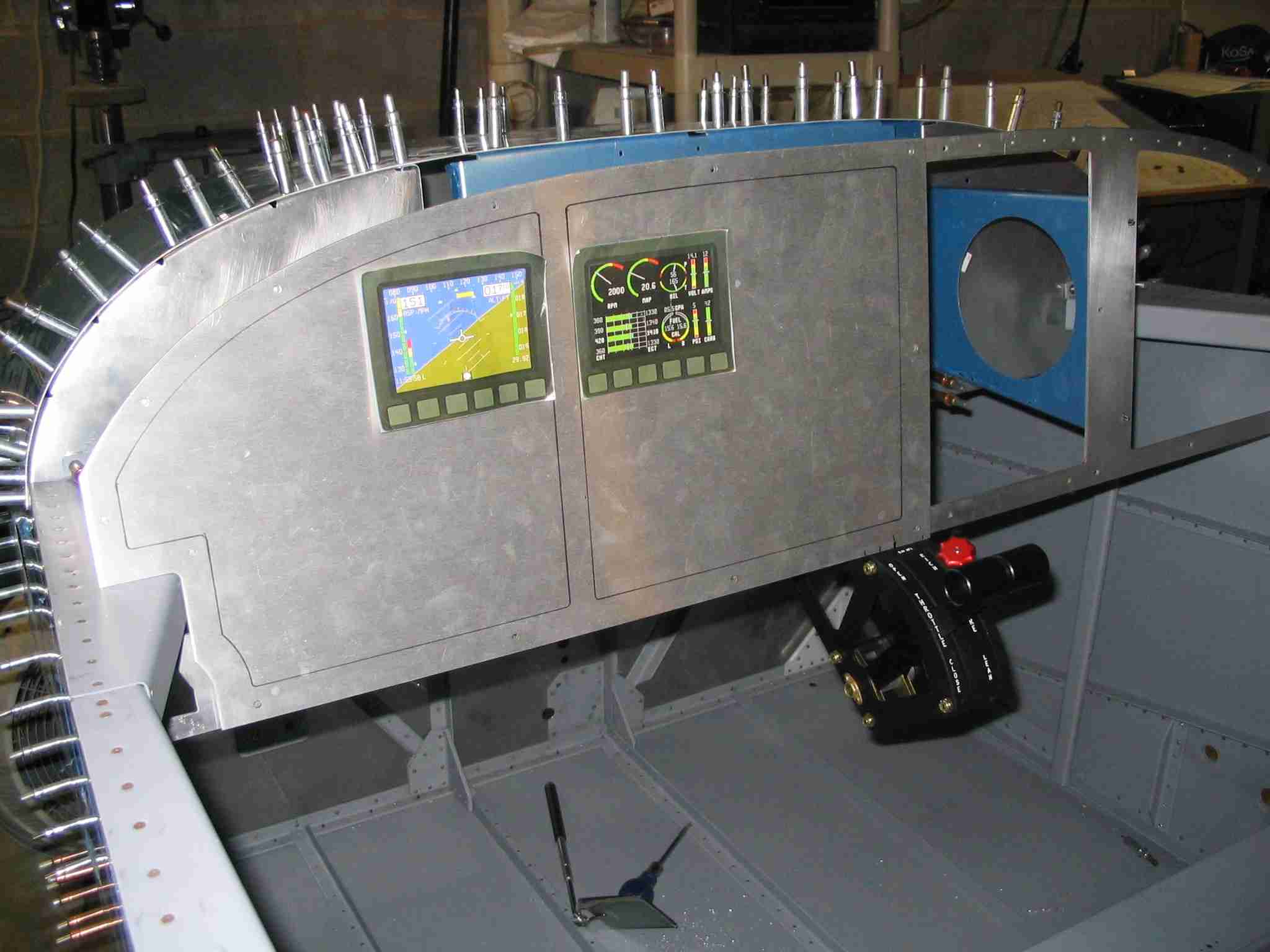
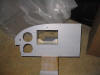
 F
The panel frame is mostly completed at this point. The sub-panels
are ready for drilling of the holes for the switches, if only I knew what those switches
would be. The panel above is going to change. I will probably
install a Dynon D100 7" EFIS on the left side of the panel and move
the Dynon EMS-10 to the right side where it will display the EFIS info and
perform the engine monitoring function in the background. That
should make any right seat passenger-pilots happy.
(10/26/05) F
The panel frame is mostly completed at this point. The sub-panels
are ready for drilling of the holes for the switches, if only I knew what those switches
would be. The panel above is going to change. I will probably
install a Dynon D100 7" EFIS on the left side of the panel and move
the Dynon EMS-10 to the right side where it will display the EFIS info and
perform the engine monitoring function in the background. That
should make any right seat passenger-pilots happy.
(10/26/05) |
| |
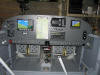
|
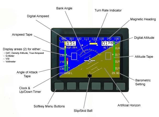
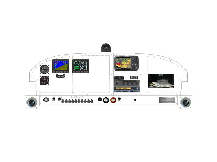
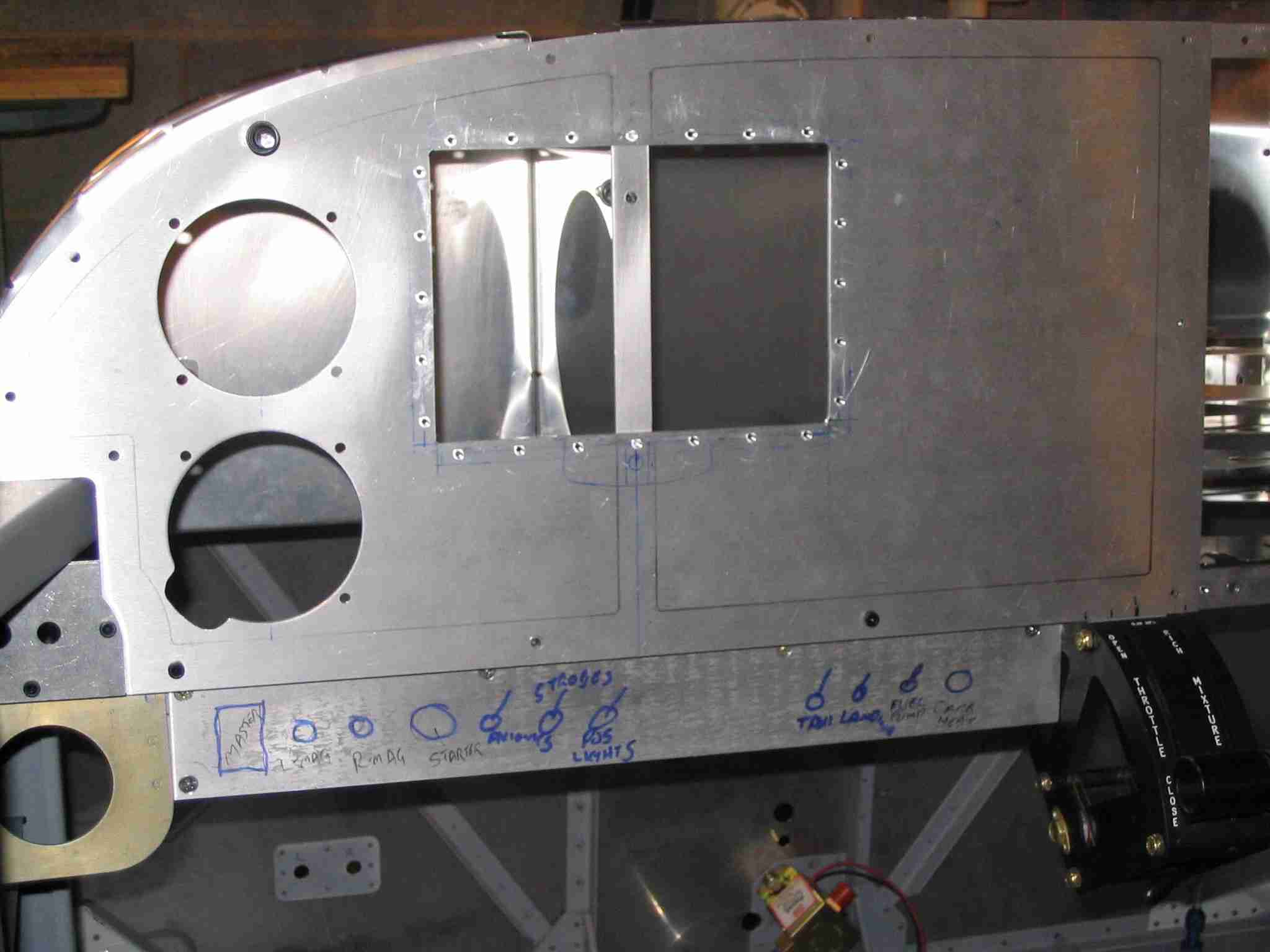
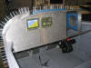
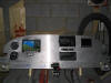
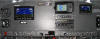
 E
The panel mock up is finished. In the upper left hand corner will be
the airspeed indicator and directly below it the altimeter. Below
the 7" Dynon EFIS will be a slip ball and the radio stack will consist of
a Garmin 296 GPS, intercom, ELT panel, iCom radio, and a transponder.
The sub panel isn't completely thought out yet but from left to right it will
have the master switch, left Pmag switch, right Pmag switch, starter
button, avionics master, strobes, position lights, taxi light, landing,
light, fuel pump, carb heat, throttle, mixture, flaps, interior light
dimmer, and finally circuit breakers. (11/23/05) E
The panel mock up is finished. In the upper left hand corner will be
the airspeed indicator and directly below it the altimeter. Below
the 7" Dynon EFIS will be a slip ball and the radio stack will consist of
a Garmin 296 GPS, intercom, ELT panel, iCom radio, and a transponder.
The sub panel isn't completely thought out yet but from left to right it will
have the master switch, left Pmag switch, right Pmag switch, starter
button, avionics master, strobes, position lights, taxi light, landing,
light, fuel pump, carb heat, throttle, mixture, flaps, interior light
dimmer, and finally circuit breakers. (11/23/05) |
| |
|
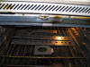
 F
With the change to the Dynon D100 7" EFIS it is now necessary to cut the
F745 panel support rib. As you can see from the picture, the rib
will interfere with the D100 mounting tray. (1/9/06) F
With the change to the Dynon D100 7" EFIS it is now necessary to cut the
F745 panel support rib. As you can see from the picture, the rib
will interfere with the D100 mounting tray. (1/9/06) |
| |
|
  E
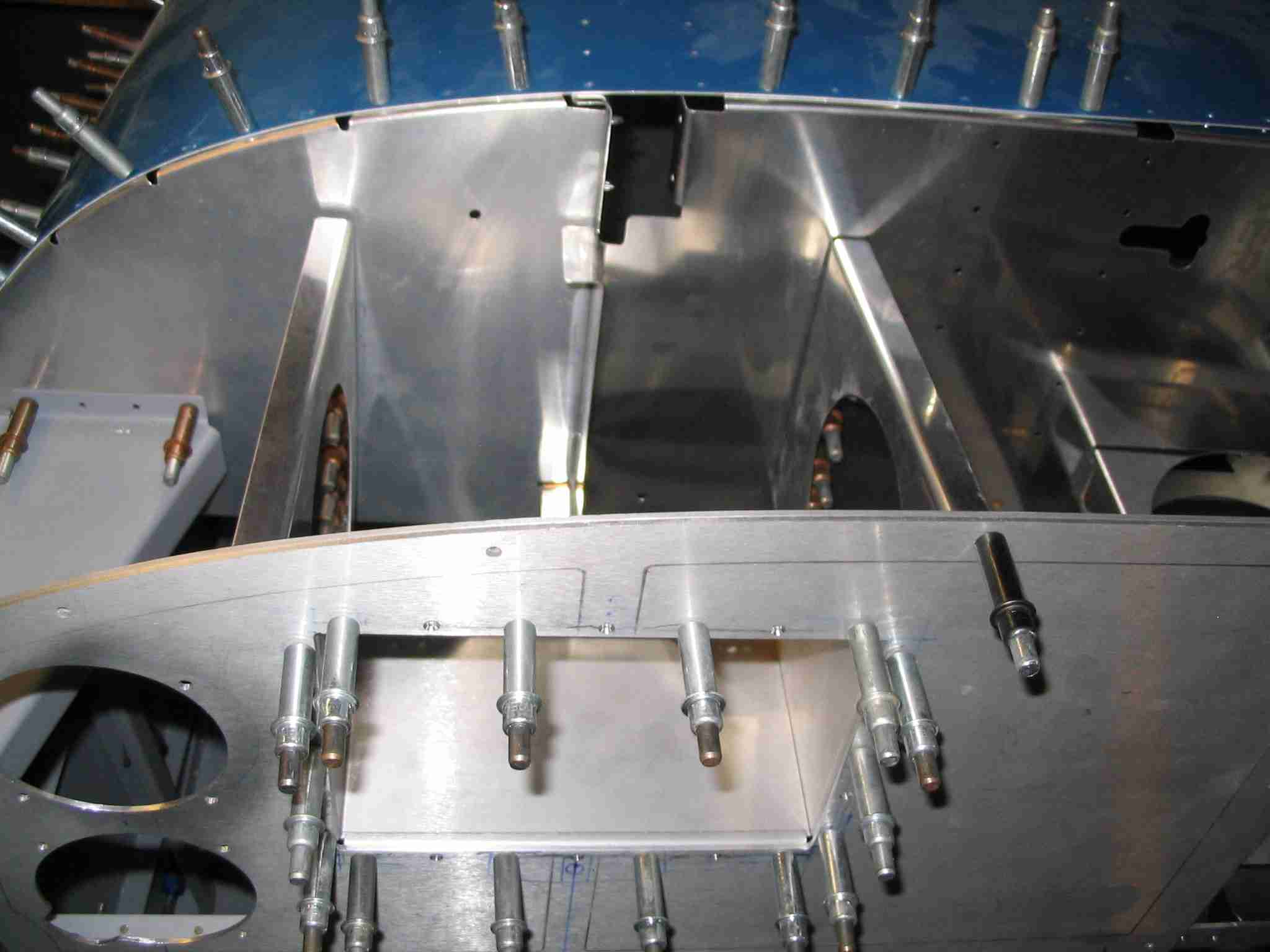
The F745 ribs support the panel and keep it from vibrating. Panel
vibration can reduce the life of the instruments and just make them downright hard to read. My solution was simple, buy two (left and right)
extra ribs from Van's. Cleco them in place and mark where they will
come through the forward sub-panel. Remove them and draw a line
forward of the pre-punched rivet line, cut them, bend up the flange, and
drill them to the forward sub-panel. (1/9/06) E
The F745 ribs support the panel and keep it from vibrating. Panel
vibration can reduce the life of the instruments and just make them downright hard to read. My solution was simple, buy two (left and right)
extra ribs from Van's. Cleco them in place and mark where they will
come through the forward sub-panel. Remove them and draw a line
forward of the pre-punched rivet line, cut them, bend up the flange, and
drill them to the forward sub-panel. (1/9/06) |
| |
|
   F
While I was at it, I put a small flange in the bottom of the original F745
rib to help support the D100 tray. As it turned out, there is enough
room between the D100 tray and the Airspeed and Altimeter, stacked
vertically to the left. (1/9/06) F
While I was at it, I put a small flange in the bottom of the original F745
rib to help support the D100 tray. As it turned out, there is enough
room between the D100 tray and the Airspeed and Altimeter, stacked
vertically to the left. (1/9/06)
Note: During the final installation I eliminated
the right 1/2 rib. This was done after talking to a number of people
who only installed one rib and found the panel was well supported.
As always, your mileage may very. |
| |
|
 E
The panel is starting to come together. The Dynon D100 still needs
to be purchased, two red post lights are on order to illuminate the two
analog instruments (airspeed and altimeter), an appropriate "fuel pump on"
light needs to be located, and finally the electrical switches along the
bottom have to be fitted. (1/14/06) E
The panel is starting to come together. The Dynon D100 still needs
to be purchased, two red post lights are on order to illuminate the two
analog instruments (airspeed and altimeter), an appropriate "fuel pump on"
light needs to be located, and finally the electrical switches along the
bottom have to be fitted. (1/14/06) |
| |
|
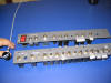
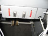
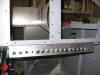  F
More progress on the panel. Both the left and right sub-panels are
drilled for the various switches and circuit breakers. (2/26/06) F
More progress on the panel. Both the left and right sub-panels are
drilled for the various switches and circuit breakers. (2/26/06) |
| |
|
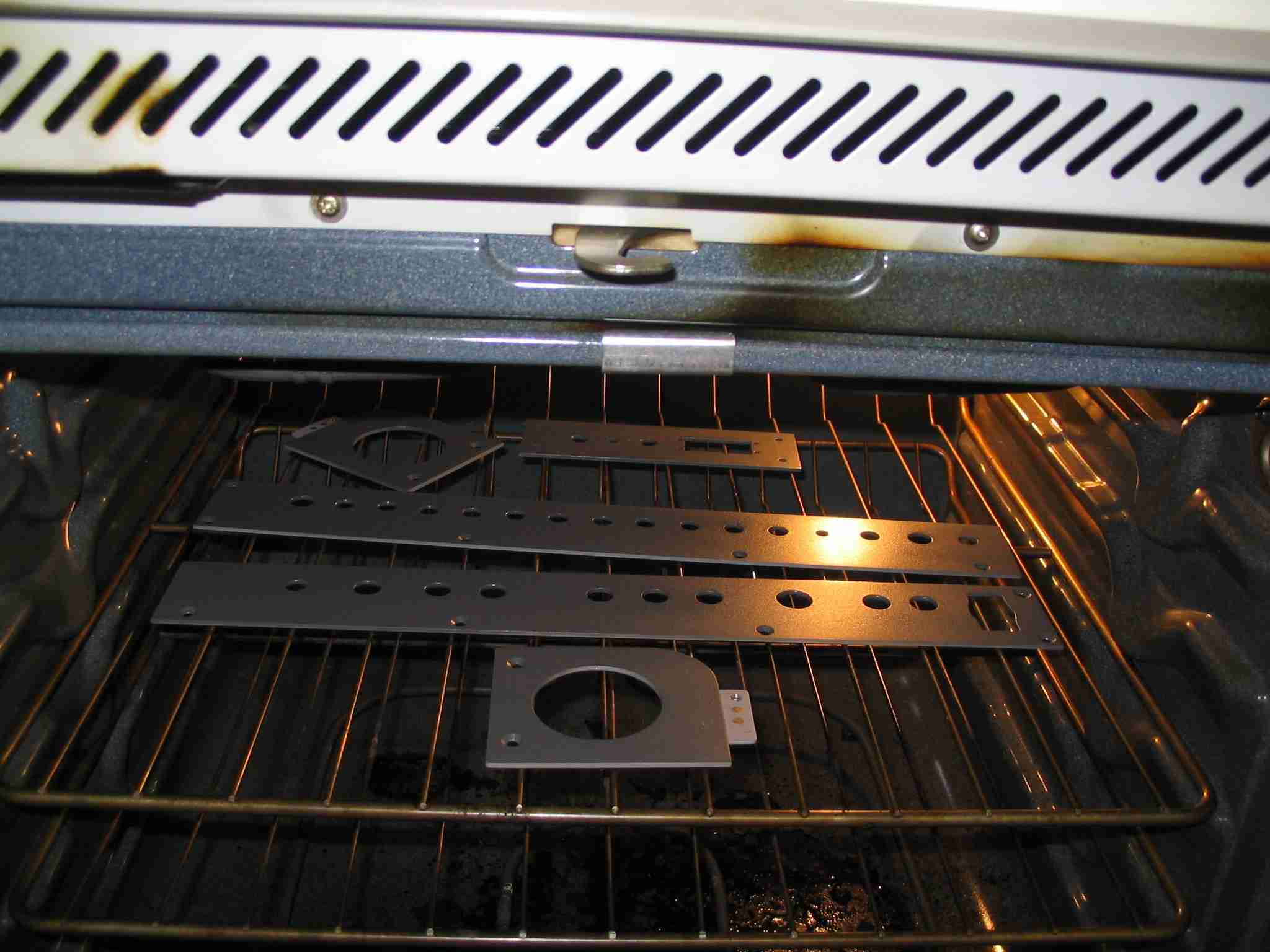
 E
After painting the instrument sub-panels I baked them in the oven for two
hours at 200 degrees F. This was done to harden the paint and
hopefully keep it from scratching. (2/27/06) E
After painting the instrument sub-panels I baked them in the oven for two
hours at 200 degrees F. This was done to harden the paint and
hopefully keep it from scratching. (2/27/06) |
| |
|
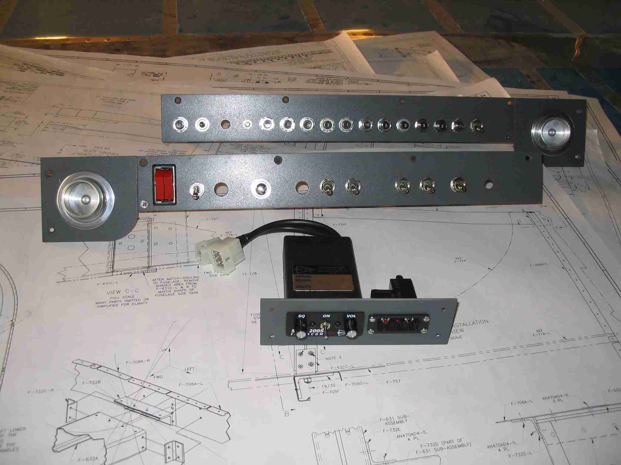
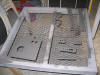
 F
Here are the sub-panels, vent panels and intercom/ELT panel all ready to
install. What looks like a scratch by the left vent is dust.
After viewing this picture I thought I was going to have repaint the thing
but it brushed right off, thank goodness. (2/28/06) F
Here are the sub-panels, vent panels and intercom/ELT panel all ready to
install. What looks like a scratch by the left vent is dust.
After viewing this picture I thought I was going to have repaint the thing
but it brushed right off, thank goodness. (2/28/06) |
| |
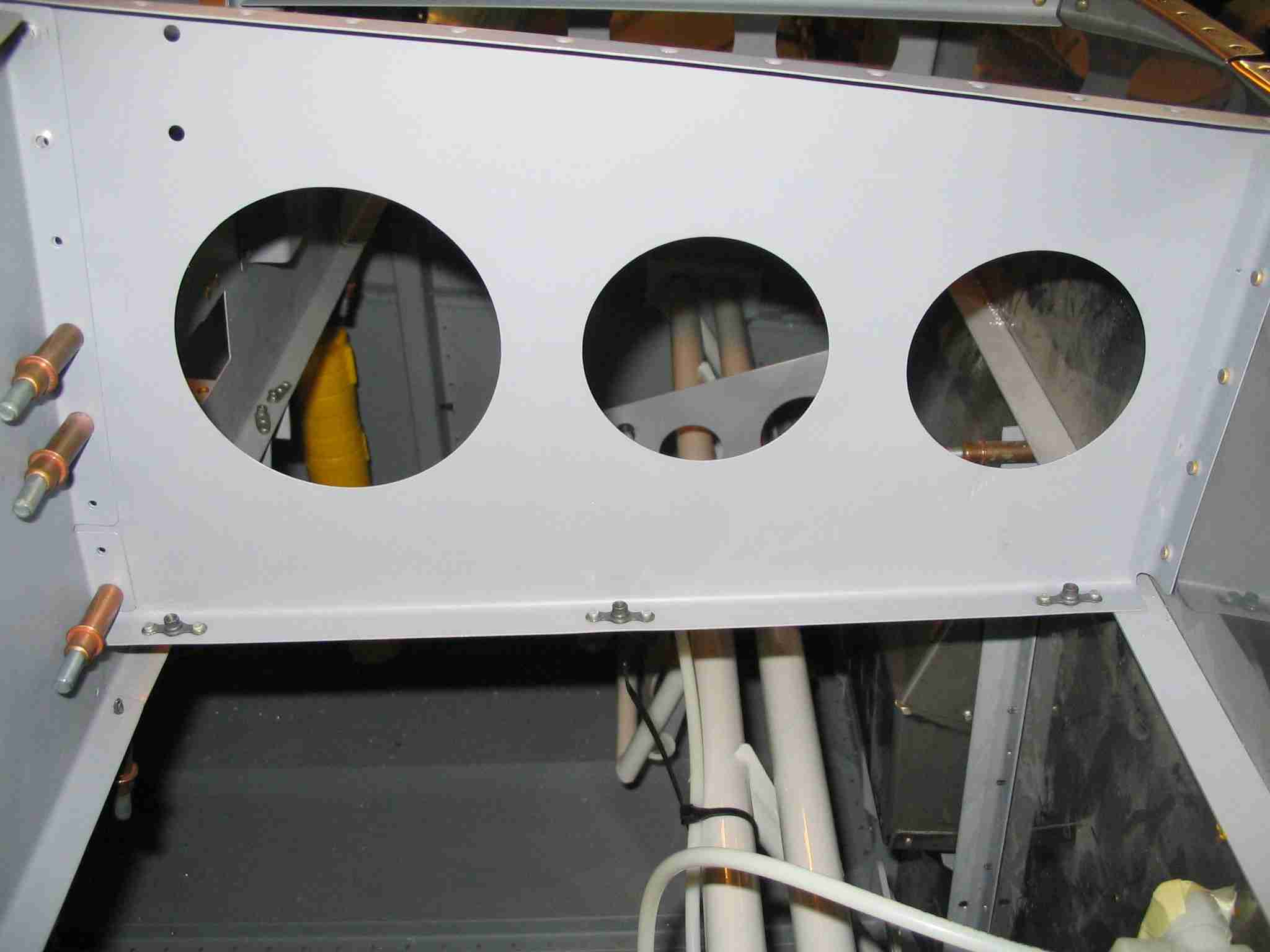
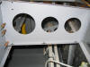
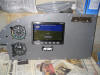
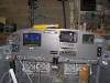
|
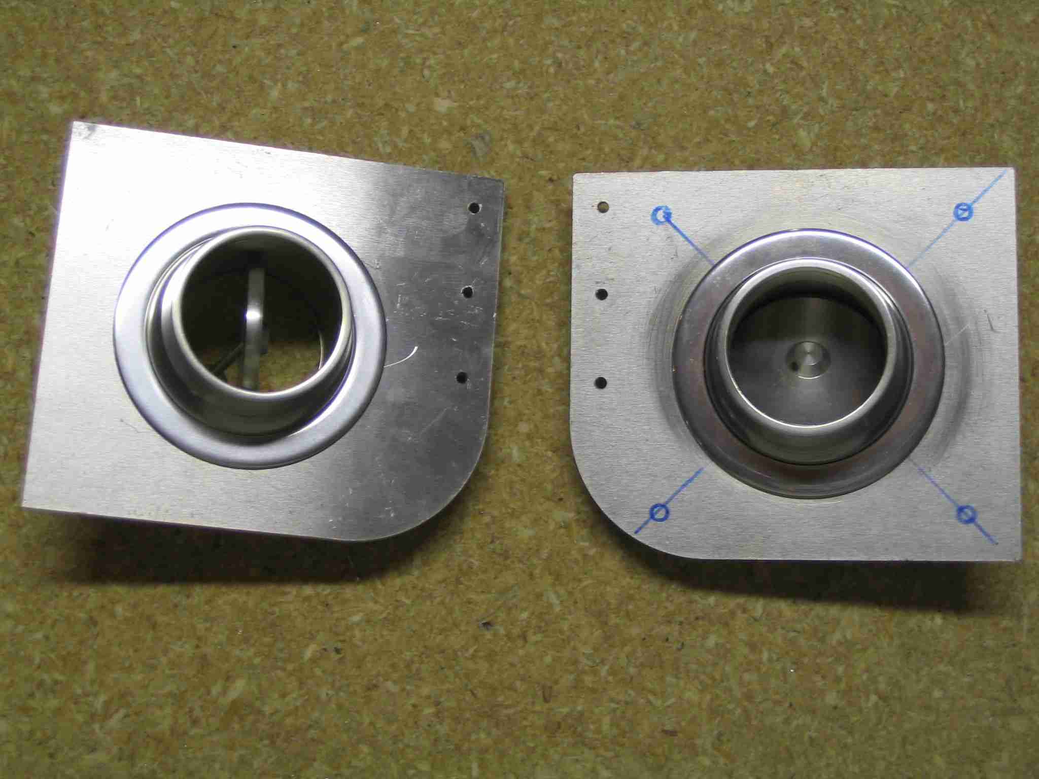
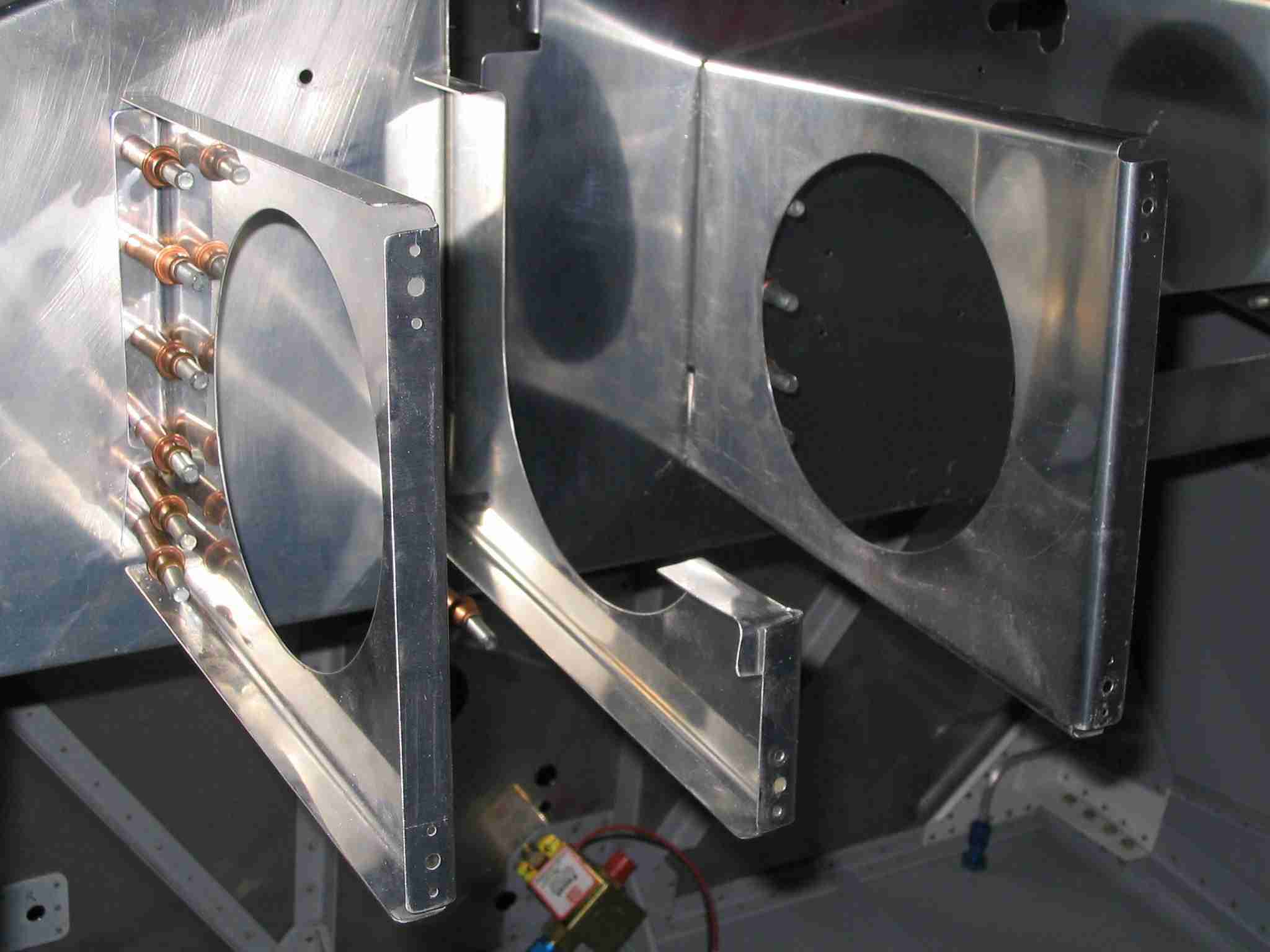
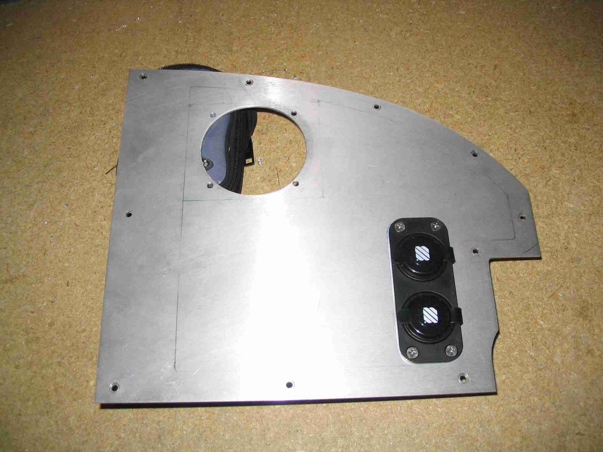
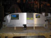
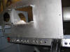
 E
This is the right side of the instrument panel. The hole will be filled by a Dynon D10
Engine Monitoring System (EMS) and the duel power ports will be used for
powering hand held devices of some type or another. The upper plug
will be connect to the "always hot" electrical bus with heavier wire and a
7 1/2 amp fuse so that I can plug in a battery minder to keep things
charged. The lower plug will be connected to the avionics bus and
will be turned on with the Avionics Master switch. The duel plug
unit was procured at the local West Marine store. More detailed
pictures of these plugs can be found on the 2/11/06 entry of the
Electrical System
page. (3/25/06) E
This is the right side of the instrument panel. The hole will be filled by a Dynon D10
Engine Monitoring System (EMS) and the duel power ports will be used for
powering hand held devices of some type or another. The upper plug
will be connect to the "always hot" electrical bus with heavier wire and a
7 1/2 amp fuse so that I can plug in a battery minder to keep things
charged. The lower plug will be connected to the avionics bus and
will be turned on with the Avionics Master switch. The duel plug
unit was procured at the local West Marine store. More detailed
pictures of these plugs can be found on the 2/11/06 entry of the
Electrical System
page. (3/25/06) |
| |
|
  F
The panel is starting to come together. The final (3rd) coat of
paint has been applied to the right panel, sub panels, vent panels,
intercom/ELT panel, etc. The left panel has been primed and will
three coats of paint, then it is back in the oven for everything.
When the pictures where taken on 2/27/06 the parts only had one coat of
paint. Since then, the parts have been wet sanded with 600 grit
paper between coats. This is in an effort to make them more durable. (3/31/06) F
The panel is starting to come together. The final (3rd) coat of
paint has been applied to the right panel, sub panels, vent panels,
intercom/ELT panel, etc. The left panel has been primed and will
three coats of paint, then it is back in the oven for everything.
When the pictures where taken on 2/27/06 the parts only had one coat of
paint. Since then, the parts have been wet sanded with 600 grit
paper between coats. This is in an effort to make them more durable. (3/31/06) |
| |
|
  E
Now that I am getting close to running wires the question of where to run
them has raised its ugly head. The solution was not so ugly. I
put plate nuts on the bottom of the forward ribs and will use adel clamps
to old the wires. This eliminates the need to drill holes through
the ribs and will facilitate adding wires in the future. I wish I
could take credit for that idea but I can't, my friend Radomir suggested
it. Thanks Rad! (3/31/06) E
Now that I am getting close to running wires the question of where to run
them has raised its ugly head. The solution was not so ugly. I
put plate nuts on the bottom of the forward ribs and will use adel clamps
to old the wires. This eliminates the need to drill holes through
the ribs and will facilitate adding wires in the future. I wish I
could take credit for that idea but I can't, my friend Radomir suggested
it. Thanks Rad! (3/31/06) |
| |
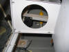
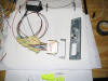
|
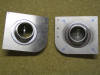
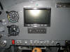
  F
With luck the radio trays are in to stay. The black thing at the top
is an AirGizmo and will hold the Gramin 396 GPS that I will own, some day.
The space below that will hold the intercom and ELT. Below that is
the iCom radio followed by the Garmin transponder. That rounds out
my "extensive" avionics suite. Note all the plate nuts, this is to
help with any future maintenance issues. If you look at the picture
on the right you will notice the radio is supported with two pieces of
angle aluminum and plate nuts. This was done so that a screwdriver
can be inserted from the bottom of the radio tray to make the removal of
the tray easier. (3/31/06) F
With luck the radio trays are in to stay. The black thing at the top
is an AirGizmo and will hold the Gramin 396 GPS that I will own, some day.
The space below that will hold the intercom and ELT. Below that is
the iCom radio followed by the Garmin transponder. That rounds out
my "extensive" avionics suite. Note all the plate nuts, this is to
help with any future maintenance issues. If you look at the picture
on the right you will notice the radio is supported with two pieces of
angle aluminum and plate nuts. This was done so that a screwdriver
can be inserted from the bottom of the radio tray to make the removal of
the tray easier. (3/31/06) |
| |
|
 E
How's that for a "moving map" display? It will move with me anywhere
I go. The clip came from the aviation department at Wal-Mart and
cost all of $.99. Of course I had to take the clipboard it was
attached to home with me as well. E
How's that for a "moving map" display? It will move with me anywhere
I go. The clip came from the aviation department at Wal-Mart and
cost all of $.99. Of course I had to take the clipboard it was
attached to home with me as well.
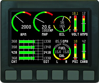
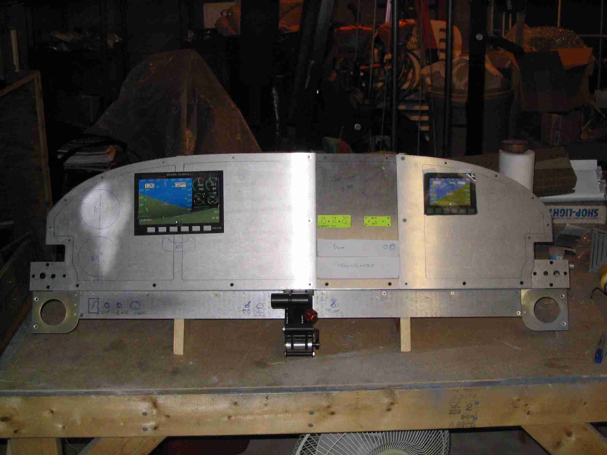
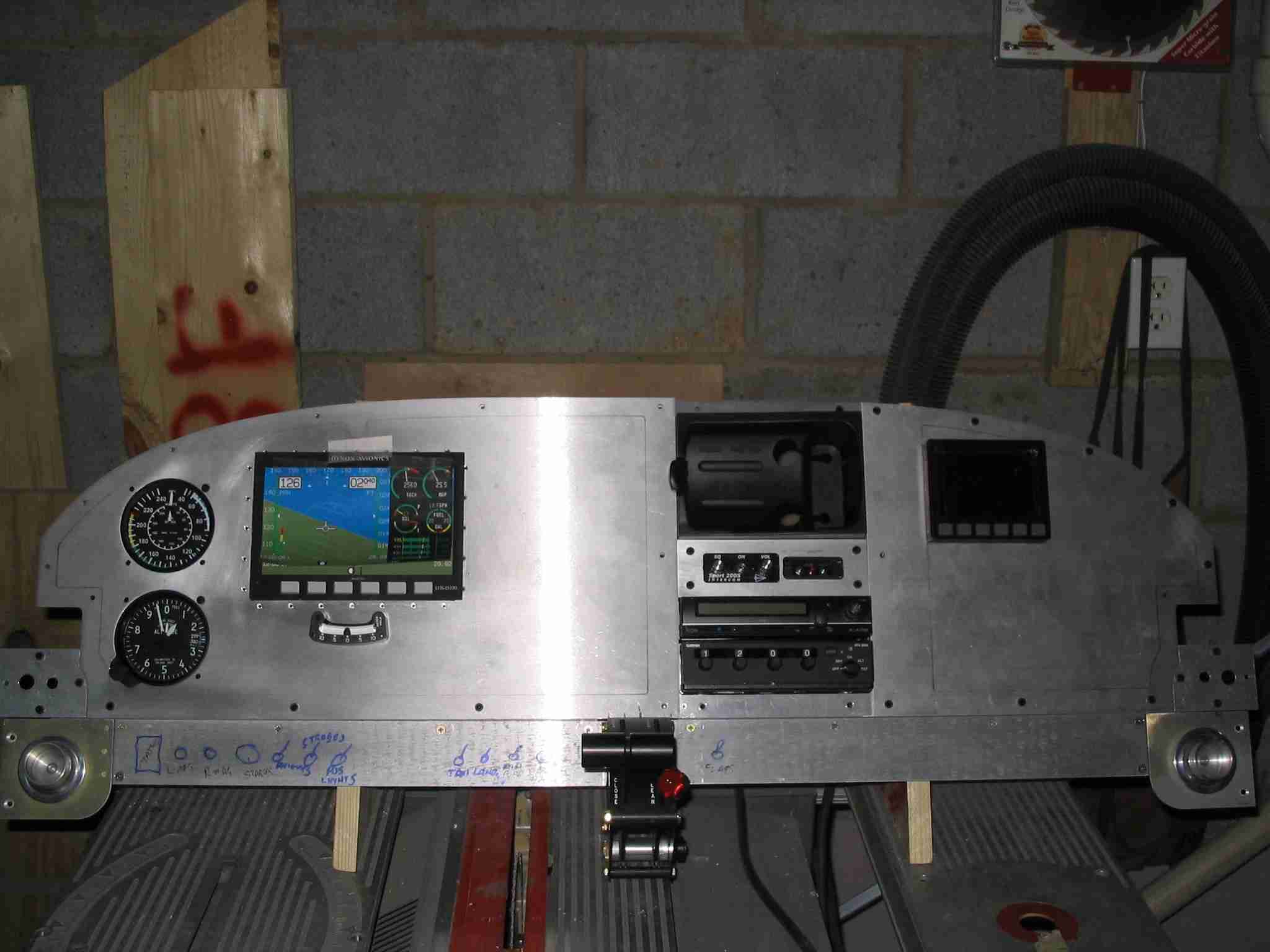
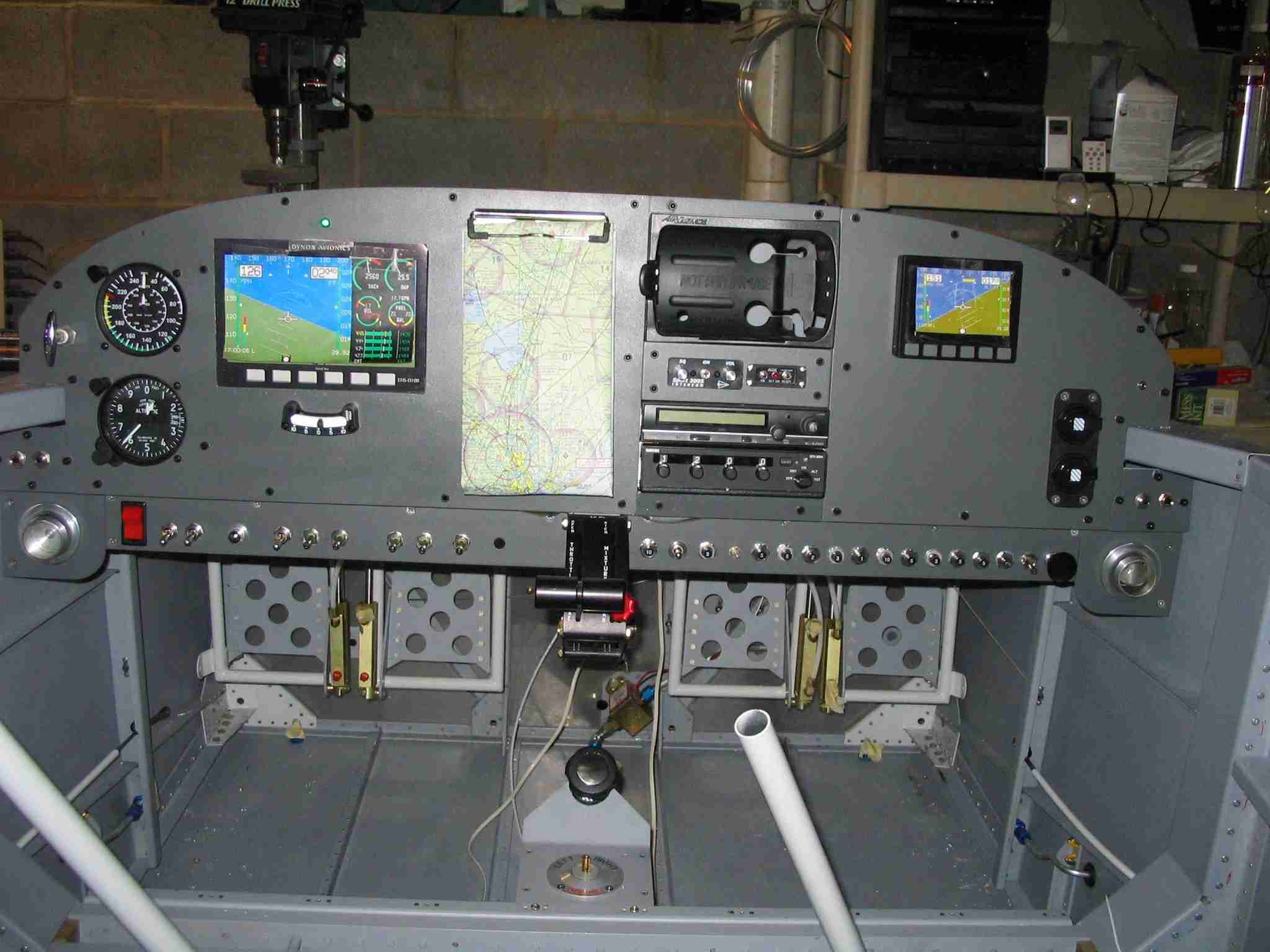
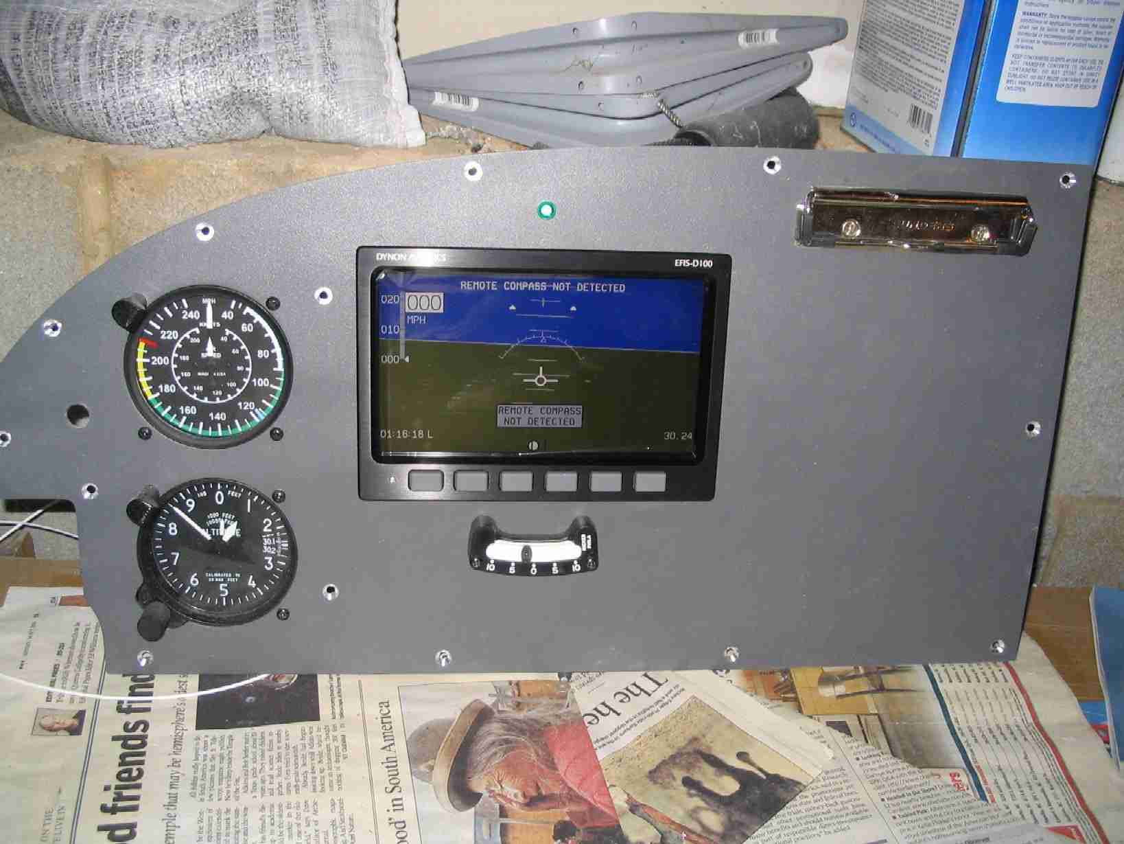
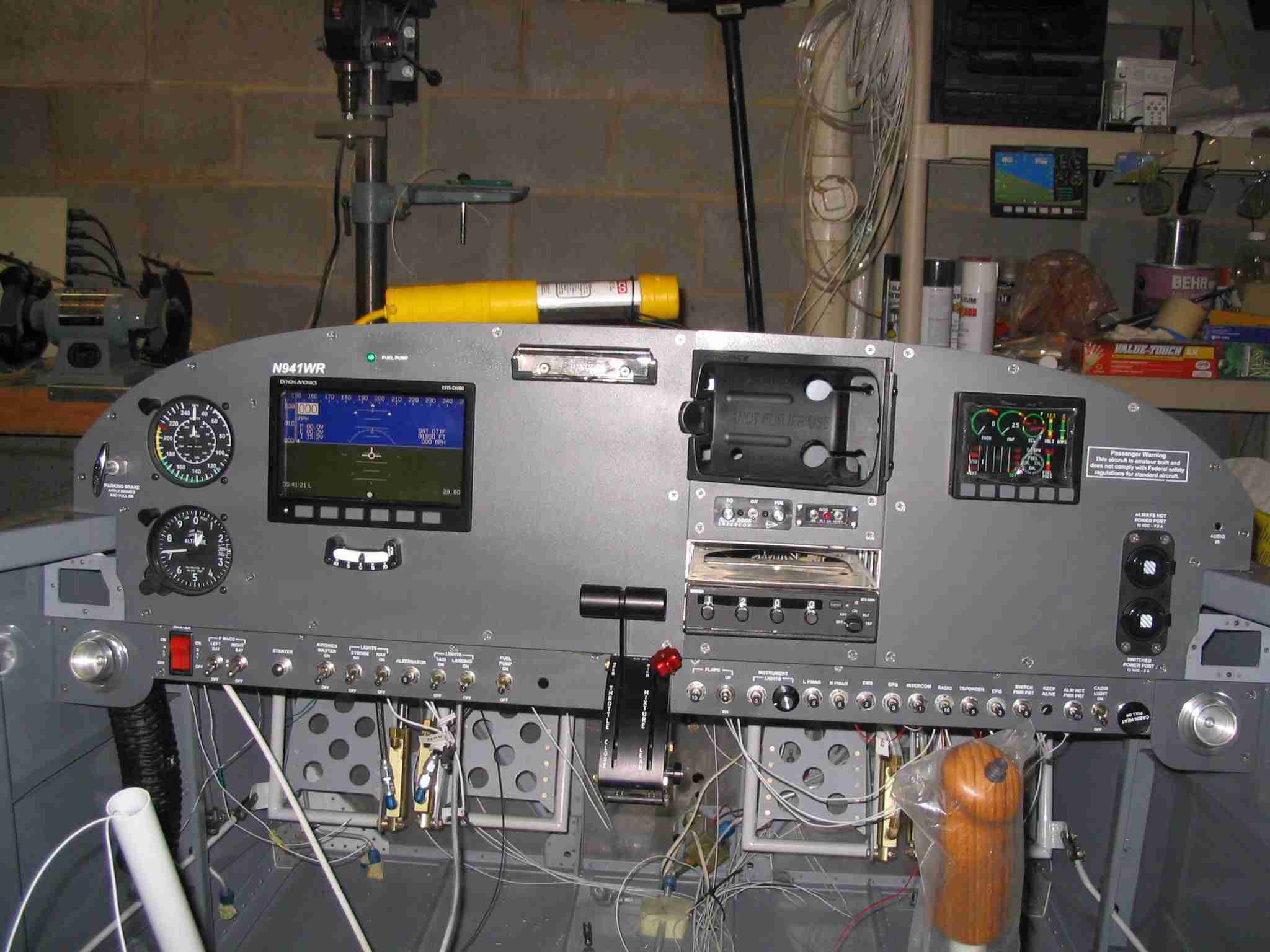
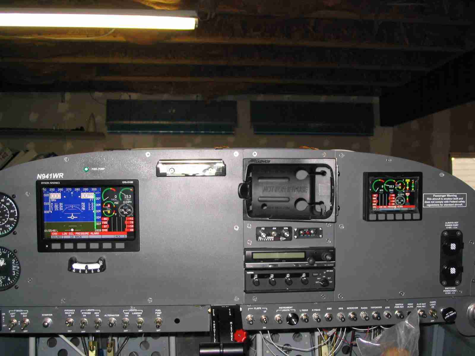
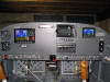
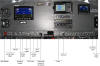
All
11 pieces of the panel are cut, painted and fitted. I hope not to
have to remove them again but I know that won't be the case. The two
Dynon screen displays are nothing more than marketing cutouts. The
tray for the
Dynon D100 EFIS is installed on the left side but I have yet to buy
the thing. The
Dynon EMS D10 is there but covered by the display cutout so I can get
an idea how everything will look.
Dynon
has promised that the two units are able to be bussed together so they can
display information from the other unit. Notice how the unit on the
left is displaying the engine parameters and the engine monitor on the
right is displaying flight information.
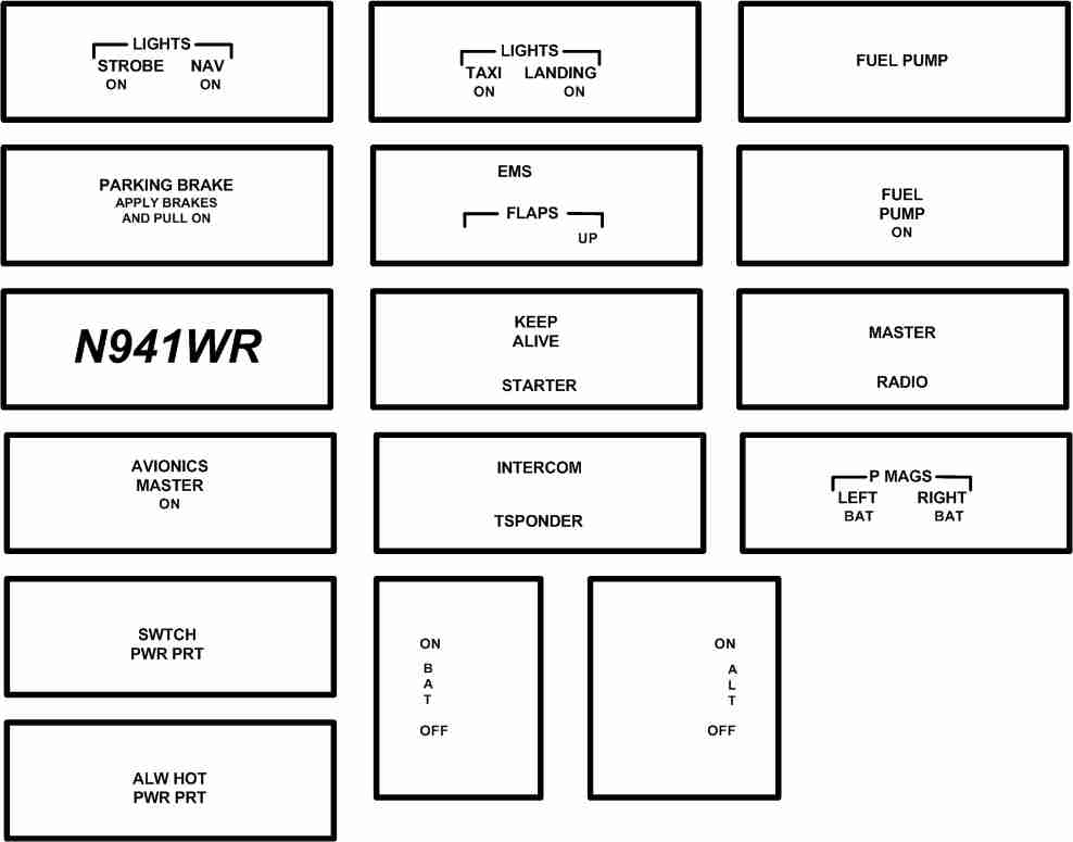
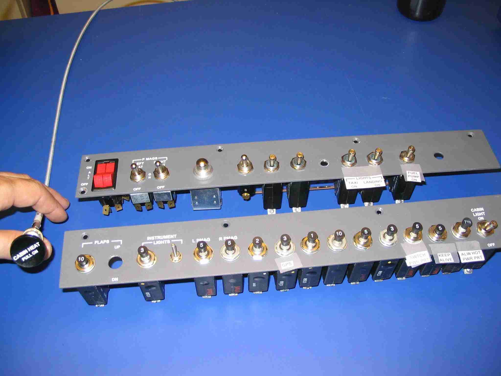
Switches and Controls from left to right:
Parking brake (Upper left, by the airspeed
indicator)
Headset jacks
Master switch
Left Pmag
Right Pmag
Starter button
Avionics master
Strobes
Position lights
Taxi light
Landing light
Fuel boost pump
Carburetor heat (Empty hole)
Throttle
Mixture
Flap circuit breaker
Flap Switch (Up to raise flaps, down to
lower flaps.)
Interior light circuit breaker (red)
Interior light dimmer (red)
Left Pmag circuit breaker (5A)
Right Pmag circuit breaker (5A)
Dynon EMS D10 circuit breaker (2A)
Garmin 396 handheld GPS circuit breaker
(3A)
Intercom circuit breaker (1A)
Communications radio circuit breaker (10A)
Transponder circuit breaker (5A)
Dynon EFIS D100 circuit breaker (3A)
Switched power port circuit breaker (5A)
Electronics keep alive circuit breaker
(5A)
Always hot power port circuit breaker (7
1/2A - Will be used with a "battery minder".)
Cockpit courtesy light (white)
Cabin heat
Stereo input jack (Above and to the right
of the two power ports)
If you noticed that not all the circuits have a
breaker, that is because some of the switches are "circuit breaker
switches" and do not require an independent breaker.
The instrument panel was painted with three coats
of Pewter Rust-Oleum Textured, Fine Textured Finish (yes, it is spray
paint) found in the aviation section of my local Home Depot. The
panel was wet sanded with 600 grit wet/dry sand paper between coats and
baked in the oven for two hours at 200o F.
(4/3/06) |
| |
|
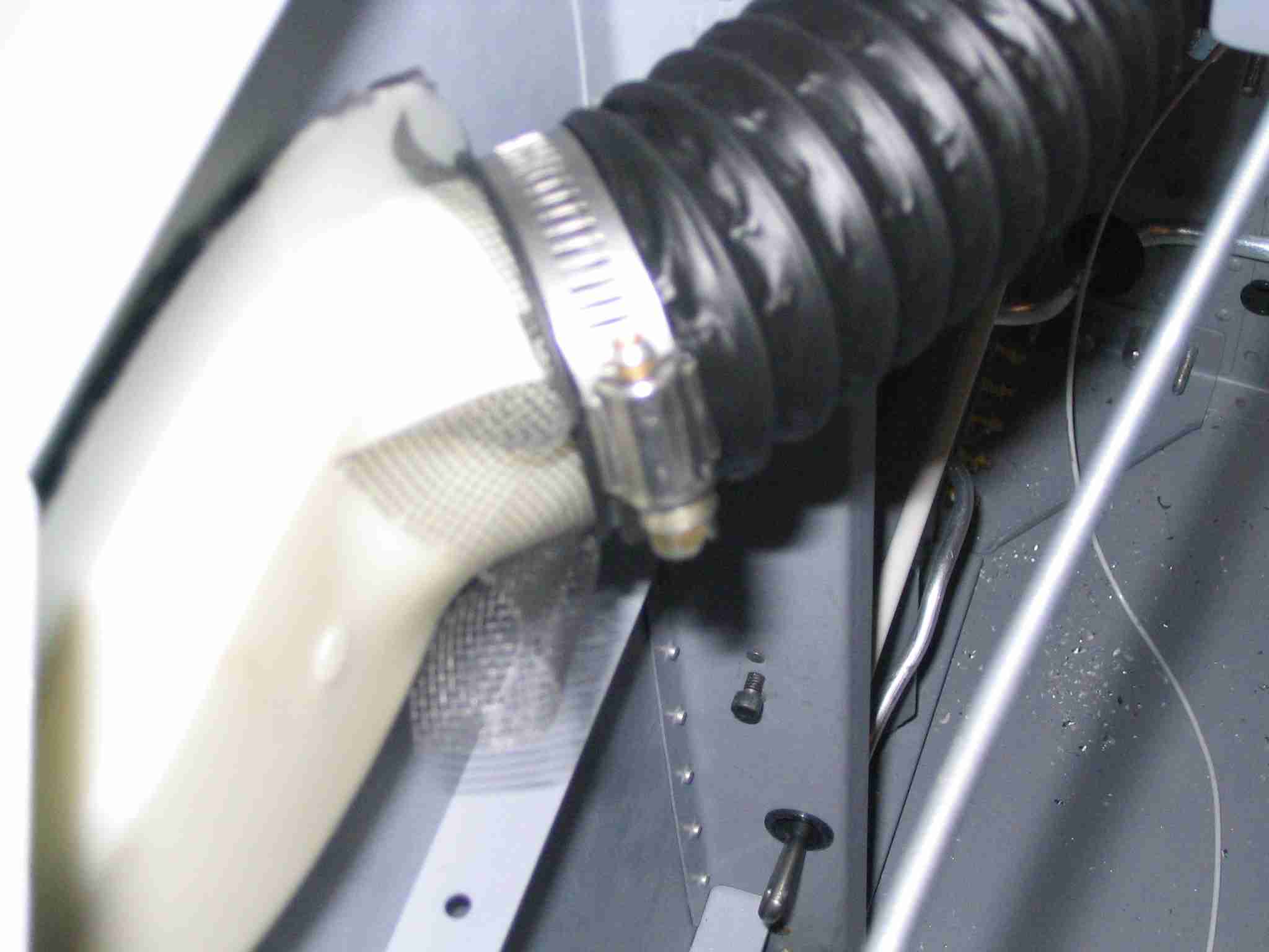
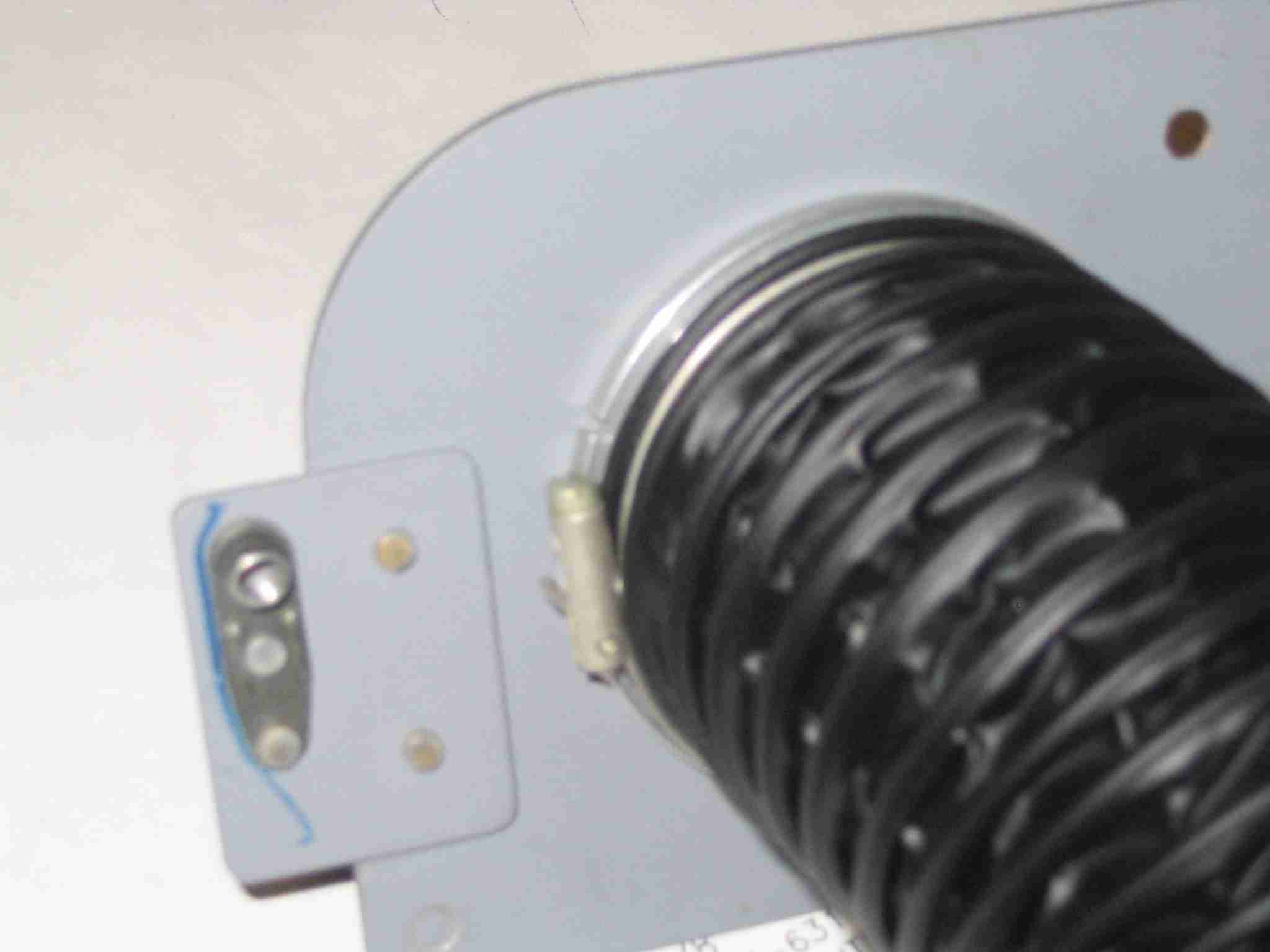
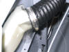 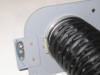 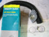 F
The vent ducts are now installed. Due to the limited grip length of
the Gasper vents I'm installing I had to buy some air hose ducting from
Car Quest. You will notice on the box that it is made for Van's and
RV's so I figure it will work. When you look at the picture you will
also see the wire clamp that came with the vent, this worked great.
The third picture illustrates out how I clamped a piece of screen at the
NACA duct using an automotive hose clamp. When doing this make sure
the screw will be accessible once the top skin is riveted in place. (4/11/06) F
The vent ducts are now installed. Due to the limited grip length of
the Gasper vents I'm installing I had to buy some air hose ducting from
Car Quest. You will notice on the box that it is made for Van's and
RV's so I figure it will work. When you look at the picture you will
also see the wire clamp that came with the vent, this worked great.
The third picture illustrates out how I clamped a piece of screen at the
NACA duct using an automotive hose clamp. When doing this make sure
the screw will be accessible once the top skin is riveted in place. (4/11/06) |
| |
|
 E
For my birthday my lovely wife gave me a
DecalPRO. This will be used to create all the labels for my
instrument panel. In the end you wind up with decals that are
similar to those used for plastic models. You know, like the ones we
all built when we were kids. The picture on the left is the draft of
some of the labels I think will be required. Note the dark black box
around each label, this is essential to making good labels. (6/30/06
& Updated on 8/13/06) E
For my birthday my lovely wife gave me a
DecalPRO. This will be used to create all the labels for my
instrument panel. In the end you wind up with decals that are
similar to those used for plastic models. You know, like the ones we
all built when we were kids. The picture on the left is the draft of
some of the labels I think will be required. Note the dark black box
around each label, this is essential to making good labels. (6/30/06
& Updated on 8/13/06) |
| |
|
 F
The D100 arrived from
Affordable
Panels. Man, this thing is soooo cool! Since I had
previously ordered the bracket and had riveted it into the panel all I had
to do was slide it in, tighten one Allen screw and turn it on. It
arrived with the internal battery fully charged so I could tip and rotate
it. Once the canopy is finished I will jump on the wiring and get
this thing put in its final resting place. (7/14/06) F
The D100 arrived from
Affordable
Panels. Man, this thing is soooo cool! Since I had
previously ordered the bracket and had riveted it into the panel all I had
to do was slide it in, tighten one Allen screw and turn it on. It
arrived with the internal battery fully charged so I could tip and rotate
it. Once the canopy is finished I will jump on the wiring and get
this thing put in its final resting place. (7/14/06) |
| |
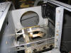
|
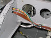  E
Now comes the fun stuff. With the panel fitted I installed the two
wiring harnesses required for the Dynon D10 EMS (Engine Monitoring
System). The bottom harness goes through the firewall and attaches
to the EGT's and Cylinder Head temperature probes. The top harness
controls everything else. The wires hanging down in the left picture
is for updating the EMS via computer. Once Dynon releases their
upcoming upgrade, I will install the new software on both this unit and
the D100 EFIS. That should happen by the end of next month.
The third picture is with both Dynon's powered up for the first time.
(8/6/06) E
Now comes the fun stuff. With the panel fitted I installed the two
wiring harnesses required for the Dynon D10 EMS (Engine Monitoring
System). The bottom harness goes through the firewall and attaches
to the EGT's and Cylinder Head temperature probes. The top harness
controls everything else. The wires hanging down in the left picture
is for updating the EMS via computer. Once Dynon releases their
upcoming upgrade, I will install the new software on both this unit and
the D100 EFIS. That should happen by the end of next month.
The third picture is with both Dynon's powered up for the first time.
(8/6/06) |
| |
|
 F
Here is a sample of some of the panel labels I made with the
DecalPRO. The process is complex and time consuming
but the results are outstanding! I almost gave up but I'm thrilled I
did not. Here are the steps I used to help make these quality
labels: F
Here is a sample of some of the panel labels I made with the
DecalPRO. The process is complex and time consuming
but the results are outstanding! I almost gave up but I'm thrilled I
did not. Here are the steps I used to help make these quality
labels: 1) Draw/type up the labels and
put a BIG black box around them, leaving enough room between the actual
label and the inside edge of the box so you can handle them w/o touching
the label once the box is cut off. (Yes, the sample I posted earlier
was redone with boxes.) 2) Print four
copies of your label sheet on the laser printer using standard white paper
to warm it up and then follow those copies immediately with one copy on
the special blue carrier paper.
3) Cut
out one label from the blue carrier paper and dry it with a heat gun w/o
touching the text. 4) Run the label
through the laminator with the color foil of your choice. Use the
hard plastic board provided in the kit for backing.
5) Peal the color foil back.
6) Use the white tape provided in the kit to lift
off any color that is filling the "O"s, etc. from the label. Again,
do not touch the label with your fingers. (The laminator melts the
plastic color into the black laser toner and any place where there is
moisture on the blue carrier paper. The tape will lift off any
excess color that is not stuck to blue carrier board.)
7) On a clean paper towel, put a piece of the
clear transfer down. Either side up, it doesn't matter.
8) Squirt some Goof Off on it and rub it clean
with another paper towel. The trick here is to build up a good
static charge on the foil so press hard and rub fast, in one direction.
9) Put the clear plastic Mylar over the label,
place it on the hard plastic backing board and run the label through the
laminator. This will cause your colorized text to adhere to the
Mylar. The text is held in place with static electricity and a
little bit of melted Mylar. What I'm trying to say is the label is
very fragile at this point so try to be gentle with it.
10) Drop the label with the clear plastic still
attached into the water bath w/ minimum disturbance to the water.
11) Leave the label alone until the plastic
floats away from the blue paper. Once the Mylar floats free, dip it
in the water bath a few times to clean off any excess glue.
12) Blot, do not rub, the label dry using new,
clean paper towels. 13) Using a cutting
board, not scissors, cut the boarders away from the label. I do this
with the label side of the Mylar up so as not to rub off any of the
letters. 14) Put a paper towel down,
lightly spray it with the glue provided (and I mean lightly!), and stick
the label to the paper towel, letter side up. You shouldn't be able
to read the label as you should be looking at the back of it.
15) Clean your panel with rubbing alcohol and let
it dry. 16) Give the label three quick
blasts of the glue from 12" away. Give your panel one to two quick
squirts. Do not saturate either. More glue is not better, in
fact it will make things worse.
17)
Apply the label, pushing it down with the tip of a tea spoon or some such
instrument. 18) Lift the clear plastic
away from the label. 19) Stand back and
admire your label!
If the label is
messed up, not where you want it, etc. stick some blue 3M painters tape
over the label and lift it off.
There
are a lot of steps to this process and you can trash the label at any
phase so take your time. (8/11/06) |
| |
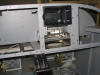
|
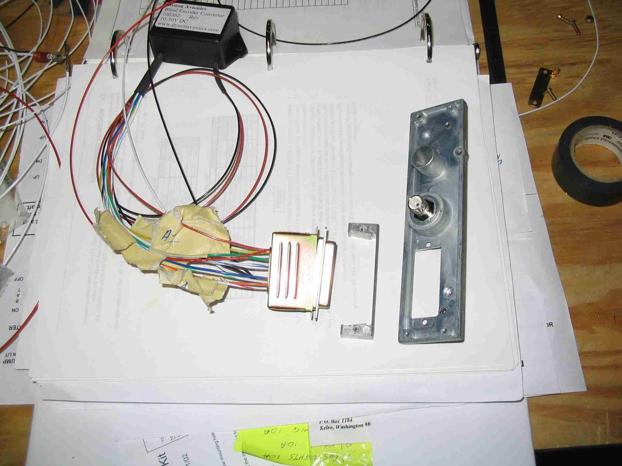
  E
Man cannot live by label making alone. So between sessions of
learning to make those labels I was in the basement wiring up my Garmin
320A transponder and the Dynon altitude reporting thing. Man, there
are a lot of wires going to the transponder. This picture shows the
D-Sub nut plate provided by Gramin, which is the wrong one. The
replacement should arrive in a day or two. The picture on the left
is where I elected to mount the thing. Plate nuts and cap screws are
my friend. Where ever possible I use cap screws and plate nuts
because they are so easy to remove and install when laying on your back
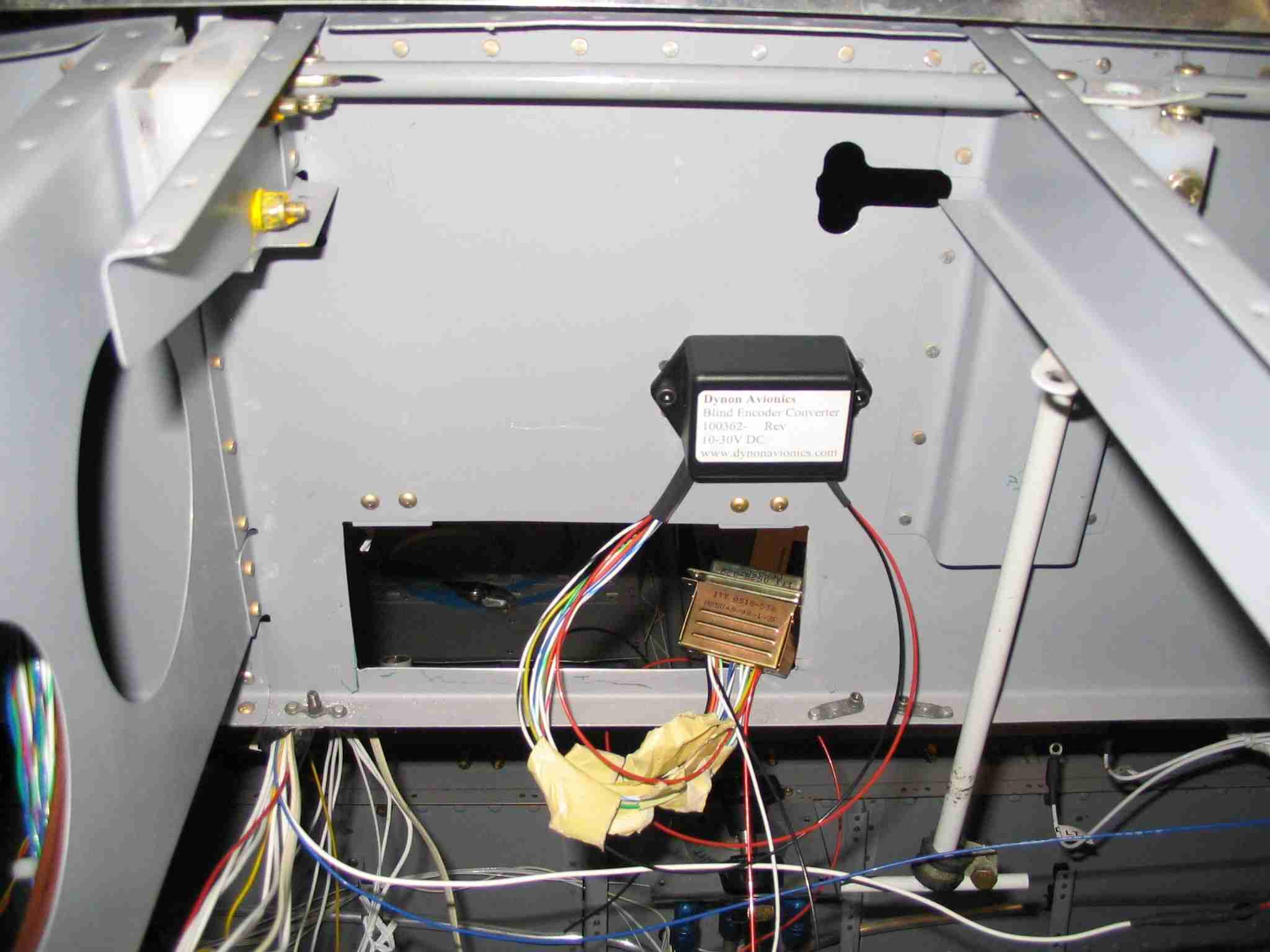
under the panel. Much easier than pan head screws and a Phillips
screw driver! (8/11/06) E
Man cannot live by label making alone. So between sessions of
learning to make those labels I was in the basement wiring up my Garmin
320A transponder and the Dynon altitude reporting thing. Man, there
are a lot of wires going to the transponder. This picture shows the
D-Sub nut plate provided by Gramin, which is the wrong one. The
replacement should arrive in a day or two. The picture on the left
is where I elected to mount the thing. Plate nuts and cap screws are
my friend. Where ever possible I use cap screws and plate nuts
because they are so easy to remove and install when laying on your back
under the panel. Much easier than pan head screws and a Phillips
screw driver! (8/11/06) |
| |
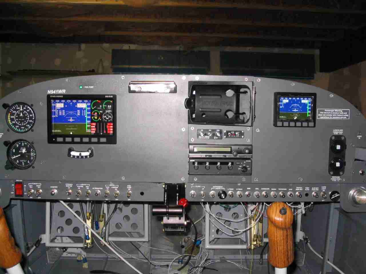
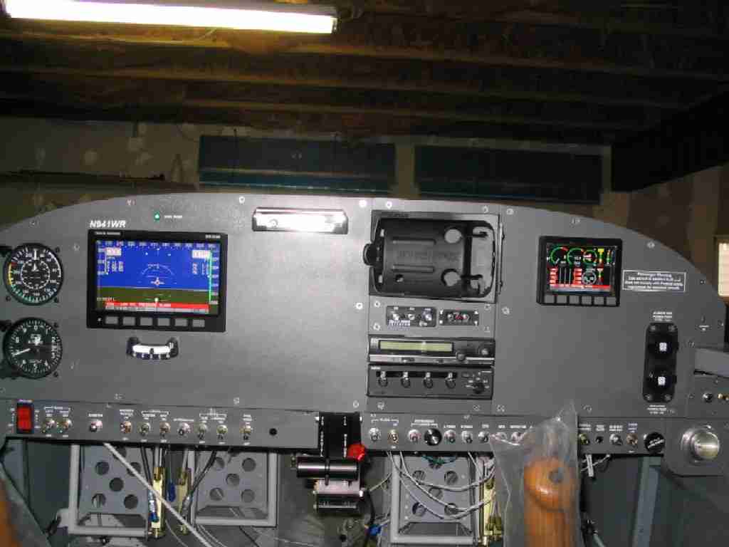
|
 F
The panel labels are done. Or nearly so. I will have to create
a label for carb heat, when I buy and install it. The cabin heat
cable twists the knob so that label is upside down and will have to be
remade. No big deal now that I now how to do it so easily.
Note the two Dynon units are powered up, the post lights and red
electroluminescent strips above the switch
panels work on the dimmer as does the transponder. Next up will be
to wire the radio and test it out. (8/21/06) F
The panel labels are done. Or nearly so. I will have to create
a label for carb heat, when I buy and install it. The cabin heat
cable twists the knob so that label is upside down and will have to be
remade. No big deal now that I now how to do it so easily.
Note the two Dynon units are powered up, the post lights and red
electroluminescent strips above the switch
panels work on the dimmer as does the transponder. Next up will be
to wire the radio and test it out. (8/21/06) |
| |
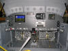
|
  E
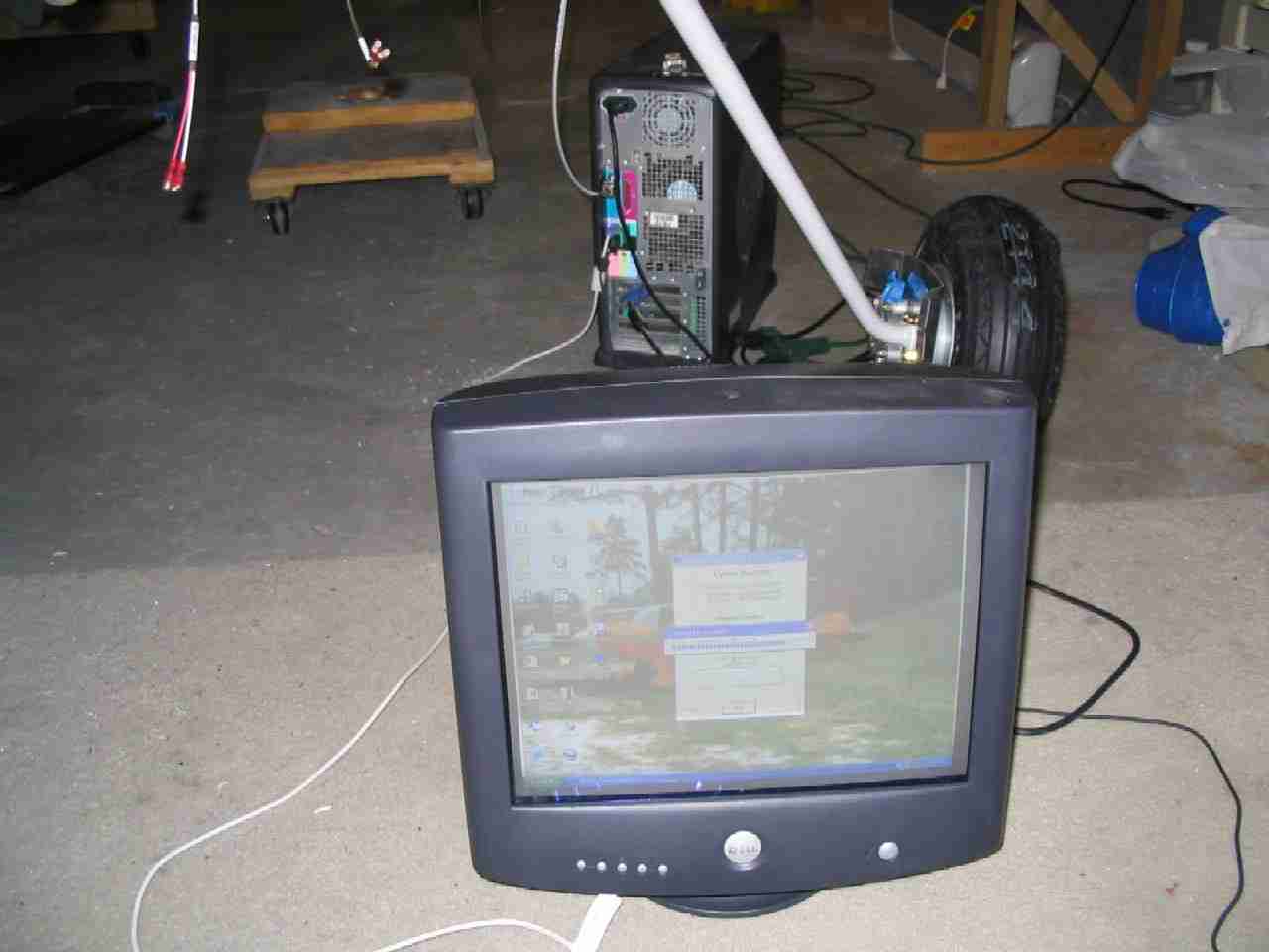
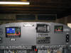
Dynon released the software version for their products earlier this month
and today felt like a good time to perform the upgrade. Not having a
laptop I hauled my desktop down to the basement and connected it, after
down loading the the new software version. Once upgraded, the two Dynons started talking to each other like childhood friends. It
doesn't get any better than that. (9/7/06) E
Dynon released the software version for their products earlier this month
and today felt like a good time to perform the upgrade. Not having a
laptop I hauled my desktop down to the basement and connected it, after
down loading the the new software version. Once upgraded, the two Dynons started talking to each other like childhood friends. It
doesn't get any better than that. (9/7/06) |
| |
|
  F
The best feature is the alarms. When the EMS detects an out of
bounds condition it posts it to both screens and puts a tone in your
headset. All you have to do is hit the acknowledge button on ether
unit and the tone and warning bar goes away, leaving the offending item
flashing. In this case, the oil pressure gauge was flashing as that
was the only alarm I had set at this time. (9/7/06) F
The best feature is the alarms. When the EMS detects an out of
bounds condition it posts it to both screens and puts a tone in your
headset. All you have to do is hit the acknowledge button on ether
unit and the tone and warning bar goes away, leaving the offending item
flashing. In this case, the oil pressure gauge was flashing as that
was the only alarm I had set at this time. (9/7/06) |
| |
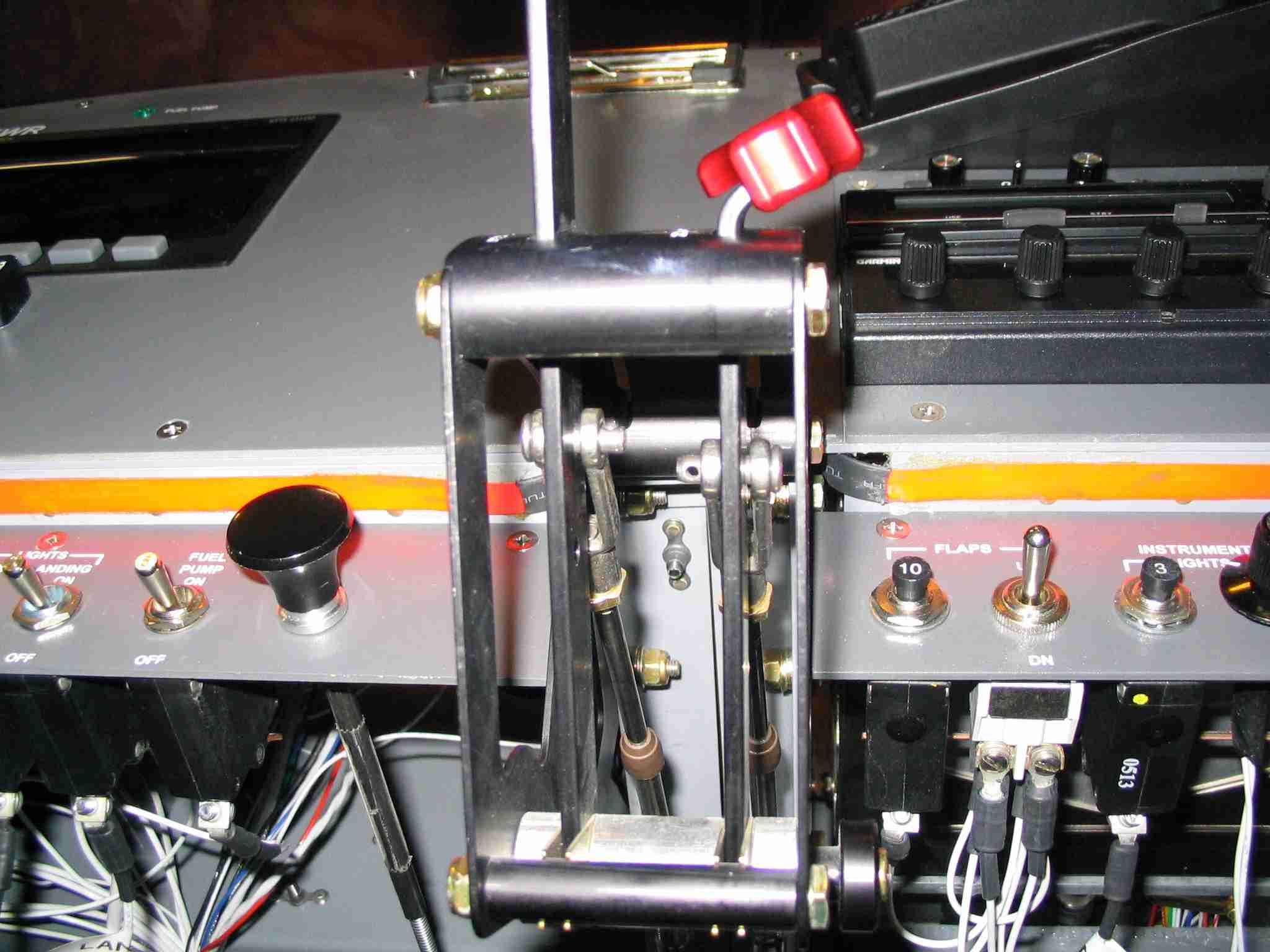
|
 E
Last week I tried to install the throttle and mixture cables and ran into
a few issues. The first was an interference with where I ran my
brake lines. Big DUH moment for me. Second was the clevis ends
I bought from Vans did not have a deep enough throat to allow the throttle
and mixture levels to travel their full distance. A quick call to
Aircraft Spruce had the correct cables here in two days. If you are
using a three lever quadrant, the Aircraft Spruce clevises may be too wide
and you will have to modify the Vans clevises. YMMV. E
Last week I tried to install the throttle and mixture cables and ran into
a few issues. The first was an interference with where I ran my
brake lines. Big DUH moment for me. Second was the clevis ends
I bought from Vans did not have a deep enough throat to allow the throttle
and mixture levels to travel their full distance. A quick call to
Aircraft Spruce had the correct cables here in two days. If you are
using a three lever quadrant, the Aircraft Spruce clevises may be too wide
and you will have to modify the Vans clevises. YMMV.
Which cable lengths to order had me worried until I noticed Vans had
a "stock" 45.5" cable in the catalog which was one inch shorter than I had
measured. My thinking was that if ordered these and they didn't work
out I could always return them and order the longer cables. So far
they look like they are the correct length. (They worked out great
and didn't have to be sent back.) Next week when the
throttle/mixture bracket returns from the powder coater and I install the
carburetor I will know for sure. (10/7/06) |
| |
|
  F
Installing the throttle and mixture cables was easy enough. The
plans call for a #6 Adel clamp but that allowed the cables to slide back
and forth, which is not a good thing. Moving down to a #5 clamp did
the trick and the cables are in for good. Or so I hope.
(10/8/06) F
Installing the throttle and mixture cables was easy enough. The
plans call for a #6 Adel clamp but that allowed the cables to slide back
and forth, which is not a good thing. Moving down to a #5 clamp did
the trick and the cables are in for good. Or so I hope.
(10/8/06) |
| |
|
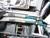
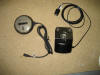 E
In January I found enough cash laying around to order the Garmin 496 GPS.
What a GREAT unit. These two antennas are for the XM radio and
satellites. The satellite antenna unscrews from the suction cup base
and will be Velcroed to the top of the glair shield. (3/1/07) E
In January I found enough cash laying around to order the Garmin 496 GPS.
What a GREAT unit. These two antennas are for the XM radio and
satellites. The satellite antenna unscrews from the suction cup base
and will be Velcroed to the top of the glair shield. (3/1/07) |
| |
|
 F
The GPS is wired in to ship's power and to the Dynon D100. The
heading bug on the Dynon is now driven by the CDI from the Garmin 496.
Very cool! The only thing left to do is to install the wires for the
Dynon capacitance fuel level sensors and then I can clean up the wire
bundles. That and glue the Velcro to the top of the glair shield. (3/6/07) F
The GPS is wired in to ship's power and to the Dynon D100. The
heading bug on the Dynon is now driven by the CDI from the Garmin 496.
Very cool! The only thing left to do is to install the wires for the
Dynon capacitance fuel level sensors and then I can clean up the wire
bundles. That and glue the Velcro to the top of the glair shield. (3/6/07) |
| |
|
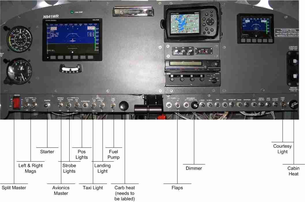
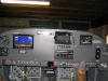
 E
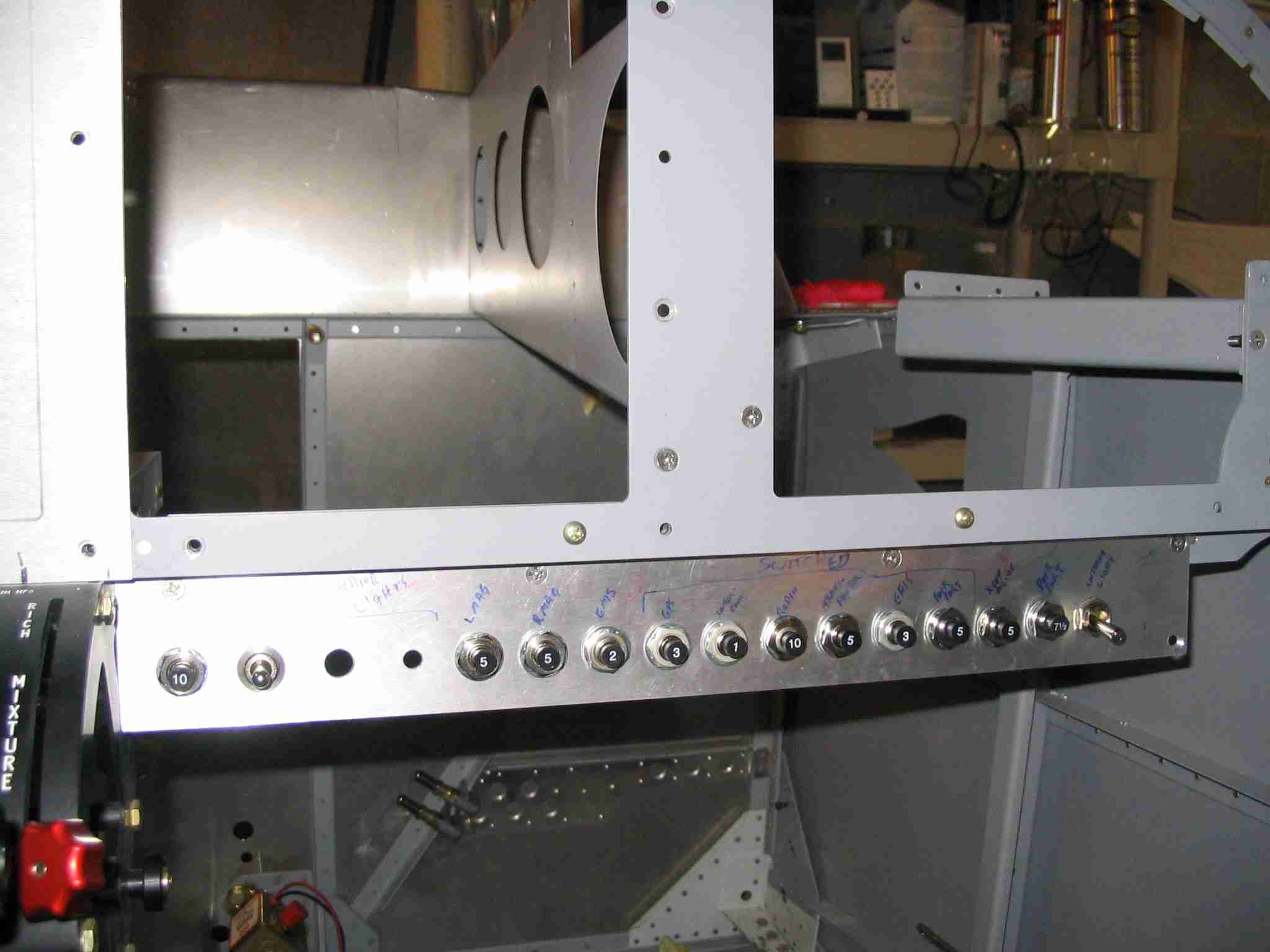
Here is the panel with call outs for the switches. Laying out the
panel is a very personal thing. You may agree or disagree with the
layout, either way, I feel this flows well and puts the switches close at
hand. (3/15/07) E
Here is the panel with call outs for the switches. Laying out the
panel is a very personal thing. You may agree or disagree with the
layout, either way, I feel this flows well and puts the switches close at
hand. (3/15/07) |
| |
|
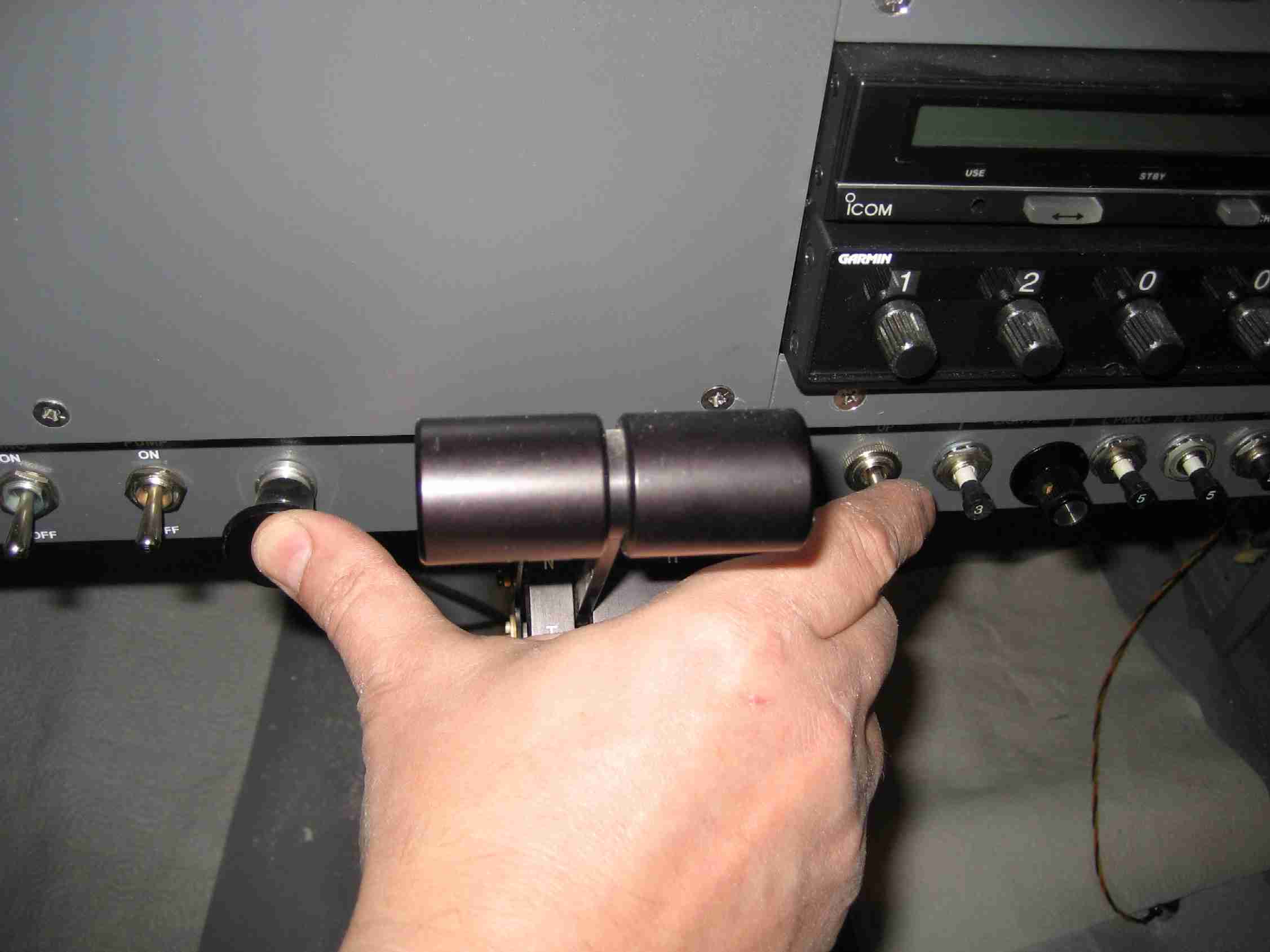
 F
One of my panel design criteria was to position the carb heat and flap
switch so that I could push full forward on the throttle and mixture while
pushing in the carb heat and toggling the flaps up. (3/15/07) F
One of my panel design criteria was to position the carb heat and flap
switch so that I could push full forward on the throttle and mixture while
pushing in the carb heat and toggling the flaps up. (3/15/07) |
| |
|
In a BIG DUH moment I tried to check my Dynon
EMS D-10 to make sure all was ready for their next big software upgrade.
I found I could not communicate with the unit even with my new lap top and
a different USB to Serial cable. Dynon suggested I check my wiring
harness as the unit had already been returned to them once because of a
similar problem. When I got home I checked all the pin-outs on the
DB-9 connector. Sure enough, I had the ground in the wrong hole.
Once that was corrected all worked fine.
 E
The other big thing was that I removed the EFIS D100 and returned it to
Dynon. They offer a screen upgrade to make increase the brightness
of the screen. Although I don't know if I will need this upgrade or
not, the price was reasonable and I won't have to worry about its
availability in the future. Also, I won't have to ground the
airplane if I want it done some time in the future. (4/6/07) E
The other big thing was that I removed the EFIS D100 and returned it to
Dynon. They offer a screen upgrade to make increase the brightness
of the screen. Although I don't know if I will need this upgrade or
not, the price was reasonable and I won't have to worry about its
availability in the future. Also, I won't have to ground the
airplane if I want it done some time in the future. (4/6/07) |
| |
|
 F
After you have installed all the instruments there is still some very
important work to do in detailing the glair shield. First and
foremost is putting something on the edge of the glair shield to protect
your forehead in the event of an unfortunate mishap. The
Self-Gripping Vinyl Edge Trim with Metal Core pictured here is part number
8451A22 available from www.mcmaster.com
is a very nice and hopefully safe trim piece. It is priced by the
foot and is easy enough to install. F
After you have installed all the instruments there is still some very
important work to do in detailing the glair shield. First and
foremost is putting something on the edge of the glair shield to protect
your forehead in the event of an unfortunate mishap. The
Self-Gripping Vinyl Edge Trim with Metal Core pictured here is part number
8451A22 available from www.mcmaster.com
is a very nice and hopefully safe trim piece. It is priced by the
foot and is easy enough to install.
Covering the top of the glair shield is a
personal choice. Here I elected to use the loop portion of Velcro.
I found a source where I could by it in bulk, unfortunately I a minimum
purchase of 15 yards. The stuff is black and doesn't feel like
Velcro, more like felt. It is glued to my glair shield with 3M 77
and looks great. The GPS and XM antennas are simply Velcroed in
place. I have a lot left over and if you are looking for some, let
me know and I'll send you all you need for $25. (4/23/08) |
| |
|
   E
Dynon HS34/AP74 Retention Bracket. Here are three pictures of the
retention bracket I made for the Dynon autopilot head. I did not
like the way the Dynon bracket required three rivets to hold it in place
so I designed something a little different. E
Dynon HS34/AP74 Retention Bracket. Here are three pictures of the
retention bracket I made for the Dynon autopilot head. I did not
like the way the Dynon bracket required three rivets to hold it in place
so I designed something a little different.
The platenut is for a 6-32 screw and I have been told that the location of
the retention screw on the AP76 is different than the AP74/HS34. Just keep
this in mind, should you fabricate one of these brackets.
Note: The AP74 pictured above was a dummy unit provided for test fitting
purposes only. The production unit will have side plates and will be
available labeled for either vertical or horizontal mounting.
(Pictures and comments released with permission from Dynon. If you
have any questions regarding the Dynon autopilot, contact
Dynon.)
(6/10/08) |
| |
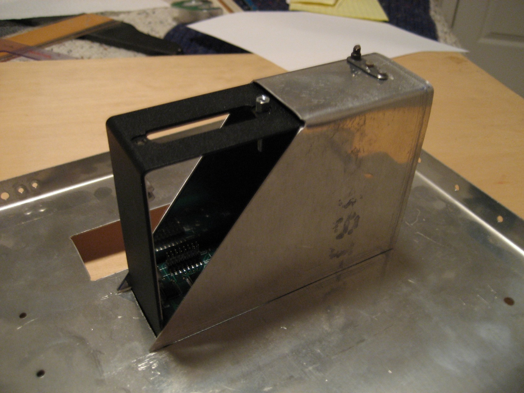
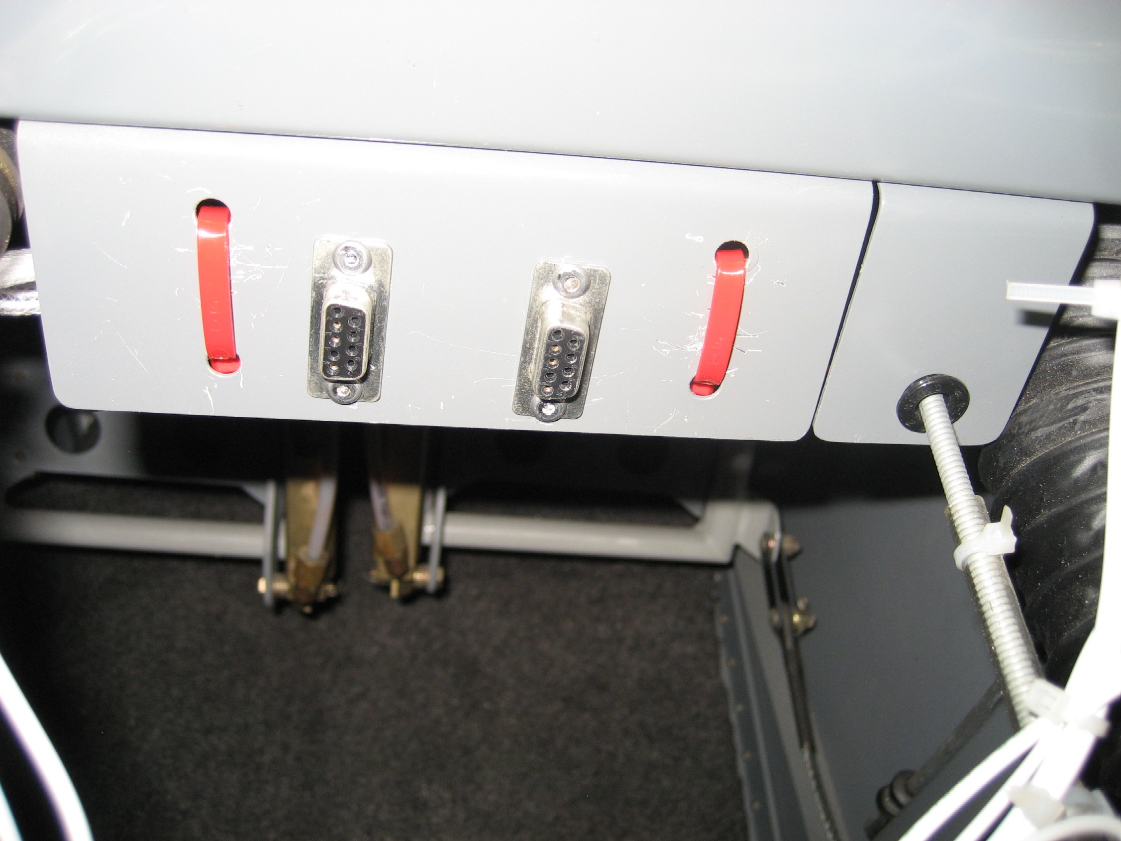
|
 F
When I built my plane, I thought I would only update the Dynon's once or
twice a year. Because of this, I riveted on a piece of the standard
throttle bracket to the sub-panel, drilled some holes in it, and zip-tied
the serial connections to the back side. F
When I built my plane, I thought I would only update the Dynon's once or
twice a year. Because of this, I riveted on a piece of the standard
throttle bracket to the sub-panel, drilled some holes in it, and zip-tied
the serial connections to the back side.
When Dynon asked me to join their beta
team, I found I was updating the software weekly, if not more often.
Because of these frequent updates, it became obvious that I should have
cut the holes in the bracket for the DB9 connectors prior to installing
it. Needless to say, it was a pain to drill and file those holes to
size while sitting in the plane. After this picture was taken, the
DB9 connectors were labeled, EFIS D100 on the left and EMS D10 on the
right. If you are currently building, take
updating your software into account. If I were building today, I
would carve out a square hole in the back of my AirGizmo, make a bracket,
and mount the DB9 plugs back there.
(11/4/08) |